UPDATED 12JUNE2019
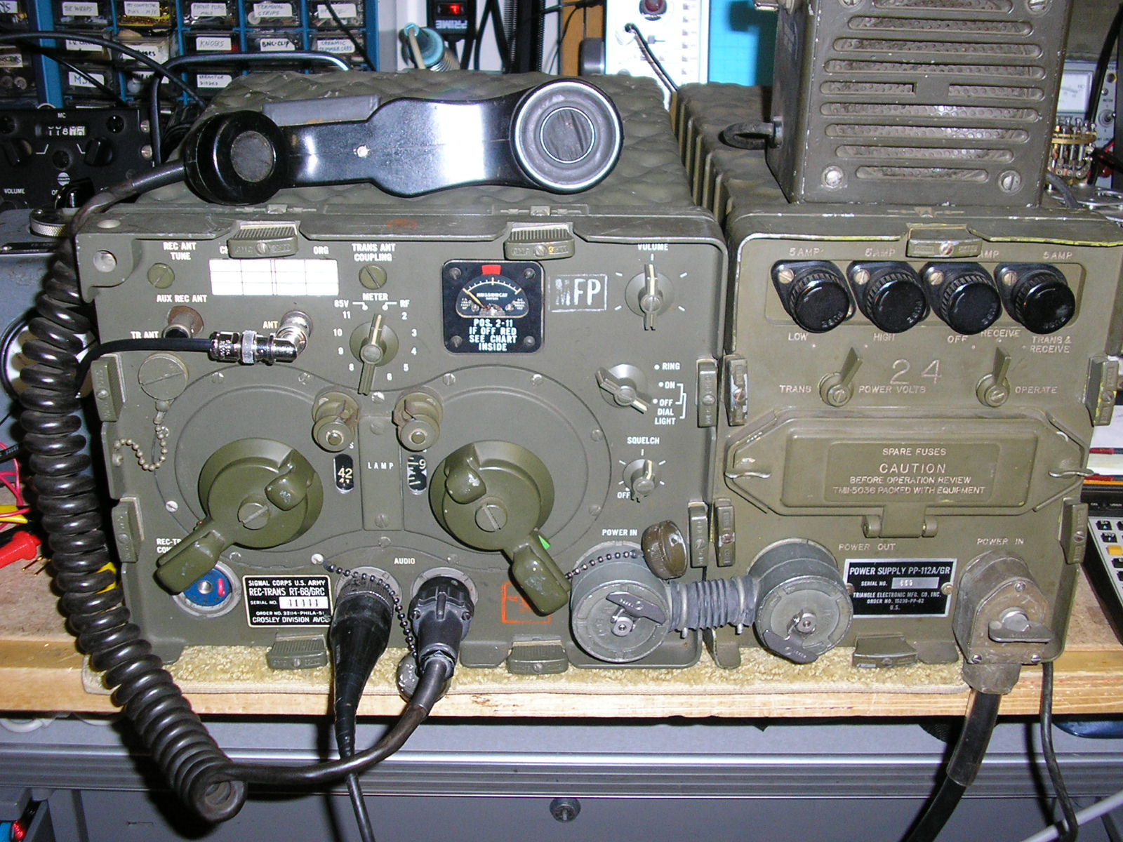
Some fun with an RT-68 VHF FM Transceiver set up with its PP-112/GR matching power supply: The basic VRC-10 pair… I don’t have a shock mount just yet.
Or a Jeep…..
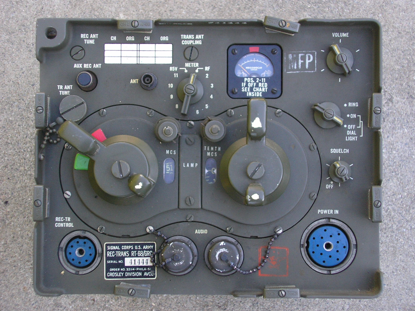
GRC-8 / RT-68 Transceiver N6CC
Documentation:
Refer to Tech Manuals TM11-289, (19 March 1951) and TM11-289/TO16-35RT66-5 (3 December 1953) among others.
The AN/VRC-10 FM radio system and many related ones are based upon the RT-68 transmitter receiver shown here. These radios were designed by the U.S in the late 1940’s and saw service late in Korea and many other theaters in the 1950’s and 1960’s. This one has a 1951 Contract date. They were phased out in the mid – 1960’s by the AN/VRC-12/RT-524 systems. Reference (20). As part of a versatile system, the “VRC-10” provided FM voice communications with a power output of up to 15 watts, 2 watts on low power. Planning range between similar units was approximately 15 miles for stationary vehicle operation, 10 miles between vehicles in motion.
This “Old Family” radio runs wide band FM with an effective Carrier-Operated squelch. The receiver is 85 KC wide at the 6 db down points; hence the 100 KC channel spacing. The transmitter deviation is probably +/- 15 KC. The receiver sounds nice and clear with punchy, room filling audio when listening to modern FM transmitters operating in the Land Mobile bands. If those signals are pretty weak (and can’t fill the pass band anyway), it sounds pretty noisy as expected. Working with my VRC-7 / RT-70, PRC-6, PRC-10 and PRC-25 it sounds great – both ways.
John Rambo even used one (Rambo 27 I think) in the headquarters of the evil Lieutenant Colonel Padovsky in the POW camp. Rambo switched freq’s on the RT-68 and – even with no power supply connected or even present – ahem – informed the treacherous Murdock that “I’m coming to get YOU”. Murdock somehow heard him. Impressive!
This radio operates on 170 discrete channels in the 38 – 53.9 MC range, designated for Infantry units. In those days there were 3 discrete frequency bands for ground forces; combined arms communications interoperability came later as technology improved. Armor operated in the 20 – 27.9 MC range (AN/VRC-8) and Artillery was in the 27 – 38.9 MC range (AN/VRC-9) with their RT-66 and RT-67 respectively. The middle “artillery” range overlapped with the other two by 9 100 kc spaced channels to permit communications between combat arms – except the Infantry could not communicate directly with Armor. Great. But this was driven by the technology available at the time and was a big improvement over the pioneering WWII tactical FM sets.
These radios were part of an overall U.S. Army communications system and were interoperable with the man-pack PRC-8, PRC-9 and PRC-10 respectively. It was also backwardly interoperable with the WWII SCR-300 / BC-1000 Walkie Talkies. The AN/VRC-10 was further interoperable with the PRC-6 Infantry portable on the high end of the VHF band where short antennas were more efficient (and more importantly, harder to see). It could also communicate with tactical air assets using the AN/ARC-44 sets in those aircraft.
This series also permitted a field telephone interface so a field telephone operator could communicate by a remotely located radio at a favorable terrain location. Since radios are frequent artillery magnets, this was a good idea. See the Technical Manual, Reference (19) for further details.
I obtained mine at a Ham swap meet “condition unknown” but it looked to be in NOS condition – a good find for 20 bucks. Upon opening it up at home, I found that it had been dropped hard sometime in its first 50 years of life, rendering it NFG (Not Functioning Good). Further investigation revealed a slightly bent chassis frame but the main tuning gang capacitor assembly in the RF chassis had suffered a broken ceramic rotor shaft – an unrepairable show stopper. A REALLY bad show stopper. No rotation, shorted plates, unknown short circuit damage etc. These radios are very rugged – they are the radio equivalent of the Main Battle Tank. However, F = MA. Every time.
After obtaining the RT-68, I obtained a 24 volt PP-112A/GR power supply at another swap meet and an interconnect CX-1211/U “dogbone” cable to power the radio. These two units along with the shock mount, control box, antennas and audio devices was known as the AN/VRC-10. With a combined weight of 73 pounds just for the RT and Power Supply, this is a true Boat Anchor – or install one in your Prius to keep from getting stuck in the snow.
Apparently the Army operator, organizational and depot level repair guys thought my RT-68 was beyond repair, so it was probably “excessed” as Beyond Economical Repair or relegated to “storage” for repair if they ever got really desperate for a replacement radio. Hence its NOS condition – it was clearly never installed or used anywhere. The radio is practically built around this variable capacitor and the radio must be completely disassembled to get to the capacitor – and then about 20 inaccessible solder connections had to be opened to be able to remove the part. That after you first removed a bunch of unrelated mechanical gears, couplings, shields and other access interferences. So that’s the job I inherited.

RT-68 6-Section main tuning capacitor Ass’y
Above is the RF chassis after removal from the front panel and main chassis – then separated from the IF chassis. The 6 gang main tuning capacitor is shown here, missing the gear driving the broken shaft of C1.

RT-68 main tuning capacitor – broken ceramic rotor shaft
Above shows the broken (white) ceramic shaft that the rotor plates are connected to. When the shaft broke, all the ball bearings supporting the gear shaft evaporated to parts unknown, Can’t get the ceramic out, can’t insert new ball bearings, can’t imagine an adhesive that would work in this instance. Beautifully machined brass and stainless steel parts, especially the antenna trimmer cam system seen here. Much more eye-appeal than varactor diodes!
Fair Radio came through with a parts chassis, sans tubes, crystals, meter, cabinet etc – but it contained a usable C1 capacitor assembly. Lots of troubleshooting time, circuit study, test gear setup, then surgery. Two long days later, the capacitor had been mechanically swapped out. Two more long days of alignment fun and old Serial Number 41444 was back up to specs. Fortunately the PP-112A/GR power supply fired right up with the 3 different vibrators humming right along. Now I have to find an MT-299 shock mount and a few other bits for the complete VRC-10 system.
AN/VRC-10 FM Radio Set N6CC
Until I find a reasonable MT-299 mount, I decided to build a field expedient “mount” to keep the radio and power supply mechanically connected. This is primarily to protect the Dog Bone interconnect cable assembly while moving the chassis around.
I took a piece of 3/4 inch plywood and mounted five pieces of 3/4×3/4 inch, 1/8 inch thick angle stock to the plywood base. The chassis skids of the RT and Power Supply fit tightly between them and they take the chassis weight. I took some 1/8 inch diameter steel rod and used it to slide through the angle rails and the steel roll-pins in the chassis skids. These 2 long pins serve to capture the 2 chassis to the “mount” but don’t bear any weight. I threaded the ends of the rods and tapped holes in the end-plate as shown in the photos. This keeps the steel pins in place. Works great. Next step is to install four Barry Mount vibration isolators under the plywood.

Homebrew VRC-10 Radio Set Mount N6CC
Above: The plywood base with four aluminum angle rails and end-plate to accept the RT-68 (foreground) and power supply skids.

Steel rod threaded into mount rails
Above: Detail on threaded steel pins as they attach to the mount.

RT-68 mounting assembly – Steel Roll Pins
Note the Roll-Pin in the Power Supply chassis mount skid. These were originally used in the MT-299 as clamp anchors. These Roll-Pins are steel, slightly bigger than 1/8 inches I.D. Perfect fit for the steel rods to attach the chassis to the mount. I use the same technique in my VRC-7/TR-70 in the Bronco. (Can’t afford one of those shock mounts either!)

RT-68 sitting on mount
Detail. Note looped end of steel pin protruding from angle aluminum. Just unscrew and pull out to remove chassis from mount.

MVCC Battalion Comm Center Tent
Here’s the VRC-10 on its first field deployment: The Battalion Comm Center at Camp Delta, Military Vehicle Collectors of California rally and camp out. The VRC-10 covered the VHF tactical circuit feeding a “jungle antenna” wire ground plane suspended from the trees. Very effective combination!
In typical vehicle service the antenna system would include the AB-15 base and one each MS-117 and AB-24 mast sections to approximate a quarter wave whip.

VRC-10 in the Tactical VHF Position
Here flanked by the PRC-10 and PRC-25 FM radios.
“White Rook this is Raven. BEADWINDOW 7 – you are on the wrong circuit! Out”

VRC-10 Radio Wire Integration
Above: Meanwhile, down in the Commo Bunker: The VRC-10 remotely controlled via the GRA-6 Radio Wire Integration system. The transmit/receive remote control can be located up to 2 miles away when connected by WD-1A/TT infantry field telephone wire. This system works great.
For more information about this set, the VRC-7 and the PRC-47 controlled by field telephone systems, take a look here: AN/GRA-6 Radio wire integration
Nice write up and pictures!
Glen
N6PQP
Thanks Glen – A “fun” project for sure. An amazing design and packaging design for that era….
73, Tim
NECESITO LOS PLANOS DEL RT-68/GRC Y DE LA FUENTE DE 24 VOLTIOS PP 112 A /GR ME FALTA EL CABLE DE INTERCONEXION CX-1211/ U “DUGBONE”.OSEA CONSEGUI UN RT-68 /GRC Y ME FALTA LA FUENTE DE PODER ,EL CABLE DE INTERCONEXION.SOY DE REPUBLICA ARGENTINA.SALUDOS ATENTOS A TODOS LOS AMANTES DE LOS EQUIPOS MILITARES.
Hola Marcelo – Y buena suerte con su RT-68. Possible E Bay para los equipos? Estan alli a tiempo, yo comprendo….
73!
Tim
I’ ve recently picked up one of these rt-68/grc with an order number of ph-51 and a very low serial number of 8747.
I was wondering how to find the date of manufacture or order date.
I also picked up a p-112/gr with no order number and a low serial number of 7252.
Any info on how to date these items would be greatly appreciated.
Hi Dave – I am pretty sure (certain) that PH-51 is the contract date (1951) and pretty sure that Ph indicates it came out of the Signal Corps contracts office in Philadelphia PA. I believe that Contract Date and Order date is the same thing…
As to manufacture date, that is more obscure, obviously some time after 1951. I don’t know of a cross reference of that type of information by serial number. Some components like especially vacuum tubes have date codes on them, but again, that is the date of the tube manufacture and those could be older stock.
Have fun with it!
Tim
Hi, great job! I also have an an/vrc-18 that im trying to get up and running, but im afraid im over my head with it. Do you offer your services for hire, or recomend somone? Im in walnut creek ca,
Thanks
Hi Mike – thanks for the note…Unfortunately I am not in a position to work on projects like yours. I have a pretty “infinite” task list myself and my wife has other ideas for my time anyway!!
The good news is that if you have all the parts and they are all connected “by the book” chances are good that it will work well enough for some simple troubleshooting if needed. They are well made using quality parts… The power supply vibrators are the most likely parts to be a problem – and they can usually be fixed by cleaning the internal contacts. Lots of info on Google regarding those..
I don’t know anyone who does this sort of work – it is a common problem with this old gear. Troubleshooting, repairs and parts location is extremely time consuming and rarely worth the “cost” of doing the work. Same with modern electronics – unfortunately we are in a throw-away economy…
Sorry I can’t be of further assistance…could be a tough problem but you might get lucky…
Tim
Hi folks ! This is just to share my experience; by 1987 I got an RT68GRC and PP112. It was working. I changed some parts of the Power Supply, and transistorized all the receiving section with MPF102 (FET transistors that fit well instead of vacum tubes, thanks to a friend -long gone- who tought me how to do it, as tip: two fet for one valve works like a charm). Anyways, it took me a LOT of time to do it, but the whole thing is SO WELL documented that it was possible, I did it. Feeding so good quality transformers on the PP112 with 50Hz AC posed no problem at all. Also added 12 volts (7812) line. Tx section remained intact. I operated the RT until 1991 (got married then). 32 years on, today I powered my RT (no flames yet jaja). Saddly I through away all my notes regarding the modifications I did, though I still have the TM11-289 maintenance manual (it’s on the web anyways). Hope to put this loved peace of electronic and mechanical art back on air some weeks ahead. I look at it and can’t stop loving it (hey I’m a regular guy, love my son and my wife,sure thing) but the radio is in my heart since I was very young (15 when I got my license). Thanks for the beautiful photos. Keep in touch.
’73
Anibal
Hi off the top of your head do you the the dimension of the MT-297 radio mount H,W,L thanks for any help ka9dzr Dennis
Hi Dennis – I don’t know (I don’t have one). You might try the Manual (TM11-284). I’m sure it’s in there….
Tim
Posting this here because of the “Mount” question. There were so many variants of this system, depending on the radios they were populated with. I used to have ALL the associated Field Manuals (Tech Orders for us AF pukes) but sadly hurricane Sandy took care of that. BUT, depending on the mount, the radios and amplifiers in it, and what type of Local Control equipment you had, you could make the radios operate as a REPEATER. In the above picture is the Local control C-434. In the above use, it just connects to the Remote control C-433. With the correct mount, the C-434 PLUGS INTO the mount, simplifying its connection to the radio/s. Take it out, and replace it with a C-435, and with the correct switch settings it will RETRANSMIT whatever is received on the other radio. One mount would have an auxiliary receiver, an RT-68 & it’s power supply, an AM-65 audio amplifier and an RT-70 transceiver. OR 2 RT-68s. You could have one hell of an HQ setup, depending on the mount and what radios you had for what bands you wanted.
I’m not sure of the nomenclature-I think the systems were GRC-3 through GRC-8 as well as VRC-10 through 18, but I’m not 100% sure anymore. It’s definitely worth looking up though. It’s a damn shame I didn’t find you guys when I still had all this stuff!
Hi,
Great story and nice pics!
I do own a M38A1 and recently bought a RT-68. I was wondering if that will work with an antenna with MS-116/MS-117/MS-118?
I do also have the correct mast-base though!
Remco
Hi! I believe the correct antenna section for the RT-68 (in any number of system variants) is one each AB-22/GR and AB-24/GR. The base is the AB-15/GR. The set will work with the MS type antenna elements however.
Take a look here for the complete manuals for these radios and systems: http://radionerds.com/index.php/Main_Page
Have radio parts just like you pictured if anyone needs a set contact me at email will send price pictures. John
Hi John – Thanks for the offer! Anyone ??
Thanks for visiting…
Tim
Dear Sir,
Thank you for the above write up. I just purchased the same radio (RT 68) and power supply for $20 as well. Along with a box of fuses and tubes and I think a power inverter. I do not have the power cords to see if the unit works.
Do have any leads as where I maybe able
To purchase the power cords? I can send a picture if that would help.
Thank you for your time.
Sincerely,
Dan Maloney
Hi Dan – Congrats on your new radio! I don’t happen to have any spare cords – those being the radio-PS “dogbone” and cord from the PS to the battery. You might check Fair Radio Sales, they often have such things. Or also EBay or course.
You can find the radio manual here – it will have the specific cord numbers you will need to locate. https://www.radionerds.com/index.php/AN~GRC-3
Thanks for stopping by! Tim
Need to know the correct number and type for the power in connector for the GRC-8 radio. And if anyone knows how to get a battery supply cable as I have a hand crank G-8A generator with this same connection for power out and need to power a GRC-8 radio or ideally be able to convert it to charge regular things like cell phones in a SHTF situation.
Hi Jared. The RT is normally powered from the DC power supply via the power connector on the “dogbone” connected between the 2 units. I don’t know the connector or cable number for the G-8 to RT, those seem to be quite rare, I have never seen one. You might give a call to Fair Radio Sales and see if they can help you. The manual for the G-8 is this one TM 5037 1951 and the manuals for the whole GRC-(*) series can be found on the Radio Nerds website, it may be in there someplace.
The G-8 has an output at 6.3 VDC, 2.3 amps. With an external 5 volt regulator chip and proper connectors it could charge anything at 5 volts.
Tim
I am the owner of a 1952 Army M38 Jeep, of which I have a AB-15/GR Mast Base with antenna for the AN/VRC-8, -9 or -10 ground radio. I am interested in buying a set to include the RT-66/GRC and PP-112/GR. If anyone has a set for sale or know of a possible source it would be appreciated.