
Updated 6/12/2024: Some notes regarding the AN/PRC-47. This radio was designed by Collins and 1423 sets were produced by them (Contract NOm-72362, 15 December 1961). The Department of the Navy also contracted with Bendix to produce additional sets in a competitive bid.
All the Collins sets were identified by the Federal Supply Code for Manufacturers (FSCM) on the data plate as 13499. Those built by Bendix have the FSCM of 06845. I have found no obvious differences between them; mine is a Bendix-built set.
The Operators manual is TM 11-5820-509-12 The Depot manual is TM 11-5820-509-35
It seems that the PRC-47 was primarily used by the US Marine Corps in Vietnam but there are many references to its use by the USAF and US Army as well. They were also used by the Navy during Market Time coastal patrol operations as a base operations radio supporting Swift boat comms.
I believe their use was widespread as it is a versatile and reliable radio that is particularly weather resistant unlike the FRC-93 (Collins KWM-2) that also saw widespread use in fixed installations.
The Australian Army also used the PRC-47 in Vietnam. Photos are on the web of the Australian 104th Signals Squadron at Vung Tau operating a PRC-47 in a vehicle on CW. That radio also had the CV-2455 RATT converter installed. Thanks guys – we remember.
I will focus on actual field use in the Navy and later on in use as a transceiver on Ham Radio freqs in the field. My Navy unit used these radios during many training exercises in the 1970’s and early 1980’s. The Marines had begun the transition to the PRC-104 and the Naval Amphibious School at NAB Coronado was “surveying” their PRC-47’s.
They had been using the PRC-47 for many years prior and theirs were pretty worn out. We were authorized to draw excessed Property with the standard “1149 Form” and soon we had a few radios on our books. The unit ET’s (Electronics Techs) got them back in shape after some work and we were in business.
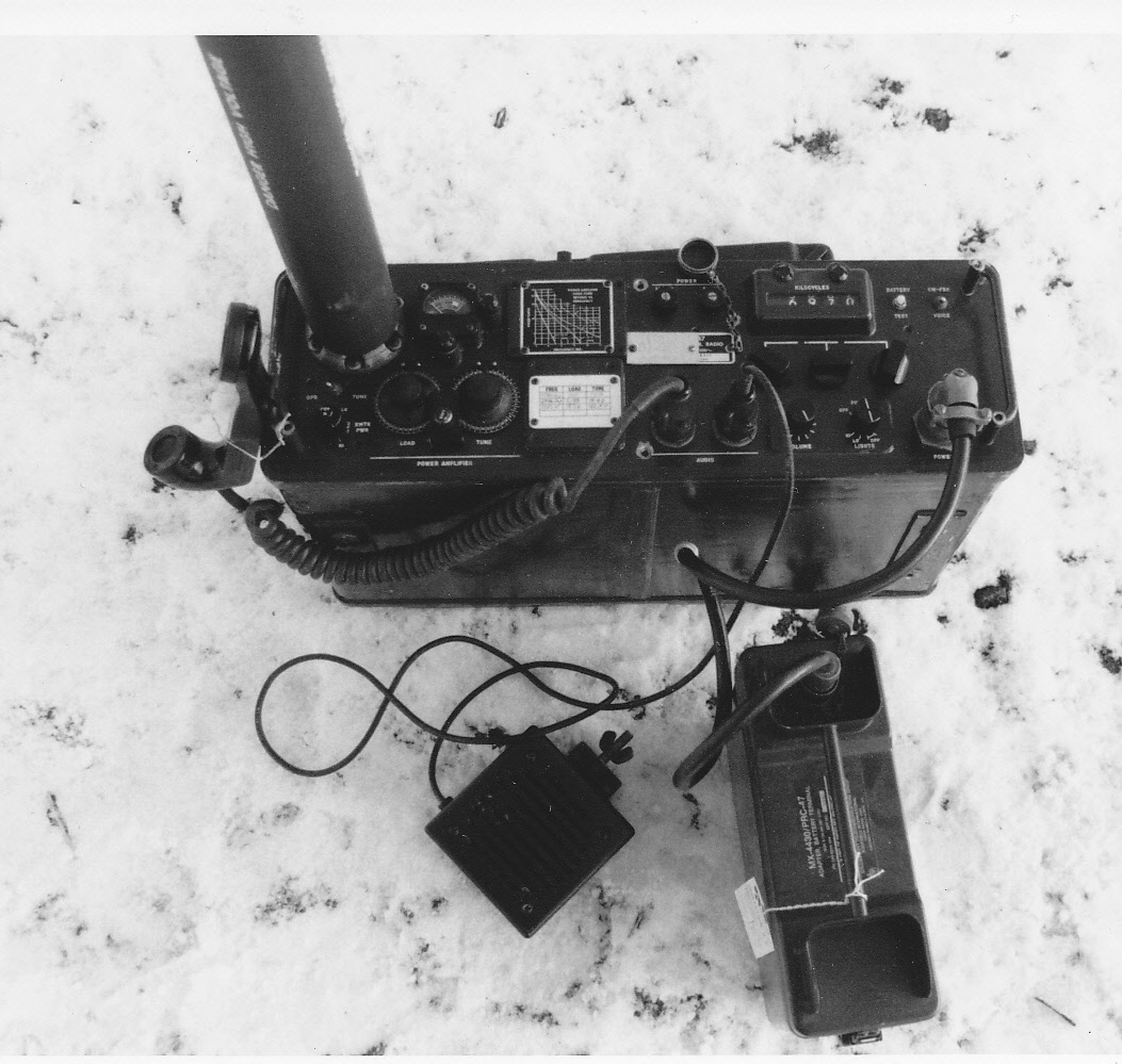
The photo below shows U.S. Navy personnel in a coastwatcher communications training exercise on a Pacific beach around 1982. Upon landing, they made a “Feet Dry” radio check to indicate safe arrival prior to moving inland to a more favorable OP location.
In this case the PRC-47 was being powered by two 12 volt lead acid batteries in series because we apparently had problems with either the silver-zinc batteries or their charger. (Improvise, adapt, overcome).
Authors Photo:

This was a typical training exercise conducted by Mobile Inshore Undersea Warfare Unit 1920 (later renamed as MIUWU 103). Coastwatchers would communicate back to the primary surveillance site with the PRC-47 if they were out of range of the PRC-77 that they were also equipped with.
In this exercise, we were operating within ground wave range. Therefore used the standard whip rather than the low horizontal slant wire or inverted “L” wire antenna (NVIS-capable) which we normally used for longer ranges. The use of wire antennas were entirely dependent upon available cover, concealment and supports at the surveillance site as well as range considerations.
We had assignments of several low frequencies to take advantage of the propagation/time situation as necessary. With military operations it’s nice not to be constrained by Ham-Band frequency limits. We just get assignments from the Navy frequency coordinator. It allows you to think “differently” about establishing comms….
These 2 sailors are a Chief Bosn’ Mate and a Gunners Mate – not Radiomen. They were cross-trained in tactical radio operations among many other skills – and could make things happen.
Below is another shot of our PRC-47 set up on Mt Rose, Nevada during a cold weather training exercise. MIUWU 1920 was working with Charlie Company, 4th Recon Battalion Marines based at the Stead Facility (home of the Reno Air Races) north of Reno. A few days in the snow doing cross country skiing, snowshoeing, cold weather survival, land Nav and of course, Comms.
I note that this radio is tuned to 6970, our assigned 6 Megger freq for this exercise – the same freq we used on the PTF boats back at Great Lakes. It was a commonly assigned Navy HF training freq back then. Notice the lack of ground radials when the photo was taken – hopefully a “teachable moment”. We were on about 20 feet of snow – a long way from “ground” !
When using an unbalanced antenna such as the Whip or single wire antenna, the radio (ANY HF radio) chassis MUST be RF grounded with a suitable ground wire array to keep the chassis at “RF ground”. Not needed with a dipole – its’ “ground” is the “grounded” leg of the dipole itself.
The transmitters’ output impedance matching network requires the ground to function properly when using an unbalanced antenna. In addition to not tuning properly, the chassis will he “hot” with RF power and that will burn you when you touch the handset or chassis (YOU are now part of the antenna matching circuit).
While not lethal, you will probably make this mistake only once…. Consider the thickness of that fat foam antenna base insulator. The chassis can become hot with a similar RF voltage – but no insulator to protect you! Ground it!
I recall that keeping the BB-451 battery insulated from the snow extended its charge life. Not surprising. We were using it to maintain a comms schedule, 170 miles back to our base at Treasure Island CA. Worked great.
Trying to sleep with an icy BB-451 inside your sleeping bag is a treat. They (the sailor and the battery) work better when warm.
Below is a poor photo showing LT “G” in the back of our 2 1/2 ton truck set up as a mobile Command Post during an exercise at Camp Pendelton CA. He had the mid-watch apparently. That’s the PRC-47 back in the shadows with its H-33 handset coil-cord dangling.
He was the OOD and received coastwatcher reports from the deployed team via HF. That and other information was radioed to the exercise umpires aboard ships in the Amphibious Task Force at sea. Great training – but that is another story in itself.
")
Also, that’s a Yaesu FRG-7700 Ricebox HF receiver we would bring along to monitor other HF circuits.This was the Jimmy Carter era and the military – and especially the Reserves, had little funding for anything – sometimes we brought our own gear to get the job done. Improvise, Adapt, Overcome. HOOYAH! Authors Photo:
Moving on to “Civilian” applications. Although PRC-47’s look deceptively like a “turn-key” radio for a Ham to use, I would not consider them to be a “beginners” radio if there is such a thing. Unless of course if you got one that works straight away. There is a lot going on behind that panel…
Ham Radio RATT With the CV-2455 Converter: I captured a NIB CV-2455 converter many years ago from Fair Radio but I don’t have a suitable terminal unit. Long ago I built an interface to run AFSK with an FT-101 with an old AST Advantage NB-SX25 notebook PC running some software I got from a Canadian ham, VE3LNY. Worked great. Looking for a 28 VDC Mite if you have a spare that needs a good home. I can’t run MMTTY on the Laptop – can’t handle it!
But now that I have the PRC-47 going I needed an interface to convert the CV-2455 loop current into TTL levels for the old notebook PC. I designed a circuit using opto-isolators and level converters to interface the 20 ma loop current to the serial port and vice-versa and it works great as well. Trouble is, I can only work RATT stations running 850 cps shift, Space high, USB AFSK, 60 WPM, the US Military standard MIL-STD-188-110B. But that’s the whole point!
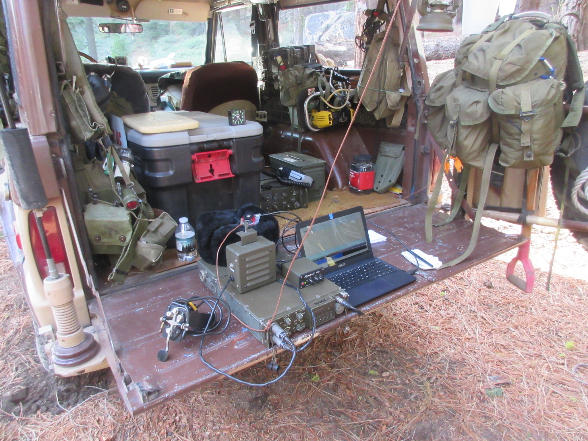
Below is a photo of the PRC-47 with the RATT system mounted in the back of the Bronco. It’s not permanently mounted on shock mounts so I can take it out and use dismounted when necessary. The small box with the blue front panel is the interface between the CV2455 and the ancient DOS notebook computer. A really old computer but it runs the system perfectly – and is therefore not obsolete!
I had been powering it with a second deep cycle 12V battery in series with the vehicle battery for 24 volts. I had it switchable to charge them both in parallel and then into series for operation.
Later I installed a 12V-24V DC-DC converter rated at 480 watts as a trial. It does the job running the radio on High power, the switch provides fused 12 VDC for the input. So far initial tests find it to be RFI quiet. Still checking various freqs/bands.

Works great.

However, turns out I am not alone in running the military standards. The RATT Clatternet formerly running in the Pac Northwest was running such a net with their own Mil gear, including GRC-106’s, PRC-47’s with Mite terminals etc.
In the 1990’s I worked them many times on their 10.137 MC freq and then on 40 meters as well. That included W6GER, W7LFK, K6FIB and N7EPI. Worked a number other guys in San Diego on that net too. However, they QSY’d down to 80 meters as that supported their local (NVIS) situation better than 30 or 40 meters for that time of day. I had listened for them a few times on 80 meters but no joy.
—————————
FLASH 8/9/14 There was renewed interest expressed at the May 2014 West Coast Military Radio Collectors Group gathering to revive the Clatternet (II).
Since then, we have run a RATT net for close to 2 years with several other people getting “re-interested”. Look for us on 3587, 7087 or 10137 Kc on Sunday Evenings around 0330Z, most likely on 7087 (at 0100Z on 3587 in the winter) for now. Plus/Minus in 1 Kc increments as QRM dictates. 850 cps shift, 45 baud, Mark Low, (USB AFSK. fldigi/MMTTY if you need to.) Hopefully it will move to entirely mechanical TTY terminal machines as time goes on. But at least military radio equipment and emission type for now.
FLASH: 3/28/20: CLATTERNET III is back in casual but sporadic operation on the West Coast after a years’ stand down. H-Hour is sometimes 0100Z Sundays depending upon propagation and daylight savings time follies. Informal skeds are often arranged via EMail first.
In late 2022 we are now operating at 1730Z Saturdays on 7087 kc (window frequency), 850 cps shift, Space high, 45 baud. I’m still running the PRC-47 with the CV-2455/PRC-47 RATT AFSK converter but sometimes with a Signalink interface. Mark is on 7088.575 kc, Space is on 7089.425 kc to accommodate the PRC-47 or other SSB-based AFSK system.
Our East Coast MRCA military radio op “cousins” are also running RATT ops with these setup specs as well.
A recent experiment is to run the stock USB PRC-47 on AFSK RATT using a Signalink USB interface with a laptop PC “glass terminal”. Software is FLDIGI. Wide or narrow shift and M/S polarity set by the software.
All it took was to fabricate a cable with an RJ-45 on one end, a U-77 on the other. I also squeezed a DC blocking capacitor inside the U-77 to protect the Signalink from the DC mic bias used by the PRC-47 for the H-33 carbon mic handset. The blocking cap could have also been installed on the jumper header Mic connection inside the Signalink box. Works great, however:
One significant issue with my PRC-47 is the 400 cps HV power supply switching noise is audible in the signal. This is also true while running RATT using AFSK to generate the MK/SP tones. The output is not clean and I need to address that. Sorry for any QRM up until now.
[Note to self: When powered by DC, it is probably the 400 cps square wave in the PA and other filament circuits coupling into the signal. That may be unfixable.]
[OT] I can also operate on the Clatternet RATT circuit using the PRC-174 as shown below:
The Tailgate TOC:
The above setup is a little simpler to use than the PRC-47 for dismounted or portable Ops. Here using the Signalink USB interface with a Win10 Laptop running FLDIGI software on the Clatternet from a remote campsite. Inverted L Antenna up in the big trees. Tailgate Teletype.
This setup also gets me into the Internet EMail system via a WINLINK HF Gateway node if necessary. Very handy from remote locations where nothing else works.
The PRC-47 drives the MP-57/MS whip or a dipole/wire when stationary. It works well on SSB but I have not connected with anyone running Mil standards via the whip yet. I had it out to the Military Vehicle Collectors of California (MVCC) Camp Delta in September as well but there was no one up on RATT then. Next year!
It’s a good system. The PRC-47 is stable and the CV-2455 has very sharp filters so I can read signals barely above the noise. It drives the transmitter fully, of course with the USB (standard) filter module installed. The Convertor utilizes AFSK to drive the transmitter mic circuits. I carry another Amplifier-Modulator module so I can work LSB voice with the PRC-47 as necessary.
The CV-2455 cooling blower is serious! Runs TX at 100 Watts with barely a detectable change in the output air temperature. Great design – but it’s LOUD! Sounds like a Shop vacuum.

Above: Three PRC-47’s set up and operating at our “Battalion Communications Center” at a Military Vehicle Collectors of California rally at Camp Delta. We had one on 40 CW another on 40 USB and the third on 30 meters CW. (Plus a 4th one in the Bronco set up for RATT.) Phased array anyone? You’d just have to be real fast at connecting the batteries to the proper set at the proper time to establish the directional radiation field. This setup drew a curious crowd….

More PRC-47 testing. The battery jumper cables run off to the water faucet “ground system”. OK, which one sounds better – this is Radio # 1…..Stand by…..

Above: A PRC-47 and GRC-9 covered the HF comms requirements on this mountaintop near Lake Tahoe CA. A very quiet radio location a LONG way from any RF interference sources.
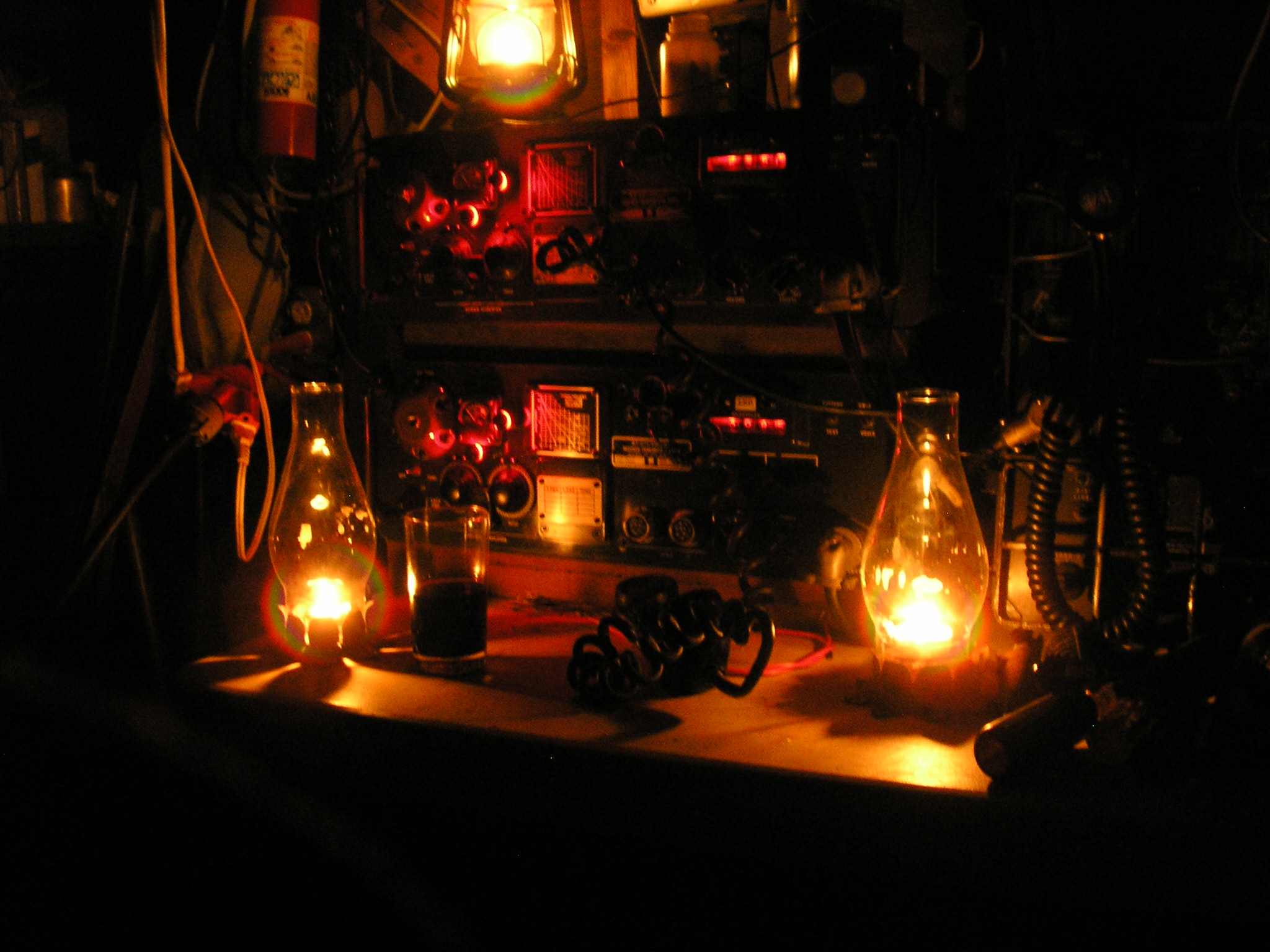
Above: Night Ops: PRC-47’s standing by in the Commo Bunker. The upper radio is for USB, the lower radio is for LSB – just move the antenna lead-in to the radio of choice.
The PRC-47 can also be operated remotely with the Control Group AN/GRA-6. It is also a field telephone system connected by up to 2 miles of WD-1A/TT commo wire to control the radio.


Above: My camper buddy operating the PRC-47 remotely from his tent. The radio was about 100 meters back into the forest. This system can also power the radio ON and OFF without a need for a local operator at the radio. Very handy!
At the other end of the wire the radio can also be operated under local control:

When deployed “by the book” these are great campsite radios. A low dipole antenna usually works much better than the whip for regional comms inside of a few hundred miles. Here working some ARRL Field Day LSB cross-country contacts from the mountains.
Below is a shot of my buddy, caught in a night FLASH while sending our SITREP traffic. Or was it trying to order a Delivery – Pizza? We were up in some remote campsite and were using his PRC-47 “dismounted”. In this case powered by two 12 volt deep cycle Marine batteries. Ground radials deployed, vertical whip, these radios work great.

Below is another shot of the same site during the day.

Below is a shot of my PRC-47 operating “semi-dismounted” on the tailgate of the Stealth Bronco up in the mountains someplace. Powered by its own deep cycle batteries as before. The GRC-9 is peeking out from the shadows inside the truck. I got my PRC-47 from Gerba-Narramore-Phillips Technical Equipment in San Francisco and it was more expensive than Fair, but no shipping.
I later bought a USB (for LSB operation) filter from a guy advertising in Electric Radio Magazine. Combined with a spare Modulator module from Fair, I got it going on LSB for Ham voice comms when there were few “Mil” configured USB stations to talk with. I can switch sidebands by switching modules, choosing not to modify the radio to do both via a panel switch.

PRC-47 transmit spurs: Anyone who has listened to a PRC-47 powered from 28 VDC knows it can emit several “other frequencies” aside from the desired signal. This is primarily from the 400 cps power oscillator which drives the HV circuits. I have tried a lot of shielding and bypassing of these signals before they get amplified, but to limited success. Since it is mostly a square wave, lots of harmonic content in those switching edges. [See Note to Self above.]
Also, in CW, Oscillator Q5 in the Audio Frequency Amplifier Module generates an 800 cps tone that is injected into the mic circuits to provide a CW frequency 800 cps above the suppressed carrier “Window” frequency. This produces the desired CW frequency power, sounding like an 800 cps CW tone in the target receiver tuned to the same Window frequency. Following this?
Without a spectrum analyzer available to me, I used another receiver to tune around to analyze the output, concluding that the second and third harmonic of 800 cps was getting transmitted as well. I believed that Q3 and Q4 were being overdriven by the oscillator tone despite the fact that CR5 and CR6 (between them) was supposed to clip this signal – in fact they add to the problem by generating harmonics.
This mess appears at J-8. Transformer T2 cleans this up a bit however the 1600 and 2400 cps signals are inside the filter passband so they get amplified and transmitted as well as the desired 800 cps signal. Combined with any undesired 400 cps power supply buzz (present in the audio circuits) which is also inside the filter passband you can have a basic harmonica sound in CW mode.
Looking at the RF with a scope, it looks like this undesired 1600 cps signal accounts for about 20% modulation on the carrier on my particular radio – not good. What to do?
Note: To get around this problem, the Collins KWM-2 and other similar commercial and military SSB radios of that era use a higher frequency tone to generate CW. The KWM-2 uses 1450 – 1750 cps depending upon the serial number of the radio. That higher frequency tone ensures that any undesired tone generator harmonics fall outside the filter passband and are therefore not radiated. I don’t know why Collins did not do that with the PRC-47.
Setting the mike gain to produce a proper drive level on voice and then figure out how to attenuate the 1600/2400 cps harmonic turned out to be an easy (no new holes) band-aid. Simply putting a resistor in series with the CW Key “hot” line reduces Q5’s output, therefore reducing this Q3-Q4 overdrive problem on CW. (In the Tune mode, this resistor is out of the circuit so the signal still sounds multi-toned).
The value of this resistor band-aid is a tradeoff – clean output versus somewhat reduced power output. Recall that the TX RF output meter reads total power output – which includes the noise. On my radio, a 5.1K resistor produced the best tradeoff and the output now sounds pretty clean. I used a 1.5K resistor on another radio. Just connect up a 10K pot and adjust for cleanest key-down signal with acceptable power output, then install that value as a fixed resistor at the Key.
I have installed “LSB” filters and performed alignments/tuneups on 5 different PRC-47’s, both Bendix and Collins. They all have this problem to one extent or another, before and after conversion. I expect that this radio was designed primarily as an SSB voice radio, this problem was probably noted but not considered worth the expense to fix it for CW ops in the long run. Incidentally, the 400 cps switching oscillator noise on SSB voice signals was present on all 5 radios that I worked on, some worse than others. From barely noticable to pretty loud.
A more elegant fix would be to monitor the output on a spectrum analyzer, make some real measurements and devise a sharp filter in the Collector circuit of Q4 to clean up the 800 cps signal when only in the CW mode. Ah, but space is at a premium…. On the to-do list.
BT
Aside from its complex analog frequency synthesizer, this radio has an interesting signal flow. The receiver is all transistorized except for two miniature RF amplifier pencil tubes in the (bullet-proof) receiver front-end. The transmitter has a PA driver tube and the PA output tube. What is unusual is the 2 tubes in the receiver front-end RF amplifier stage are also used to drive the PA driver tube in the transmit mode! Twenty four volts B+ on the plate on receive, then switching to 150 volts on transmit.
Never seen anything like that in any transceiver. The Collins guy who presented that at the Initial Design Review surely got some puzzled looks. But it works. However…..

EMBRACE THE SUCK……
Above: This radio can be a bear to work on – especially if you don’t have the various extender cables (which I don’t). Those 2 subminiature pentode pencil tubes are buried in there – plus another PA driver tube. Almost all the interesting circuitry is in well shielded modules plugged into the main chassis with multi-pin DC connectors with integral coax connectors. All the interesting signals are in coax and you can’t probe them at the chassis connectors.
There is very limited access to most signals, even if you remove the module dust covers, or the modules themselves. Pretty difficult, again without the extension cables. Even my Multimeter was telling me “Oh Well”…….
You have to disassemble everything, apply external power and control voltages and then apply surrogate signals – then look for the outputs. Here, a faulty sub-miniature transmit-receive relay (K1) within the receiver RF amplifier board is being isolated. No signals making it from the RF amplifier to the receiver mixer stage. Used to work great.
Rare for a hermetically sealed relay contact pair to fail. Tiny currents involved! I found and then adapted a small 12 volt DPDT relay to do the job – then shoe-horned it into the tiny space available. Back on the air…

Above: The culprit 20V SPDT relay on the left, the replacement JunkBox 12V DPDT relay on the right. Those 2 Amp contacts will never wear out. Fun at the local “Depot Repair” shop.

You have to do a lot of “working around the problem” and then inferring what’s happening. I guess Collins figured these would not be maintained in the field by a bunch of Hams with minimal test equipment.. Or, an Integrated Logistics and Supply System consisting of a large pile of miscellaneous parts that “might come in handy”. Improvise, Adapt, Overcome.
Again, as a cautionary tale, I would not consider the PRC-47 to be a “beginners” radio, troubleshooting-wise. I really like them when they work – I really hate them when they don’t!

Above: Another weird problem (aren’t they all?), this time with a friends’ Bendix PRC-47. No drive to PA or PA driver tube. Looks like no transmit signal getting through the Amplifier Modulator circuits but works fine on receive. But most Amp/Mod circuits are common to both TX and RX. Oh great….
Symptoms? Incorrect ALC control to the Amp/Mod ALC amplifier, Q1. Turns out the PL-177WA PA tube was massively shorted – filament-to-grid-to-screen-to-suppressor. The filament lit up! But there was enough “grid current” flowing through that mess via the ALC current sampling resistor to fool me into thinking the PA was probably OK so I probed elsewhere. NOT.
First time I have encountered a blown PL-177WA PA tube. Not sure why it blew up – no peripheral circuit problems or damage. The owner said it had been working properly some time ago. Possibly left in the TUNE mode, – off resonance – too long? Mechanical shock? Thermal shock? Wonder why Collins didn’t make that a spring-loaded switch to force you out of TUNE if you got distracted. Hmmmm.
Here’s a hint: When checking a problem like this (or any other TX problem) work in low power mode if possible and use a 5 amp versus the 20 amp panel fuse in the 28 VDC input circuit until you’ve got things figured out. Could save your power supply transistors. (That trick saved my second set of transistors!)

Above: Hoover the tail-less Cat. Got caught up reading the latest Fair Radio catalog on the workbench; time for a nap. Take your PRC-47 someplace else…
Now what? Move over Hoover.

Above: Another PRC-47 was producing no RF output. No screen voltage was found at the power amplifier tube socket. Culprit was the screen bypass capacitor, C-139, inside that PL-177WA base assembly. It was a shorted 0.01 uf 1KV disc, the only failed capacitor I have ever found in the 6-7 radios I have revived.. Replaced with a 0.01 uf 6KV ceramic. Another day on the bench.
Mechanical: Another potential problem with the PRC-47 is the alignment of the tuning shafts between the Oscillator and Translator modules and their respective drive shafts from the tuning knobs. Mechanical tolerances. All design dimensions have +/- tolerances associated with them. Then there are the machining deviations actually resulting. Then there are the assembly deviations. Then there are the as-built system deviations.
Collins dealt with this by using tapered dowel pins on the modules and zero-clearance holes in the chassis to force parts into designed alignment. But Murphy’s Law says that all deviations will all add up in the same direction in order to drive you crazy.
So Collins utilized the white nylon Oldham shaft couplers to permit some axial mis-alignments between drive and driven shafts. But at the end of the day, some radios just don’t have smooth tuning knob rotation. (When the tuning rotations are smooth, they are VERY smooth) But some sets bind at some or all settings. Time to get out the shims, and maybe files and assorted implements of destruction. (Last resort to make it functional.)
After fine tuning the parts, most sets I have worked on can be made to tune smoothly if they didn’t initially. Over the operational lifetimes of these radios, some modules may have been swapped between Collins and Bendix-built radios. It happens. This probably didn’t help. You’ll get there.
One Interwebs commenter advised lubricating everything in the PRC-47 as if it were an Automatic Transmission. My advice: DON’T DO IT! None of these moving parts rotate at 3600 RPM and none are transmitting thousands of foot-pounds of torque.
I normally don’t lubricate anything in PRC-47’s except maybe a very thin film of silicone grease on the Oldham coupler nylon contact surfaces. It shouldn’t need it; lube attracts dirt and dust, gets into switching surfaces, gums up anti-backlash gearsets etc. and that causes problems. If a previous owner Ham-mered it with lube, you will quickly know.
If you DO “lubricate” it, you will likely be doing that often – to clean up the unnecessary congealed, sticky dirty mess as the more volatile components evaporate away. Avoid if possible. If it “needs” lubrication, something else is wrong and “lubrication” will just mask the problem. The Collins engineers knew what they were doing by leaving the gear sets “dry”.
However, don’t forget to put some silicone grease on the panel gasket and O-Rings under the 5 machine screws that hold to the case to the back of the chassis. These O-Rings prevent water seepage when the radio is placed on the wet ground. Along with the panel gasket the environmental protection is excellent. I have yet to see a PRC-47 where the interior is less than pristine even in sets that have exterior corrosion from the typical salt water or jungle environments.
The USMC issued a modification to disable the VOX circuit in the PRC-47, making it PTT – only. When used with a regular H-33 handset the VOX operates AFTER the handset PTT switch is depressed in a stock radio. Kind of redundant if not confusing.
[UPDATE] PTT MOD: In Audio Amplifier Module A1 connect a diode (like a 1N4005) anode to Pin 3 (coil) of relay K1 on circuit board E2. The cathode of this diode is then wired to the unused Pin 11 of the Audio Amplifier Module chassis connector. (That diode was already factory installed on some late-model PC board, E2).
The modification then requires a jumper under the main chassis from that Audio Amplifier A1- Pin 11 connector to the PA Module Filter box, FL2, terminal 12. The wire already on terminal 12 is the PTT line in the radio. This new wire now carries the PTT Ground signal to the VOX relay K1 via the new diode.
Keying the PTT handset now grounds the cold end of PTT Relay K1, operating the relay and turning the transmitter on. Next, turn down the VOX Gain pot, R-40 all the way down.
VOX was probably handy when the operator was wearing a headset with attached microphone – frees up the hands for other work. Like plotting targets for incoming Naval Gunfire…..That feature would also increase the battery operating hours, probably the main reason for the early VOX function.
I disabled the VOX, per the Marine Corps mod, and now the handset PTT works normally in keying the transmitter. Simple, worthwhile (and authorized) modification.
H-33 Handsets: My buddy’s Collins PRC-47 developed a crackling, random static noise during transmit. Classic carbon microphone element problem. Disassemble the H-33 by unscrewing the Mic element. Take Mic element and drop it on a hard surface a dozen times, reassemble, test. Shakes up and rearranges all those carbon granules in the Mic element. Noise all gone, back in business.
Some more PRC-47 observations in answer to some questions I have received:
Antennas? It depends: As a tactical field radio it is designed to work with a short (in terms of wavelengths), low impedance whip or a wire antenna at either 15, 25 or 45 feet in length.
Those antenna impedances will be capacitive with a low value real component at the operating frequency. Note that the transmitter will not tune properly with antenna lengths between quarter and half wavelength long. Those will present a high value impedance and will be inductive, something the transmitter is not designed to drive.
On Tuning the PRC-47: First, read the manual*. Then pre-set the Tune and Load controls for the frequency and antenna to be used. While proceeding with the Tune process do not leave the transmitter in Tune for more that 3-4 seconds while adjusting to minimize heating and possible damage.
See the tuning chart on the radio front panel below – it will give you lots of insights on how the output tuning network operates.
It’s an L-C-L TEE network. The TEE input inductance is a variable roller set by the TUNE control to resonate with the shunt C; fixed capacitors selected by the Megacycle control. The output branch has lots of variable series inductance (3 series-connected roller inductors adjusted via the LOAD control) on the output leg. That inductance designed to tune-out/resonate the short (capacitive) antenna load component with those antennas.

Note that the lower end of the “45 foot” antenna curve intersects the frequency axis at appx 5.2 mc. That’s the frequency where a 45′ antenna is a quarter wavelength long, is resonant and therefore does not require any series inductance to tune it via the Load control. (Likewise with the 25′ antenna at around 9 mc.)
You would set the Load control at Zero as indicated on the chart for that antenna and frequency. Tune would be initially set to around 16 as indicated on the chart for 5.2 mc operation.
That panel chart does not address any other antennas besides those issued and therefore does not address the Load control setting for others. But any other antenna that is a quarter wavelength long at the operating frequency or otherwise near 50 Ω will tune properly with the Load control set at or near zero. Then just quickly (!) adjust the Tune control for maximum meter deflection under tuning conditions. See paragraph 3-11, TM11-5820-509-12, the Operator and Organizational Maintenance manual for specifics.
*The tuning procedure in the Operator manual for the issued antennas has you tune for maximum meter deflection but then to further increase the Load control until the meter drops 3 units and then readjust the Tune control for maximum deflection. Then followed by additional “tweaking”.
These further, minor adjustments beyond the initial “tune” are done to increase the PA Loading which improves amplifier linearity. This is good engineering practice but it significantly increases the time the transmitter is in Tune mode which is tough on the PA tube, power supply and power source. I have found in practical use I can sacrifice a little PA linearity (which I or the receiving station can’t detect) to protect the transmitter components from overheating, damage etc. YMMV.
Note the below accessory Tuning Chart provided with the AN/PRC-47/AS-2259/GR “crossed dipoles” antenna system. This is the one that mounts a rigid “50 Ω” mast to the front panel and held vertical by the 4 dipole wires in a double inverted Vee configuration.

Note that this antenna is also capacitive over the 2-12 mc tuning range as indicated by a Load control setting requirement of between 8 and 1. The 2 dipole leg lengths were chosen in conjunction with the transmission line mast length to insure that the antenna is always capacitive (and therefore tuneable) over the frequency range of the set.
The AS-2259 antenna approaches resonance above 12 mc, outside the tuning range of the set. But with a Load control setting of 1, it illustrates the L-C-L tuning network operation with low impedance, capacitive antennas.
The PRC-47 will work well with a dipole or other resonant, low Z antenna. I have used mine for 30 + years on dipoles and double/fan dipoles (often in the boonies) and they work very well.
In the field, the Whip and Wire antennas also tune/load OK (use the right antenna for the freq/time/distance you want to optimize). I use a 14 foot high (tip to ground) center loaded Whip when mobile.
The radio has more that adequate receiver sensitivity since it was designed for the short whip – which delivers a “small” amount of signal to the receiver. With a larger antenna like a dipole, strong signals can overload the receiver because its AGC is audio-derived. (It is not AM so there is no carrier signal strength reference available to control gain of the previous stages.) As a result, you get some distortion. It’s a combat radio, not a Hi Fi. Design compromises were made.
Overall receiver performance on HF like this is generally limited by atmospheric noise rather than receiver sensitivity/noise floor anyway.
LSB Conversion: Upper Sideband is a US military default standard for SSB voice communications, hence the stock design of the PRC-47. An LSB conversion is necessary if you want to talk with stations operating on Lower Sideband. Obtain a suitable 500 kc Upper Sideband filter to replace the stock filter. Then just do a careful re-alignment for maximum output of the Amp/MOD circuits with the new filter per TM11-5820-509-35, page 6-17. I’d recommend contacting Fair Radio Sales regarding a possible replacement filter. (Edit: Sorry! Fair Radio has gone out of business – you will have to do some hunting.).
I think this realignment with a new filter is important as any alignment would be. One “Internet Commenter” stated that PRC-47’s have “notoriously low power output”. I have not observed any low power output problems in any of the 5-6 sets I have revived and aligned. They make 20/100 watts as specified. Low output is not a systemic issue with these sets in my experience. Alignment or repairs are important.
If you are putting a new USB filter into the radio Amp-Mod module (to make it work on LSB) follow the instructions on Page 6-17.
I just use 2 different modules for LSB/USB to avoid any permanent changes/damage. I mostly run CW, RATT (USB Mode) and USB voice with my buddies…
The 2N1653 PNP power supply switching transistors have shown to be a potential weak spot with these radios if abused by mis-tuning, extended-time tuning or other transmitter fault. Mis-tuning causing excessive PA current and sometimes a transistor(s) will fail before the 20 amp DC panel fuse goes. Not good.
In the early 1960’s they were the best high current/power transistors available but Collins did what they could with the technology at the time. High current/high power NPN’s were still off in the future.
I have not needed to evaluate substitute P/S oscillator transistors. (My 1963 USMC manual specifies 2N1653 germanium PNP transistors rated at 25 amps collector current, among other specs) TM11-5820-509-35 (Nov 1974) calls out 2N2287’s. Others have commented on possible replacements:
Transistors I have seen “mentioned” are 2N5884, 2N5684, 2N2955, MJ2955, NTE-180, 2N1166. Chuck reports success with the silicon NTE-180’s. I don’t know if using modern silicon versus germanium transistors would require a slight DC base bias increase to overcome the higher silicon emitter-base voltage drop. Probably. Comments anyone?
If and when my power supply transistors quit I will probably reconfigure the power oscillator to use modern silicon NPN power transistors. That will require reversing the collector-emitter wiring, transformer center tap wiring, one capacitor and 2 diode polarity reversals and a small base bias change. Relatively small stuff. Much more robust with spares plentiful and cheap.
Batteries? It depends. I use 2 small “deep cycle” “Garden tractor” batteries in series and that works well for a weekend in the woods doing casual SSB and CW ops. High power RATT will kill them pretty quickly of course… Bigger batteries=better obviously, unless you have to carry them.
My buddy uses the larger Marine Deep Cycle batteries (below) – they go for a long time but are quite heavy. Low SSB/CW duty-cycle is your friend. At home, I use a 20 Amp 28 VDC regulated supply. With 28 volts at the panel connector the sets I have worked on can easily produce 100 watts in High power mode when aligned properly but the 20 watts setting usually does the job.

The above setup with the big batteries will keep your FOB operational for a LONG time.
DC Power female connector wiring:
+28 volts on Pin H, – goes to Pin E (ground). Three jumpers are also required. They go between Pins A&B, C&D and J&K. The 11 contact cable female connector is a Burndy MS3126F18-11S.
BT
Speaking of batteries, a note on transmitter power: The radio can output either 20 or 100 watts via the front panel XMTR PWR power selector switch. The difference between them is 10*LOG(100/20) = 6.99 = 7 db. In your typical ham radio receiver, 6 db = 1 “S” unit on the signal strength meter.
So that’s what the guy at the distant receiver perceives as you increase from 20 to 100 watts output, a little over one “S” unit. He may not even notice the difference. If you were JUST in his noise level, it might make the difference – but not much. Your batteries will appreciate the significantly lighter load however.
——————————————————–
So back to the forest; LZ Lamb Chop, August 2013. We had the PRC-47 going on USB and a GRC-109 running CW contacts on a 4 day camp trip to the Sierras. A rather informal Tactical Operations Center (and barracks). Shadows getting long.

Here is the initial setup. The PRC-47 was running on and off for 4 days powered by 2 deep cycle 12 volt batteries in series. With a receiver draw of only 600 ma, this kept us going without a need to recharge. We operated the ’47 on 60 meters to a dipole mounted about 15 feet up in the trees (plus 6800 feet of mountain below us). Good comms with our like-minded buddies back home. Mostly operated at the 20 watt power setting. We eventually had to relocate into a shady area – the high altitude sun was pretty intense here…

Above: The PRC-47 being set up with the issued whip antenna. Here setting up a single ground radial rather than the issued ground radials, it worked well as an expedient. However the circuits we had planned to our friends back home necessitated either a low dipole or an inverted “L” to enable NVIS operation at the times and freqs we were using. Otherwise the whip works quite well over much longer paths.
Our pre-arranged Nets were with stations between 125 and 190 miles and they were very solid during the day using the low horizontal wire antennas. He also worked a local station in Truckee CA, maybe 25 miles from here on 60 meters.
We also tried an Inverted L antenna that my buddy brought back from Vietnam. It was captured from the Viet Cong by the U.S. Marines of the First Marine Division. It was formerly owned by enemy units operating in the “Rocket Belt” around Da Nang, South Vietnam in 1968. See the posting on the GRC-109 elsewhere on this website for more details on this antenna. Below, it is connected to the PRC-47 with its spade-lug connector.

Wiring up the PRC-47 with the Viet Cong wire antenna.

Above: The Viet Cong antenna. The insulator at the end as well as the one here at the vertical-horizontal wire junction were broken. Note the use of enameled magnet wire to seize the loops at the insulator eye. The insulation was pretty much falling off – but it worked.
We also used it on the GRC-109 running CW on 7050 KC. I am pretty well convinced that it is the issued antenna for the ChiCom Type 102E, a copy of the US GRC-9 HF field set. These inverted “L” antennas were provided with the NIB Type 102E sets that were imported by Red Star Radio several years ago.
Although the insulators were broken and much of the insulation had dried and cracked, it tuned and worked pretty much as any Inverted L would.
However, no chirpy, 5 character cipher groups using cut numbers were heard. They had faded out long ago.
AR
NNNN
For some more info on PRC-47 field ops, take a look here: PRC-47 Field Ops
I often check this 47 page for updates. Happy to see some. Will be exercising my 47 this weekend at a MV rally in NH. Thanks again for your 47 stories.
Mark
K1HF
Hi Mark – Well thanks for visiting! Not sure why I do this but it’s better to write this stuff down before I forget it…LOL. I frequently update the posts as I learn something new or discover it myself. The “Posted Dates” are not to be believed – a WordPress “feature”….You have probably seen K6JCA’s website on the PRC-47. http://k6jca.blogspot.com/2009/09/prc-47-modifications.html
He has done some good circuit analysis of the ’47’s quirks and proposed some mods to address them. Good stuff. It’s a fun radio and mine has been popular at the MV meet’s out in CA. There are a bunch of these around but I see that Fair Radio is now sold out. Have fun with yours & thanks again..
73,
Tim
N6CC
Hello!
I really enjoy these radio sites. I was only 8yrs old when Vietnam war was in its prime, i learned a lot from family & family friends that made it back home. MY family is long gone now, except cousins & nieces. We are losing great radio techs as they are in their 80’s or no longer of this world. Im passing down books & knowledge that ive learned since late 60’s–1970s, as I’m 63yrs old now. I am truly blessed as my youngest son loves HF radios, especially military units & he was attracted to them as he crawled into my lap as a child loving to watch me tinker or talk. He was amazed at watching tubes light up. My youngest is 19, has his ham lic & I have past to him all my books & Military manuals gave to me from old timers ive met over the years, books & manuals for 1960s-90’s Military radios He’s building up a decent collection so far. From Collins to Yaesu’s, he’s also learning about 830 units & the 1980’s hybrids, i have two, one is a Kenwood’s 820 & i gave him a TS-820S to fix. The digital read out is squirrelly, & needs a new VFO assembly. Anyway, i really want to think all of you vets & radio experts of past & for great times for passing on knowledge & all the help over the years. We could have never done it or carry it forward today for younger eager ones that are hungry to learn. We will do our part moving it forward & making sure remembering the past is a priority never to be forgotten..👍
!S
BliTzer
Hi Blitzer – Thanks for the nice note…The magic of radio caught my attention at an early age and still does. My website just started as a place to stash some old photos but it kind of got out of control! haha. But it also serves to help document some of my own work on these old sets and hopefully also help others at the same time.
Thanks for visiting! Tim
A lot of good info on the PRC 47. I bought mine from Mike Murphy around 3 years ago.It was in pristine ready to issue condition.So far my only mod has been the variable tune mod as K4CHE designed. I have one that doesn’t have the PTT capability.I have checked and followed the directions but I still an unable to get PTT only.I don’t like the VOX only limitation but it works OK as long as I keep talking and don’t let the VOX drop out. I am told that mine has zero 400 cycle hum on the audio.I need to get it PTT only and put switchable sideband in it and I will be good to go.
Lou n3od
Hi Lou – thanks for the note. Consider yourself lucky that yours does not radiate 400 cps power supply whine…. I have worked on 5 different sets, Collins and Bendix, and they all had some whine, one was particularly bad. I think the transistor oscillator wiring is bundled with a lot of other signals and supply lines and there is close coupling. But to hear that one is quiet is encouraging!
Yep – That PTT + VOX is confusing and kind of annoying but it was obviously done to prolong the battery life while in the field. If yours had the modification to delete the VOX keying requirement it should be simple to trace down the problem. If you can’t, let me know and I will dig into my stuff and remember how to rewire it – that was a long time ago….I haven’t tried the variable tune mod as yet. Do you think it works OK without the oscillator drifting due to the loss of temp control?
Thanks for visiting my site!
73, Tim
Throughout most of 1967 I serviced hundreds of PRC-47 units at Udorn RTAFB (USAF Thailand) in the 506 TCMS “Bush Bugs” (Tactical Communications Maintenance Squadron). For 6 months we worked out of a wooden floored tent with minimal A/C. We handled a lot of different portable comm gear and a lot of KWM2As. Lucky for me I worked in a transportable “meat locker” with a workbench on each side and necessary test equipment. Stable environment was required to calibrate the twin oscillators that tuned the transceiver. About mid year we moved into a beautiful Butler Building complete with A/C and a pool table.
I was also in the 506 TCMS, but in 1972 but worked primarily on RT 524’s and GRR-5’s. We of the 506 are few and far between. Can’t find anyone past 1968.
Nice article! Wonder if I could Operate/Repair a PRC-47. Put up several GRA-4 Antennas back in the day. Your units look to be in very nice condition – we had some pretty beat up!
I sure remember Joe Danko! Also remember working in the canvas Quonset hut or what ever they called it and moving to the new building. Remember Sgt DuPont sort of in charge of the shop when I got there. Was at 506th TCMS from about March 67 through Sep ’68 – all a blur now. Worked on many 47’s, KW.,.’s, 77’s and much other equipment. Currently working for USPS in Texas and Oklahoma. Sure don’t find much info or many people that were in 506th (Bush Bugs).
Hi Tim,
Wonderful website !
Just the kind of pictures that make me say “I WANT to be there !”
And a lot of technical information too. Thanks for sharing !
73,
Bruno
F5CCA
Hi Bruno – Well, Merci! Glad you have found it interesting. The site has been a fun project and a good place to store a bunch of old photos…
Ham radio sure is a big technical hobby and even more fun when mixed with some history and camping HiHi….
Thanks for checking in & 73
Au revoir,
Tim
Hi Bruno,
Do you have a PRC47 ?
Quelques échanges sur ce TX seraient surement intéressant.
73
Jean-Luc
F6HOY – CCAE#003
Great site. Nice to see them in operation. I did a little PCB that would switch the normal freq to one just high enough (low?) to make the USB filter work as a LSB filter. I took the battery test switch unscrewed it taped inside the radio and put in a toggle switch for USB/LSB. (No holes drilled mod) The PCB goes in with a chunk of double sided tape.
There was a guy in Arizona that ended up with pallets of these and told me I could have some if I made them more appealing to Hams. So… The board. He sent SN 1 from Collins. It looks like it was never used. A little different looking inside (like a prototype) but 100% Anyway keep up the great page. It brings back fond memories.
Hi Jay – Yes, I have seen references to that approach to making them usable on LSB. Why not? Should work fine…
They are interesting radios and they work well but they can be an adventure to troubleshoot at times due to accessibility problems with the circuitry. Hopefully not needed! Serial # 1 WOW!
Thanks for visiting my site & 73, Tim
Great notes, what is the remote set so that I can be a mile or so away?
The remote control set is the AN/GRA-6. Take a look here: http://www.n6cc.com/angra-6-radio-wire-integration
Thanks for visiting.
Thanks for your website with lots of useful info. Your tip about the distorted 800 Hz keying tone was very helpful. A 1.5 K resistor works fine in my keying line and reduced the spurious RF signal about 20 dB.
My rig (s/n E913) has two extra fuses, F4 and F5, on the underside of the main chassis. F4 is a strange one and if I read the marking correctly, it is 1/500 A. Can’t find them in the circuit diagrams at all. Any idea what they are for??
Thanks again for your site. Keep up the good work.
Hi Martin – Glad you found some of this useful – It’s been a fun project.
Good point on those 2 spare fuses. My Bendix set has them but I never had to use one as a spare for F4 or F5. A quick look at the manual and I also don’t see where those F4/F5 fuses are used in the circuit or chassis. A mystery. Anyone else figured that out?
Thanks for visiting my site..Tim
Hi,
I am an Admin on a Vietnam War history site, oriented towards veterans experiences. Era radios is always an active topic as they were so critical to our survival. Everyone can recognize the PRC 25s, but there is less conviction when someone posts a pic of a 47 or 77, etc.
It would be a great service if someone could post some pics, (then or now) and info about the 47 , 77 crypto etc.
Any pictures of equipment setups and especially of a TOC or commo/command bunker would be greatly appreciated. ( from the day, not reenactment- however your pic light by lamp sure made the hair stand up on my neck!)
Thanks
John
Hi John – Personal message sent in response. Regarding historic photos on my site, I refrain from using historic “personal” photos unless I can get permission from the photographer – often difficult or impossible. US-DOD official photos are of course OK, non copyright-able.
In any event there are not many photos out there of radio gear or its incorporation in a larger subject. Photographers are not usually interested in that, versus combat etc… I keep loooking..
Thanks for visiting my website & thanks for your service..
Tim
My worst hump was carrying one from Hill 689 back to the strip at Khe Sanh, April 23, 1968. I think they weighted 96 lbs if I remember right. We were promised to be choppered in and out so I packed everything plus the radio and barely made in onto the old CH-46 for the ride up. Our battalion recovered the 38 bodies from last weeks firefight that A&B/1/9 had to leave for a week and then found out, no choppers to ferry us back. LtCol Jack Davis said, no problem, we could hump it back. I got some guy to volunteer to carry one of the wet cell batteries and I loaded up gear, radio and hand carried one of the wet cells. I have no idea how much weight I had but it was at least 150 lbs. About 3, maybe 4 miles later, up and down the intervening hills I made it, about a quarter mile back from the next to the last man inside the wire. It wasn’t a big deal then as we all knew there was nothing we couldn’t do. Today, I should have been given the medal of honor and 3 weeks R&R.
Hi Alan – Thanks for your note. Putting this equipment within the context of the times is very important, you have certainly helped with that.
Nothing like Ground Truth….
Thank you for your service Marine!
V/R, Tim
Thanks for this very nice website.
I just get a PRC47 and i have done some QSO on 40m and 80m in LSB. (my prc7 is modified for LSB).
I am a Collins lover with several S-Line and this PRC47 is a great part of this collection.
On my TX the last owner had installed a FAN on the PA tube. Not so beautifull and i am not sure that it is important.
When i transmit in LSB i can listen my voice in the external speaker. Is it normal ? I have to decrease the AF gain when i transmit.
RF Power:
On 80m I mesure 8W RF in low and 40w RF in high. 100W PEP = 40W RF ?
On 40m I mesure 2W RF in low and 10w RF in high
I am building my new webSite and a page about the PRC47 with some parts from this website.
http://www.f6hoy.com/collins-prc47/
Not many PRC47 in France and i am happy to have one.
Best 73
Hope to do a QSO from PRC47 to PRC47….
Jean-Luc
F6HOY / TM2CR
Bonjour Jean Luc – Sounds like your PRC-47 is working well..The fan is really not necessary in Low Power and even in Hi Power if you keep the transmissions short. The set is not rated for lengthy transmissions while sealed up, but a small fan would prolong the life of the PA tube I think. I have not used one but on RATT I use the convertor which includes a powerful blower – keeps the transmitter very cool.
Your power outputs sound reasonable – I don’t “push” mine, low power usually does the job well..
Thanks for checking in and have fun with yours!
Merci et au revoir, Tim
Hi all,
Very happy last saturday. Several QSOs with my PRC47 on 40m during the CCAE net. Fine reports, nice modulation… I will be every saturdays morning around 7.165Mhz at 11h00 local time in Paris with the PRC47 and a Collins 30L1 amplifier.
A question:
I am searching the pins of the audio connector ?
Audio, Key and Microphone ?
Thanks
73
F6HOY / TM2CR / TM0CXX
I was trained on a prc 25 and a prc 47 while in radio school in June 1970 – August 1970. Our instructors for the 47 told us that the blue lightning bolt that shot out from the antenna to your hand, would cause Arthritis in what ever joint it went in and came out. My fingers prove that point, but I was wondering if anyone else heard that when they went to Radio School at the MCRD Depot at San Diego during 1970. The field training was at Camp Pendleton.
Hi Mike – Interesting! I’m sure that RF will do all kinds of damage depending upon the path. I mostly just get skin burns – that take a long time to heal. “Pain is a great teacher” haha. That big foam antenna insulator is a visible reminder….Lessons learned..
Thanks for stopping by & thanks for your service Marine..
Tim
Tim
Howdy! I just took delivery of a complete PRC-47 kit and wondered what precautions I should follow prior to applying power. This unit was purchased by its previous owner directly from the military when originally surplused (complete with all accessories and transit/storage case), and has been sitting in a warehouse ever since (he purchased a lot of them for the batteries only). The radio is complete and clean inside; should I just schedule time to replace all of the electrolytics in the power supply before applying power? I wouldn’t want to smoke any of the parts due to a shorted cap.
Hi Matt – Good deal… Unless the radio has been abused (give it a good internal inspection for damaged parts) I would assume that the capacitors are all OK. It’s a conservative design made with high quality parts.
The parts most likely to fail (usually from mis- tuning) are the power supply transistors so if you hear that 400 cps “whine” during testing, they are OK.
Aside from that, just follow the tune up procedure in the manual but I recommend you first replace the 20 amp panel fuse with a 5 amp fuse, test the transmitter at Lo Power first. If OK, go back to the 20 amp fuse and re-test at Hi Power.
Chances are it will work fine if it had not previously been abused or damaged…Have fun with it!
Tim
Here I am again, Tim!!!
This time after a visit to an estate sale where I picked up an “as new” PRC-47 w/power cord for $60!! Got a couple other things (ARC-5s, BC-312) and a Halli S-39 morale radio from post-WWII.
My 47 looks almost new. It does not have the whip antenna nor any audio accessories. I noticed that the two audio canon plugs on the front are not the “normal” U-229 (?) connectors. So, where do I go to get the TM?TO for this beastie? Where is a good place to start looking for audio accessories?
I can hardly wait to get this old gal on the air.
Vy 73
Rich K7SZ
Hi Rich – Good find! Those audio connectors are for the older U-77 plugs as found on the H-33 handsets and speakers. “Old Family” gear prior to the newer VRC-12 series equipment..They are around and pretty common. EBay of course for accessories.
Here’s a link to some online manuals: http://radionerds.com/index.php/AN%7EPRC-47
Make sure you substitute a 5 amp fuse for the 20 amp panel DC fuse and try it out in Low Power mode until you are sure it is working – easy to kill the power osc transistors otherwise..
Have fun! Good gear….
Hi, thank you for this great page of radio and history.
I took my second PRC-47 (the first I couldn’t fix it and gave it away) but despite my skills being poor, I feel bewitched by this radio and I still got it. I have not been very lucky because even this one goes on transmission and does not “whistle”.
I tried the two power osc transistors. with the analog tester but they look good.
When I switch to TX the relay trips, but the radio remains in RX. I found that the filter capacitor C-16 had been removed in the power supply module. I put some capacitors in series to solve the problem. But obviously nothing has changed.
I need some suggestions or ideas to try to fix it.
Thanks for reading me.
Riccardo, IT9TAP
Hi Riccardo – It may be that the transmitter power oscillator is not getting 26 VDC from your power source. Take a look at the schematic for the “Electrical Equipment Chassis – Sheet 1” It shows the wiring for the DC power connection from your source. Make sure you are using the cable for DC, not the other cable that is wired only for 115 VAC, 400 Hz. On the DC cable plug, note that + 26V goes to Pin H, ground (-) goes to Pin E of the 11 female contact plug. But also, and very important is that pins C and D are jumpered together and Pins A and B are also jumpered together at the cable plug. These 2 jumpers are necessary to power the HV oscillator.
Also, I would strongly suggest that you remove the 20 Amp fuse from the front panel and replace it with a 5 amp fuse while doing initial testing. If there is a serious fault upon transmitting, the 5 amp fuse will save your power transistors. The 20 amp fuse will sometimes not protect them before the fuse blows. Do this testing in LOW power mode until you are sure everything is working and tuning properly. Then go back to the 20 Amp fuse in the front panel.
73, Tim
11/24/2022
An update on what Ive been doing on my PRC47 for cleaning up CW.
Even with the excellent advice of Tim,lowering the crazy hot 800hz tone level..
I still had really bad bursts of upper sideband spurs off freq above me.
I traced it down to the sharp noise spike when the oscillator starts.
I did a crude fix but simple.I put a 6700ohm tesistor across the key,beside the series one Tim suggested.
The result is that the oscillator is actually running continuously but at a very low level ,over 30db down.
But now,keying does not produce the huge spike on MAKE.
Also,to reduce the 400hz power supply spurs of rf from the induced field into the xmt audio amp.
I added a simple fix.
Lift the Q1 collector resistor r17 from ground in the AF amplifier module.
Add a small spst 24v relay in the can.Or a 12volt relay with a coil series resistor to “on board” +20v .
Put the coils contact leads in place between your lifted end of R17 and ground.
Run the other coil lead to a spare DB25 pin (I used 12) next to the pin 11 PTT mod)
Now on the chassis,add a wire from that pin 12 of the module to the un-used terminal of the CW/VOICE panel switch.
Now when you go to VOICE, the unused side of the spdt switch grounds the relay coil and ground return for R17 in the Audio module.
Yhe mike amp is restored to normal.
But in CW, the mike amp and it’s 400hz power supply hash is OFF.
It’s not a perfect result…but you won’t be getting complaints from nearby channel cw ops on 40meters any more!
73s
Ron
NU6F
Reno NV
CU8/NU6F Azores
Hi Ron ! Thanks for your analysis and work-around ideas. I need to study the schematic to see what this does but it makes sense. I never thought of turning off the Mic amp with a modification when in CW mode. I never could figure out how the 400 cps was getting into the CW TX signal. You found it! BZ! Tim
Just picked up 2 PRC47 sets. Was told 1 would only receive but the other operated fine. I found that the Rx only 1 was missing the module that contained the mechanical F500 5z filter. That I think would explain the recieve only problem. As I am very, very green when it comes to radios, what other than the 5 amp fuse swap and carefully following the tuning instructions would you recommend for a neophyte like me. I am looking forward to getting this on the air.
Steve Simpson
KE8ULR
Hi Steve – “Congrats” on your new PRC-47’s….When they work, they work great!
Actually the A2 Amplifier-Modulator module is required for both transmit and receive – so you will need to get one of those. You might try Fair Radio Sales or MECO Electronics. For troubleshooting, you could just switch the A2 from your other set to isolate any issues. But in general tuneup is just via the manual or the instruction set inside the cover. Tune it quickly in LO Power, don’t leave it in Tune for more than a few seconds if the Tune and Load controls are not set properly. Make sure you test with the issued antenna, resonant dipole or 50 ohm dummy load. Note my caution regarding the panel fuse, a 5 Amp fuse for testing could save your PS transistors.
The Ge power supply transistors are a potential weak spot, you should hear the power supply “whine” with 400 cps if they are OK when transmitting, if not, one or both are likely bad.
The Depot Overhaul manual is TM 11-5820-509-35 and can be found on the Radio Nerds website along with the operator manuals etc.
The adventure begins…. Have fun with them! Tim
HI Tim, enjoying updates to the site while burning the midnight oil @ NAA. I have a MITE that I am currently using on the East Coast TTY net, running from the GRC-106/MD-522(A). This is the second time I have heard mention of a 28V MITE, the manual only shows AC motors available in either 60 or 400 Hz, luckily mine is 60Hz, my unit is Navy Gray with an OD hard case. Curious if you have ever seen a 28V unit in person ? If you should happen to come across another CV-2455 please give a shout. Always enjoy browsing the site every few months to see what’s new.
K1HF
Hi Mark – Good on the RATT ops! I still don’t have a proper terminal here, still just a PC for now. Pretty sure there were 28V Mite’s built but apparently few/rare by all accounts. Might be an expert lurking on Greenkeys someplace…The CV-2455’s are also somewhat hard to find, I got mine from Fair, NIB many years back but I’ll keep an eye out for you. Thanks for visiting again and thanks for keeping NAA in service! Tim
Hello,
I recently acquired a PRC-47 at a hamfest. There is no power. The previous owner said he had plugged it into 115 VAC at 60 hertz using the 50 foot cable. Assuming the power supply is smoked. Can you provide some pointers for a novice trying to crawl his way through the troubleshooting??? Any advice would be greatly appreciated.
Thanks Adam N4KUM
Hi Adam – Oops! Sounds like a worst-case error; very likely power supply damage as a result. Will talk offline….
Tim
Wow, great site and some interesting stories about the 47. I was a Marine 2847 Radio/Crypto Repairman. I was trained on the PRC-25/77, Prc-47 and TRC-75 as well as the KY-38 voice crypto unit. I trained at MCRD San Diego in 1968 through 1969 which is where the radio repair school was at the time. It’s now at 29 Palms. Once I got to Vietnam with 1st Bn 1st Marines I rarely saw a prc-47 in for repair. I mostly worked on prc-25s and later on the prc-77 with the ky-38. The few 47s that came into the shop were usually handled by my shop Sgt who had a couple years more experience than me and they were usually sent out to the depot shop back in Danang. Mostly because we had minimal test equipment at the battalion level. Mostly just a watt meter and voltmeter for work on the backpack radios.
Many years later I got my ham ticket (KM4ZBZ) and started going to ham swaps where I’d see some prc-77s for use as ham radios and an occasional pre-47. Other than nostalgia I had no interest in trying to make that stuff work as ham radios. I got an icom 7300 and work it barefoot into an Buckmaster OCF dipole with great success. At 75 I guess the fire in my belly to do cool,stuff with old radios just isn’t there anymore. Still it’s great to read about someone who does.
Semper Fi and 73 de KM4ZBZ
Hi Jesse – Thanks for the nice note! Always great to get some “Ground Truth” from a Marine who was there…. and Thank You!
I understand the sentiment of “not” getting jazzed about playing with this stuff on today’s ham bands, these days. Kind of crazy but a fun way to learn some history and keep this gear running as intended. When it works, it’s fun…haha
S/F Marine – Carry on…
Tim
I have just finished working a deal to get 2 PC 47 at the 2025 Dayton Ham fest. Only part I need is the DC POWER cable. It seems is cable is hard to find. Is it possible to get the connector? Then make my own.
Mike
W1ZFB
Hi Mike – Good plan to get some USMC PRC-47’s on the air! As to the DC power cable I think it is unique to that radio. So you might get lucky at hamfests but a cable is easy to make if you can find the 11 pin Burndy connector. They are fairly commonly used elsewhere too. The part number and pin wiring are in the above PRC-47 post.
If you can find the 400 Hz AC power cable or the DC battery cable the connector is of course the same. Just rewire it.
Have fun with them! Tim
Hi Tim
Thank you for the reply. I did a cross reference for just the connector by federal stock number to a PT-08E-18-11s. I found one on eBay with return for $42.00. Not bad if you look that number at Digit key they want something like $102.00!
So one did want ask is the conversion to lower SideBand. I want keep the set as close to original but would like operate it in the voice ham bands. I think I goof in buying a filter for it as I was thinking I needed a lower side band filter I really need a USB filter correct? Is there a suitable filter that I might look for?
Thanks
Mike
Hi Mike – Well that connector is a high quality type that passes “Mil-Spec” requirements and therefore not cheap. So $42 might be reasonable for a new one, or even $102. Ouch. As with any other parts needed Swap meets are your friend if you have the time. It’s the Journey!
As to LSB operation for typical Ham use on 80/40 meters you need to change the filter. (But USB operation on 80/40 is perfectly legal and common among Hams using military gear there.)
Due to the frequency generation scheme in the radio the signal spectrum is inverted. The Stock radio has a LSB filter installed to enable operation on USB. So you need a USB filter installed to enable the modified radio to work on LSB and vice-versa. I don’t remember the part number but Collins used them both in other military SSB radios and they used to be available. Fair Radio (now defunct) had them but I don’t know of a current source. My Post above describes the process to install and retune the radio for LSB operation. Take a look here for more details: https://k6jca.blogspot.com/2009/09/prc-47-modifications.html
Also note that USB in the stock radio is perfectly legal (and required) on 5357 KHz per FCC rules so you can test it there in stock configuration.
Doing Searches for the PRC-47 will yield a lot of good information on “ham-band” use. Have fun with it!
Tim
I need to make a set of ground radials for PRC 47. Do you know what the original length of these were? I did a search but couldn’t locate anything
Thanks
Mike
Hi Mike – I also could not find any reference to their length. Thinking back they seem to be about 25 feet each, uninsulated. If you’re going for “max efficiency”, making them a quarter wavelength long on your favorite frequency would be good. Eg: 32 feet for 40 meters operation.
Good Morning Tim
I’m not sure if my earlier post made it to you. I’m resending it.
I was wondering if you or someone would know the length of the Ground Radials. I’m make a set of legs and will make the ground system as I don’t have them for the PRC 47. I did an internet search but couldn’t finding on this.
Thanks
Mike
Hi Tim
Well good news I got the antenna and set a of radials. I almost have a complete set now to include the original CW key. I’m waiting for an LS 166 to arrive.
I got my 47 working now with 2N5884 transistors. The square wave is clean.
I ‘ve done the PTT & Lower side band mods.
I do have couple questions though, back to LSB mod, should I retune the L6 & L 7and can I do that using the same method as I did with C17 & C 19 using a signal generator and a scope?
The other question has anyone done the variable tune mod? Any problems with it?
Mike
W1ZFB
Hi Mike – You’re on it! Good progress…Did you have to replace the HV PS transistors or were the 2N5884’s original.
Tuning for LSB operation with a new (USB) filter for LSB operation. Yes you should make those adjustments per the manual but using a CW signal ABOVE (501.7) the 500 khz carrier freq. to enable LSB operation with the replacement filter. The manual describes the stock procedure, same applies as to alignment:
e. Initial Settings and Adjustments.
(1) Set the signal generator to 498.3 kHz (cw
operation) and adjust the output level to 100 microvolts
at RCVR IN jack (J6) Connect the voltmeter to AUDIO
OUT jack (J7} and adjust Cl5, C17, L6, L7, and T3 for
maximum output. Record this output reading in dB for
reference below.
(2) Slowly vary the signal generator output
frequency between 497.0 and 499.7 kHz and observe
the point at which minimum output occurs. The
minimum audio output level at J7 shall not be more than
3 dB below the reading recorded in step (1) above.
As to a variable tune mod take a look at K4CHE’s site:
I have opted not to perform this mod, keeping it “stock” but Breck knows what he is doing.
Hi Tim
Thanks for the reply I followed the instructions for the lower side band tuneup and everything seems to be working OK. I’m wondering if I need to check the ALC as I noticed that the RF out seem to be creeping up. I have another module with the upper side band filter in it and it doesn’t seem to do that. Any thoughts on that?
I did do the bearable tuning. It worked perfectly very easy to do and I left the fuse for the AC tucked inside all intact. All you have to do is just remove the pot put the fuse back in and now you back to original? It does work very well and the transmitter tracks also.
Mike
W1ZFB
OK, more good progress. RF creeping up? Do you mean the suppressed RF carrier with no audio or CW/Key UP? If so, that might be the carrier balance / rejection circuit out of tune in that particular module. And/or somehow changing. There are adjustments and tests for proper ALC action and that feeds back to the A2 modulator probably. So yes, check that if needed.
Glad the variable tune mod worked out. Handy for dodging the continuous %&@^$ WSPR/FT-8 QRM on the bands!
Tim
Got everything adjusted now set is now working okay. I was looking a substitute for the PL 177 tube and through some reach found the PL 6549 could be a possible replacement. The Pin out is the same. I wonder if anyone has tried this tube as a replacement?
Thanks
Mike
Hi Tim
My 2nd PRC 47 will not transmit on 40 meters however when I switch down to 6 mhz it will transmit 20 watts and hi about 80 watts and it is on frequency. It receives on 40 meters and is on frequency it just won’t transmit. I swap out the translator, signal data Module and everything works properly with it in.
Any thoughts on this issue? I’ve been reading through the manual and so far I haven’t found anything relating to this issue.
Mike
Hi Mike – So the original translator module didn’t work but the substitute did? So you’ve isolated the problem to that module?
I’ve not encountered a problem like that – and I have not had to get inside that translator module for troubleshooting. I think the first thing I would try is to clean any associated switches inside. There is a transmitter mixer circuit inside that module that also receives synthesizer TX signals so that may be worth looking at.
Tim
Tm
Thanks for the reply. Yes it is isolated to this module. I will clean the switches that’s was on my list to do. I will look at the mixer circuit too. I did run a check on band 2 to 11 mhz and it receiving on frequency for each one. It’s like it’s something simple but not easy to find!
I’ll post what find.
Mike
Hi Tim
I need some help with AN/GRA 6 remote equipment.i use these in the military so I’m familiar with there their operation.
The problem I’m having is want to use the set with the AN/PRC 47. Which should work just fine but the local is not holding the transmitter. I have keying voltage from the remote. I can hear the relays clicking at remote site and I can hear a relay in in 47 clinking on & off while holding remote keyed. I have 45volts keying voltage. The other part to this I have two way telephone. I can key the radio at the local site and have transmit audio over the 47. So I’m trying figure is problem with local or the remote? All batteries are good. Both lines from the local site are hook to the radio.
Thanks for any advice
Mike
Hi Mike – Not sure I really followed your description but the first question is your 47 set up for VOX operation? In that case maybe the radio won’t “hold” a PTT closure but then awaits a voice signal to actuate the VOX. In my set I have disabled the VOX as described in the Webpost and my GRA-6 works fine with the GRA-6. So that’s my guess. The original 47 design that enabled VOX operation AFTER the handset is keyed saves battery power but was somewhat confusing to me. The USMC issued an approved mod to eliminate the VOX function …
Tim
Tim
Thanks for the quick response I have 2 prc 47’s I have disable the VOX on both. Just to clarify the problem with the GRA6, I did the operational cks on the 6 telephone to telephone. I have 45v at the local terminals when the remote PTT is activated.
I hear the relay clicking in the local and a relay inside the 47. But it’s not turning on the 47 transmitter. I can operate the 47 using the local unit I can hear the voice from 47 using the local unit. I even applied 45v at local terminals to see if would activate the 47 but I get the relays clicking as I did using the remote. I’m thinking that it might be one of the relays in the in the local unit not working correctly, but I’ve switched from set one to set two which I think they use separate relays and no change. Your thoughts?
Mike
Tim
I’d did the VOX. Mod on both 47’s I have. I found another GRA 6 this one NOS. When it comes in I’ll be to isolate the problem I’m having. I’ll post what I found.
Mike
It’s been a long time since I ran the 47 with the GRA-6 so I am forgetting stuff.. But does the 47 power switch need to be in the OFF position for the GRA-6 to then power the set on? I kinda vaguely remember that. Give it a try.
I worked on most of these radios and KY38s when I swerved in the Marines in the 70s. I don’t remember much after I had a stroke a few years back. I remember one that had a Bellows Capacitor and a Silver ribbon that wound on a drum. They worked together automaticly to tune the Antenna. Most of those days are lost to me. I served with an Arty Battery.
Hi Wilbur – Thanks for checking in..Yes, the Marines were the primary user of the PRC-47’s and they did the job. The transmitters with the vacuum bellows cap and ribbon-roller inductors were probably the GRC-106 HS RATT/CW set or SSB. Compact design!
Get well, stay well Marine…Thank you.
Tim
Can anyone on this thread help me out with an antenna & power cable for a PRC-47, I’m based in the U.K. Many thanks
Hi Glyn – I don’t have any spares but check with Ira at http://www.meco.org/catalog/
He has PRC-47 antenna components, other parts and maybe power cables as well.
Tim
I’m looking for the DC power cable pin out. I looked in the manual but it doesn’t show it and I think somebody gave it to me one time but I don’t know where I put it if it was in an email or what I wanted to make up and then a second cable for another PRC 47. I sure don’t want to open the original cable I have I know connector it is potted.
Mike
W1ZFB
Hi Mike – The DC power cable is as follows:
DC Power female connector wiring:
+28 volts on Pin H, – goes to Pin E (ground). Three jumpers are also required. They go between Pins A&B, C&D and J&K. The 11 contact cable female connector is a Burndy MS3126F18-11S.
Thanks for visiting! Tim