UPDATED 11/1/20
Honda EX-1000 Generator: I have been running several field radio systems from a Honda EX-1000 generator for AC power. (Technically, it’s an Alternator, not a Generator and that is a significant subtlety – read on.) It’s a good “camp” “generator”, starts reliably and is reasonably quiet acoustically.
Like most machinery and electronics – it needs to be run occasionally. This one gets a quarterly operational test run. (I was in the Navy – It’s how we do things..)

Honda EX1000 Test Run
I run it under a fairly low (150 watt) load and then alternately plugging it in/out to cycle the voltage regulator governor system. It runs reliably. The little pouch on top contains the 12 Volt battery charging jumpers.
The bad news: it radiates terrible ignition noise into the radios. I had to be very careful in orienting the antenna versus the AC power line and then play with grounding – still lots of ignition noise. Radiated noise from the ignition directly as well as conducted noise out on the power line and then back to the antennas/radios. You might not notice it when using an FM receiver on VHF/UHF – via a 120/12 V power supply – but on HF the radiated ignition noise is awful.
Curiously, unlike most small engines I have encountered, you need to run it on half-choke for at least 30-45 seconds before applying load or it “surges” for awhile. Not a problem as long as you remember to turn OFF the choke once it warms up.
The Honda’s have good reputations, well deserved, until you try to run HF radio receivers in an RF-quiet environment. They look great until you look under the sheet metal. I specifically bought this NON-inverter model because it also has a sheet metal shell which I had hoped would help contain the ignition noise. The newer generators have plastic covers – bad news shielding-wise. Unfixable.
They are cheaply built for the consumer mass market and in my opinion are overpriced for what you get. There is absolutely no electronic shielding or filtering in the EX1000 system. Not one lock washer under a screw to contain the ignition noise within the sheet metal and, of course, no ignition HV wiring shielding. No lock washers, even to keep it from vibrating apart. Five cents worth of star washers would have helped considerably. But Honda has great marketing!

That’s just cheap, shoddy construction. I had to completely disassemble the generator sheet metal housing parts (nothing fit quite right upon reassembly – sloppy tolerances – bend to fit) to see what the problems were. I had to build up an RF shield braid system for the ignition wiring between the plug and ignition coil and ground it at both ends.
In the below photo you can see the plug-end of the shield braid and its ground bolt. The other end at the coil is similar; see other photo further down the page. I ran a bead of solder all along the “wraps” to make it a continuous conductor but I kept it away from the plug insulator to prevent HV problems when it is damp.

Still too noisy, so I had to add toroidal RF filter chokes to the AC Hot and Neutral power wiring up to the connectors and add a bunch of external-tooth star washers to keep everything properly grounded. Much scraping of paint from surfaces that need to be in electrical contact. Honda didn’t bother with any of that.
My modifications made about a 20 db improvement in radiated noise reduction on the HF bands but incurred an expense/improvement that Honda felt the average homeowner would not even notice, much less appreciate. Most people just seem to care that they start easily, forget about the actual underlying engineering/quality. But hey – that’s their market. The wonderful world of tradeoffs in engineering cost economics.
Also, curiously, the “stock” generator AC output voltage falls to zero – while the engine keeps running – when I connected an RFI filtered power strip to the output. ( SL-Waber “Wave Tracker” 120 db isolation filter) What?? That was an earlier attempt to suppress the conducted RF noise. The strip contains series/shunt RF filters as part of its construction. (Spike L-C suppression in the power strip – not MOV’s). Remove the power strip, all is OK. Huh? I put the same strip on my Jacobson PU-181 Military generator or on either of my “inverters”, no problem.
Apparently the voltage regulator/field excitation system in this generator does not like any serious inductive power factor in the load at harmonic frequencies ? – even though those series impedances would be very small at 60 CPS. It powers an electrical drill OK. The generator apparently shuts off its capacitively-tuned field current when loaded under this circumstance. Great for powering simple lights or appliances, but beware if you want to power radio gear with it through an RFI filter network. Weird…..
Another Honda Fail:
In addition to Honda’s poor (none) shielding design of the EX1000 generator, mine developed an engine problem. After a few years the engine began to run erratically, choke position fussy, died even unloaded. I discovered this during a 16 hour power failure in town last week; tried to power up the refrigerator.
OK, tear it open, clean the carburetor which was otherwise seems really clean inside – no varnish. (The air filtering and fuel shut off systems are good.) You can also see the ignition-end of the HV plug wire shielding.

Below: I had to pull the Pilot Jet to clean it out; it’s a black plastic “plug” under the idle-set screw. It slip-fits in this hole, held in place only by friction provided by one O Ring?. Note the dust around the edge of the hole – attracted by carburetor vacuum. Hmmmmm.
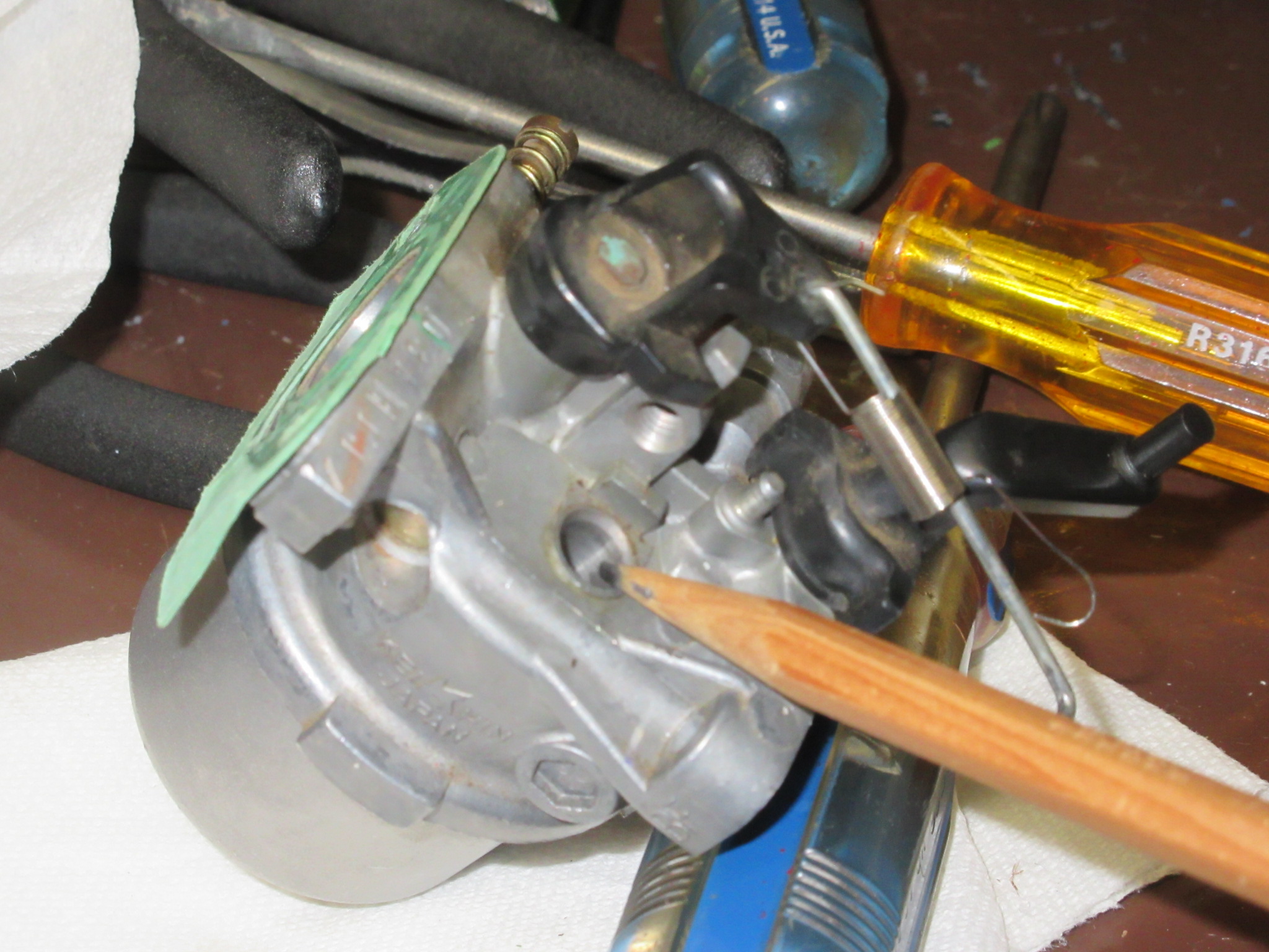
EX1000 Pilot Jet hole
Below: Pilot jet with two O Ring grooves: Is one missing or did they decide to save a few cents by installing only one?
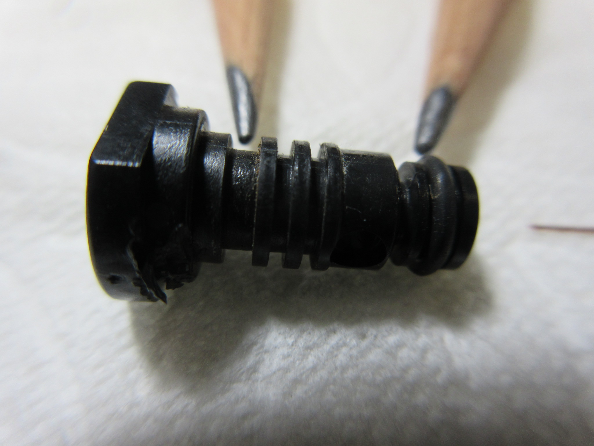
EX1000 Pilot Jet O Rings
Note the pencil on the left pointing to the upper O Ring groove. No O Ring! The right hand pencil points to the lower O Ring – there as it should be. This generator engine came from the Honda factory like this, the carb has never been opened up before.
This missing O Ring would have impeded tiny dust particles from eventually getting sucked into the carb past the pilot jet housing and this plugged up the tiny fuel metering jet holes in the carburetor body. Note the dust that had accumulated in the upper O Ring groove…Hard to clean out the clogged fuel ports in the carb body, even with a 36 gauge copper wire.
Cause: Either poor engineering or Quality Control at Honda. They failed to install a second O Ring in the grove provided. No one noticed. It took a while for dirt to infiltrate past that point and plug up the carb. Of course you cannot buy just the O Ring from Honda, you need to buy the whole jet assembly or a complete gasket set for the carb. A 5 cent O Ring from the auto parts store (and detailed cleaning) fixed it. This problem would have probably cost $150 to get fixed at the Honda dealer.
Not impressed. Great Honda marketing, crappy engineering or Quality Control.
Update on O Rings: Subsequent investigations have shown me that some of these EX-1000’s DO have 2 O Rings on the pilot jet housing. Not sure if these were added as an owner fix like mine or if some came from Honda like that. Unknown. I’d recommend checking yours and adding one if its not there.
Honda’s marketing slogan is aimed at the average homeowner/housewife whose only indication of “quality” is easy starting. “The One Pull Honda” LOL. That easy starting (important) is facilitated by a high energy ignition system (good) but that comes at a steep price (bad) – very high radiated ignition noise (a show-stopper for me, but invisible to someone running some lights during a power failure).
Now on to the “Inverter” technology below:
Those machines are basically gas powered, big Analog-to-Digital-to-Analog converters (using a Very expensive to replace PC board). The new, plastic-cased (unshielded), even cheaper-built generators use power “inverters” to make AC from DC from AC so I specifically avoided that technology for my applications.
Not sure what their waveform looks like on a scope but I wouldn’t be surprised if it’s “nice looking” 60 cps sinewave (with lots of nasty RF hash being generated internally at zero-crossings, digitizer trip-points requiring filtering down stream.)
Mr. Fourier tells us that all those fast conversion step-functions contain LOTS of high frequency noise stuff too. Smart guy! But that radiated ignition noise, unrelated to the ADA Inverter, is very bad, probably unfixable, zero shielding.
The common mode broadband hash on the power cable is particularly bad with this EU1000i generator – Mama Mia! Easily verified by running battery operated HF gear nearby, then connecting/disconnecting the power extension cable (antenna) at the generator end. Big difference in the 80/60/40/30 meter bands anyway. This one will take a lot of common mode power line choking to beat it down. Honda Fail – but their competitors are probably no better in this regard.

Honda eu1000i Inverter RF Noise Generator
Above: My buddy’s Honda EU1000i “inverter” generator to power his off-grid cabin (and ham radio gear in the cabin). A nice small generator; it starts reliably and seems to be fuel-efficient and is much lighter and quieter acoustically than my EX1000.
However it radiates LOTS of ignition noise, much worse than my unmodified EX1000. We have to charge batteries with it, shut it off, and then run the radios off the batteries so we can hear HF signals when we are up there. (note the kerosene lanterns for lighting during Radio Ops.)
It’s cheaper for Honda to build it with the simple inverter circuit board than to build a true AC sinusoidal alternator machine – the average homeowner would not realize or appreciate the difference. “Designed by accountants”. A decent “cabin generator”; they put some money into the muffler system design – it is very quiet. But again, Radio Ops beware!
Fun Fact: When the Zombie Apocalypse goes down, all those “inverter” generators are Toast at the first EMP burst. Those long extension cords make wonderful antennas connected directly to all that computerized inverter circuitry! Just when you need the generator the most: (SNAP! Smoke! Silence…..what just happened? !!)

Honda Eu-1000i Powering a GRC-109 and killing the receiver
Above: Giving it another try, this time powering a GRC-109 at a remote campsite. Get it as far away as possible! Awful ignition noise competed with the many CW signals we were hearing. At the end of a 100 foot extension cord oriented at right angles to the antennas it radiated a lot of ignition noise.
Inserting the SL-Waber 120 db common mode noise filter at the generator made a barely noticeable difference despite trying different filter-generator “grounding” schemes.
These generators start easily, primarily due to their high-energy ignition systems – but you pay the price. With the plastic case there is no real way to shield it. The next project is to tear it apart and try to shield the ignition system and wiring and install inductive chokes in the AC output lines like I did with my EX-1000. We’ll see.
Incidentally, inserting the SL Waber Wave Tracker EMI filter at the output did not cause the generator to stop producing AC like it did with my Honda EX-1000. Different exitation scheme that is decoupled from the load. At least THAT worked…..
Anyone else have any experiences with those powering HF receivers in the field? I guess I am just spoiled by using well designed “military grade” hardware rather than “consumer grade junk” that is on the market these days. But then again, it was “cheap”.
PU-181/PGC-1 Generator: Below is a photo of my favorite vintage generator (alternator). It is the PU-181/PGC-1 built in 1950 by Jacobson of Racine Wisconsin. TM11-943 applies. The PGC-1 was a field teletype system utilizing the TT-4(*)/TG Teleprinter system for wire-comms in fixed or tactical forward areas. Since the generator puts out 300 watts at either 120 or 240 VAC I’m sure it was used for every other sort of military need as well.
These things would be very handy. It is a 2-cycle engine generator, requiring oil to be mixed (16:1, SAE 30 above 32 degrees F) with the gasoline to lubricate the working parts. The engine develops 1.25 horsepower at 3600 RPM. It is very reliable and starts with the first pull, even after sitting idle for over a year.
The TM states that it will run for 7.5 hours at the full 300 watts output on one tank of fuel. When powering my military radio gear in the boonies running casual operations it will go for over a week on a single tank. Fill it up and go….no need to bring the Jerry can.
Except for a standard AC power connector which I installed, this generator has all the original parts from when it was built. Including the spark plug. It has a lot of mileage on it but still runs great. You just need to clean the carbon from the exhaust port every 5 years or so. It even runs fine on year-old gas. Dependable. I understand that an Autolite Part Number 2246 shielded suppressor spark plug is a good replacement if needed.
It’s a little noisy acoustically, sounding a bit “rattle-y” and it produces a bit of white smoke from the lube oil, but not enough to be a tactical observation concern. Its principal attribute however is its very effective RF shielding to keep nearby radio systems happy. The entire ignition system, including the spark plug is completely shielded. Lock washers everywhere. This thing is very quiet RF noise emissions-wise, a perfect campsite generator for field comms work.

PU-181 Generator to power the RS-6 Radio Set
Above: The PU-181 as set up ready to power the RS-6 HF CW radio in the boonies. Way more power than the RS-6 needs but you can also run the Blender at the same time.
There is another very similar generator for the GRC-9 and SCR-284 (PE-162* depends upon the model) that looks almost identical but it has an outlet box specifically to power that radio – I believe 120/240VAC is not available. The PU-181 will run all day on a tank of gas with a pretty good load. It will run all weekend with the type of radio comms I usually have going – it sips gas.

PU-181 Generator in the bush
Above: The Korean War-era PU-181/PGC-1 generator doing its thing out in the boonies. No problem with high altitude. Only a slight adjustment of the voltage control knob (feedback to engine speed) needed at 8000 feet elevation. Still started on the first pull after a year in storage – with old gas to boot. (Hint: Use the longest starter rope you can get on the shaft winder. 550 parachute cord is ideal. That long rope really gets the RPM up for awhile and the engine can’t help but start!)

PU-181/PGC-1 Gas Generator
Above: The PU-181 cranking out Watts to power my RS-6 radio at FOB Long Rock.
On lubricating the PU-181. The original manual requirement is 16:1 gasoline to 10-weight oil per gallon (operation below 32 degrees. 30 weight oil when temp is above 32 degrees.)
There were 2 different sized fuel caps (doubling as an oil measuring cup). My example has the smaller, 2 inch deep cup. Four of these smaller capfulls of oil per tankful of raw gasoline. These days I am using modern synthetic lube oil at 32 or 40:1 for 2-stroke engines.
Update: After 69 years of faithful service the selenium rectifiers(s) in the voltage regulator circuit started to fail. I replaced the assembly with 4 silicon diodes and a dropping resistor. For more detailed info on the PU-181 and that specific repair, take a look here: GENSETS for GRC-109, RS-1 and RS-6 sets

PU-181 Fuel/Oil Measuring Cap – Smaller, 2″ size
The above decal was added to late-production reworked units to clarify the issue of 2 different measuring cup sizes that were apparently fielded.
Here’s another fine little gas powered military generator: The Homelite XLA115/1/400
As far as I know it was not assigned an military PU-xyz model designator.
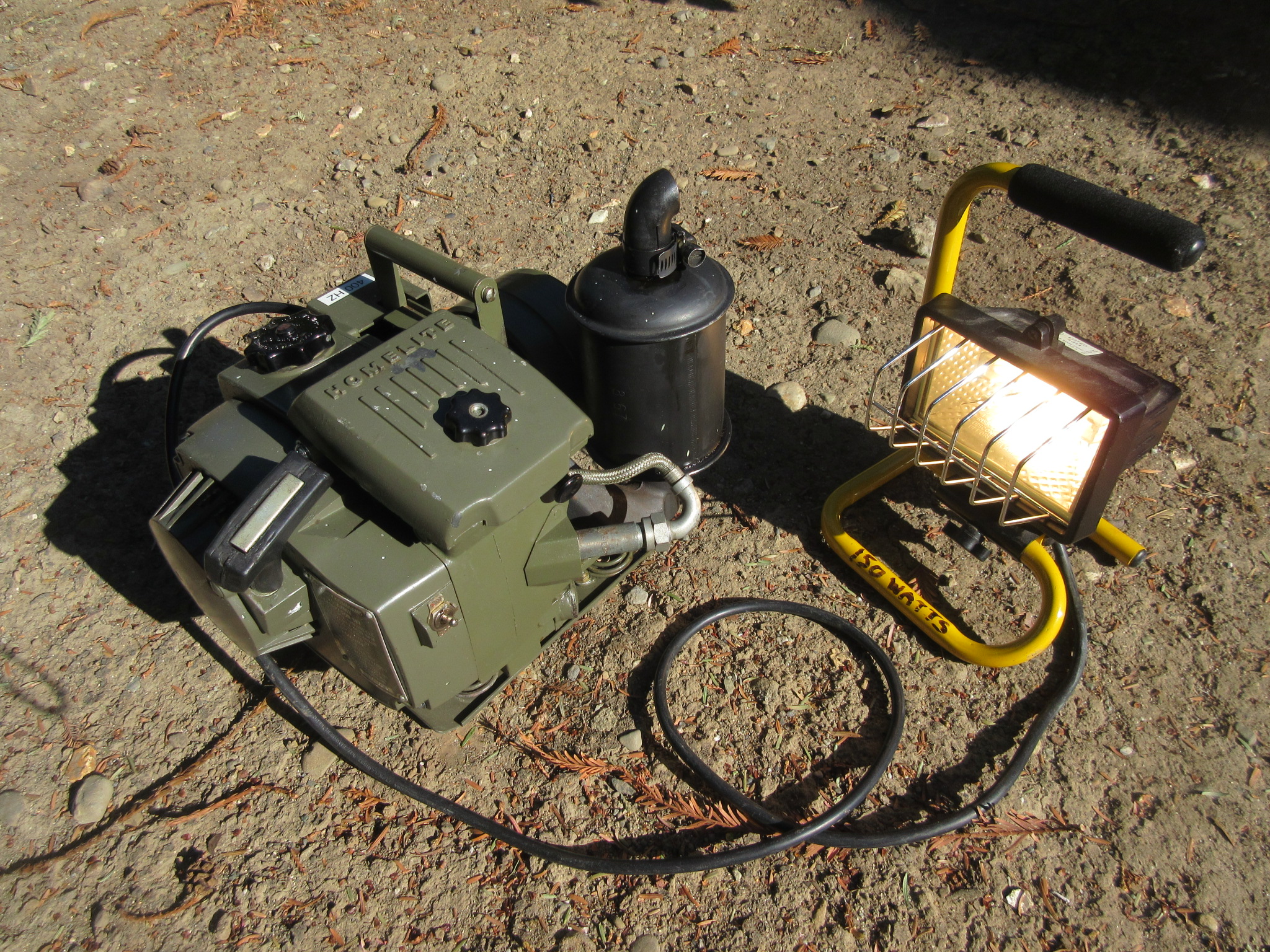
Homelite XLA115 400 cps generator
This little guy is rated at 125 watts, 115 VAC at 400 cps. It was designed to power military radios in the field, notably the AN/GRC-109 and the earlier RS-1 and RS-6 CIA sets that were designed to operate off 115 VAC with AC sources delivering power at between 40 and 400 cps.
400 cps chosen to reduce the amount (weight) of iron in the generator magnetics and also in the transformer cores of the radio gear designed to operate at 400 cps AC power. (Also common in aircraft equipment for the same reasons.)
With its simple, light weight, valveless two-stroke engine, it will also power incandescent lamps or any other resistive load not to include motors or transformer operated equipment rated for 60 cps power.
This Genset is conservatively rated like most military gear. Here powering a 150 watt quartz shop light – no problem. Note the completely shielded ignition system and all metal construction; it radiates no RFI ignition noise into nearby HF receivers. Honda take note!
It will run at full load for 1.4 hours on its internal fuel tank. It also includes a fuel selector valve that can select an external fuel source such as this 1 gallon fuel can. Very handy, that will run the generator for over 12 hours. The specified lube is SAE 30 weight oil mixed 32:1. I am using synthetic oil in the mix at 40:1 as a better alternative using modern lubrication chemistry.

XLA115 generator running from external fuel source
As deployed in a field Op powering the AN/GRC-109 at a remote Safe House:

XLA115 Generator in the field
It delivered 129 VAC to the GRC-109 at the end of a 50′ 14/3 gauge extension cord; 2 volt drop under Key Down loads. No ignition noise.
GRC-109 powered by XLA115 400 cps genset
I didn’t try to adjust the governor – the PP-2685/GRC-109 didn’t care!
The Put-Put 2000: Of course if you are in an “Improvise, Adapt, Overcome” situation and just need to generate up to 1000 watts of power to charge 12 volt car or deep-cycle batteries, the below item might be useful. Powered by an ancient Briggs and Stratton 2 horsepower lawn mower engine, it drives an automobile alternator. The engine came from a beat up, old yard-sale lawn mower that I used to cut the grass for an additional 15 years. Mower wore out, engine kept on running. It never made it to the Go Kart I had envisioned.
The alternator is rated at 63 amps and there is more than enough engine power to produce that. The alternator internal voltage regulator holds the charge voltage at around 14.7 volts; when the battery rises to this voltage the field winding current is automatically reduced to prevent overcharging.
This is a new and improved model of the earlier PutPut 1000 that used an old relay-type voltage regulator. This version features a Delco Remy “one-wire” alternator with the built-in voltage regulator for improved reliability. With the belt ratio chosen, the engine runs at low speed but it still sounds like – well – a lawn mower – perfect acoustic camouflage for your clandestine suburban operations.
The pulley ratio chosen also prevents the engine from stalling if the load suddenly increases – not much of a flywheel here….It includes a field current switch to shut off the field winding for easy starting (your rope pull does not also generate power) and an external Ammeter. (Yes Virginia – it does radiate a lot of ignition noise! But you are not playing with radios while you are mowing the lawn, are you.)
This contraption sits on a 3/4″ plywood base on 4 pieces of 1 inch rubber coolant hoses, split and bolted to the bottom for vibration control. Simple, effective, does the job. Made in the USA !
Introducing the new and improved “Put-Put 2000” from Hillbilly Engineering.
From Murphy’s Laws of Combat: “If it’s stupid – but works – it isn’t stupid”

A belt guard is next. I also need to redesign the belt tensioning contraption.

Below, here it is earning its keep out behind the Safe House.

Lawn Mower Generator charging 12V battery
STILL needs a belt guard!
Hi Tim, I have a PU-181A/PGC-1 generator nearly identical to yours. Mine is the A version without the rectangular binding post box on top of the generator. My binding posts are on the end of the housing, around the socket. Anyway, I’m having a problem with the selenium rectifier located under the shield at the engine end of the generator. The rectifier is crumbling and will have to be replaced. Does yours still have the original? I was thinking about replacing it with silicon diodes and a power resistor but I’ll have to fabricate screw terminals like the old selenium has. I agree that the shielding is well executed on this little generator.
Andrew, KC2UOY
Hi Andrew – Well, mine has the original selenium rectifier assembly. I always keep an eye on it but so far, so good. I think replacing it with 4 beefy silicon diodes should be just fine. I don’t know how much the solenoid coil draws so I’d just put “hi-current” diodes in there a few amps or so rated. Should not need any series resistance but you would probably have to readjust the governor to compensate for the lower forward voltage drop of the silicon diodes versus selenium. Let us know how you do with that. Also, have you found a modern spark plug that you like? Or is yours original like mine?
Thanks for stopping by!
73, Tim
got a simulair generator, a PE214, used to power up a public addressystem TIQ-2
seleniumcell replaced by silicon diodes and running fine, indeed readjust te voltage control to run the engine stable on 60/50Hz current drawn is in the low order below 1 amp. so a moderate diode will work. I put in a bridge with 4 times a 1n4007 and it works
fb. sparkplug is a original one, also have the PE210 12Volt dc for charging the batteries and the PE 162 for powering up my BC1306. enine is the same, generator different, but
exchangeble with each other…..
Hi Andre – thanks for the note…They are good generators in the same family and they are handy and versatile. Let’s keep them running!
Thanks for the info on the diodes – probably their only weak point due to age-ing….
73, Tim
Hello Andre,
re: silicon diodes
I also need to replace my selenium rectifier (s) with silicon diodes.
How was that done? What was used ? Is there a simple schematic ?
Can you help?
thanks’……………..
PE-214-A
PE-214-B
PU-181
Good info on the Honda gensets. I was unaware of the RFI issues. I was thinking about getting one but now I am having second thoughts. I always enjoy reading your website and learn something every time. Thanks for keeping up a very informative site.
Best
Kim W4OSS
Hi Kim – Thanks for checking in.. This Honda is otherwise a good Genny but RFI noise like this drives me nuts. For the cost of these things they could have done a little better job. But the accountants would have none of it to keep some random Hams happy with it. I would imagine their competitors have similar problems…
Up above around 50 MHz the noise is reduced so for a VHF/UHF setup (especially FM) you would be OK; otherwise, heads up.
Thanks for visiting the website!
73, Tim
Hi Tim,
Awesome website. Couple comments on this post. First, as an engineer you know that all products/systems have a set of design constraints. I’m pretty sure that RF interference/shielding is not high on Honda’s constraint list, unfortunately for us. Also, if you think the Honda is bad, you should see the Chinese Honda knock-offs.
Second, the modern 2-stroke oils of today are light years ahead of the oil that those GI generator engines were designed for.in the 1940’s. If you use a modern 100% synthetic like Red Line or Bel-Ray and increase the mix ratio just a little, you will likely eliminate all smoking during operation. For example if the manual calls for 20:1 mix ratio by volume you should be able to run at 24:1 or 30:1 with no impact at all. On vintage dirt bike engines they typically run 36:1 or even 40:1 when the manual is calling for 20:1. Just some things to think about. Please keep the posts coming! Thanks!
Hi Pete – thanks for checking in. Hope you found some of this stuff interesting anyway…
I have run synthetic lube in my old dirt bikes and chainsaws, it works fine and I really need to switch the old genny over as well. A task for this summer.
Roger on the modern genny’s; the cost constraints drove the product design which is just fine for the average homeowner application. I’d get another one. But it is a cautionary tale for use with HF radio receivers as I found out. Some people claim no problems (Hmmmmm!!) when using the EX1000 or Eu1000i with radios but that is certainly not my experience with these two.
Yep – those Harbor Fright knock off’s must be a real (though short-lived) adventure!
Thanks for stopping by! Tim
Thanks Tim. One thing I forgot from my post last time. I noted from one of your earlier posts that you had run old gas in the genset engine. From your posts I believe you live in California. As you know the gasoline in California is homogenized, pasteurized, neutered, and has three scoops of horse manure in it per pound-mass in lieu of the ASTM-mandated two scoops. Ha As a result, in my experience this gas goes bad FAST, much faster than it used to even just a couple years ago; in fact I’ve had it go bad in as little as two weeks. I lost a carb from my lawn mower (clogged up with varnish) and I’ve had to clean at least one dirt bike carb due to varnish and gum. So I am a religious user of Sta-Bil now. Just something to watch out for in your Kalifornia gas. By the way an old Crock Pot filled with a 50-50 mix of Yamaha carb cleaner and water works great for dissoloving the crap in ditty carbs on small engines. Fill it up, drop the carbs in, set the cock pot on High and after tt starts simmering, let it simmer about a half-hour, then blast out the passages with compressed air. Works every time. Stinks to high heaven so do this outside and don’t use the wife’s crock pot. Ha Get an old one from Goodwill for three bucks. Thanks! Pete
Hi Pete – Well I don’t seem to have problems with “old” gas in my applications. When done, I always run the PU-181 carburator and fuel line dry upon shutdwon (even in motorccles) so there is little to turn into sludge. I also keep gas in sealed cans so there is no oxygen exchange or evaporation problems. Even with the Kalifornia mandated Unicorn Pee and an absense of anything flammable in our fuels…I have also used Sta Bil and I don’t see any real difference with/without it. I also don’t know what its’ chemistry is so I am somewhat skeptical of the “marketing” without the results of controlled experiments.. In a full carb bowl/fuel tank with an atmospheric vent, sure, evap problems and sludge. (transfer filtering is manditory during refueling) .. Maybe I’m just lucky…
But good ideas about boiling out sludge with your solvent…
Tim
I have this same generator with the City of Los Angeles sticker, just like in your picture. I picked up my EX1000 from HamCom in Plano TX. The guy I bought it from said be bought it at Dayton. How old is your EX1000?
Mark N5RFX
Hi Mark – I got my EX1000 used, from a guy who bought it new in 1997. The Honda owners manual is dated 1993 so they probably began production in the early 1990’s. Other than that I don’t know – but mine is at least 21 years old. The “new” price was $870 for this one.
Love your site Tim, I have a HONDA eu 2000 I used on MARS HF Ops with no noise.
NO ” 1 Crank and GO” 3 or 4 if its warm much more cranking and if the oil is cold lots of cranking
George / N1EZZ
Hi George – Good deal, glad yours is quiet…Ignition noise can be a real pain..Yep, cold oil can make things interesting.
Thanks for stopping by & thanks for your service!
BT
AR
Hi Tim,
Always great to see you at the MVCC meets, hope your doing well. . Had a super time talking
and meeting old friends and looking at all the stuff. I sold a few working radios, as you know I enjoy repairing many of the old military rigs if possible and watching the eyes of the
to buyers say (IT STILL WORKS.
Great write up on the EX1000 Honda, which I have one. My question is under load
the AC voltage reads about 90 volts AC. How can I increase voltage.
Please your thoughts.
Keep Well my friend– my plans are being at camp Plymouth in September , God willing,
hope you make it as well.
Keep Healthy
Jerry F
WA6BXV MVCC CW freq 7.032 khz
Voice Call sign on 51.000 is (HOTDOG) why not !!
Hi Jerry – Yes! Good to see you at MVCC too, albeit briefly. Great event…
EX1000 voltage output. Good question! The manual does not address any adjustment capability and I really don’t understand how its regulation and field system works, the manual does not even mention it. However the schematic shows a pair of L/R/Diode networks “floating” inside the generator “windings’. That in addition to a parallel LC “Condenser” network that somehow develops a field current. So maybe see if you can access the generator innards and see if those diodes are OK or maybe a shorted cap. Mine seems to be OK but again, I can’t figure out how its regulation system actually works. Thanks for visiting, see you around…Tim
Mated a honda weedwhacker 1 HP 4 Stroke to a great Planes Aero bolt on coil (for a Volkswagen engine homebuilt plane).
Weight 10#. Did 4 trips to Bermuda in a sailboat with it.