
UPDATED 1/21/2026
The PRT-4 and PRR-9 worked together as an attempt at a simple, lightweight Squad radio, albeit one-way. First fielded in Vietnam by the U.S. Army in March 1967, the idea was to extend an infantry platoon and/or squad leaders’ command and control beyond verbal, hand signals and personal contact communications.
They were initially found to be very useful by Army Special Forces (Reference 1) and they were utilized by Navy Underwater Demolition Teams and the Marines as well.
Interestingly, the recommendation for the adoption of this system, its tactical employment and its replacement of the PRC-6 radio was made in a 1964 document. That one was written by Colin L. Powell, then a Captain at the US Army School of Infantry at Ft. Benning. Yup, same guy.
Shortly before the Dak To operations in November 1967, the 173rd Airborne Brigade received these new radios with the objective to replace the Korean War vintage “Radio Set AN/PRC-6” (not to be confused with the WWII SCR-300 “walkie talkie”). The PRC-6 proved to be too heavy and cumbersome in the jungle. By late 1967, the PRC-10 had already “come and gone” from Line units and the PRC-25 had become well established – but not as an individual soldier or fire-team communications set.
Using this new system, and depending upon circumstances as described by Captain Powell, the platoon and some squad leaders carried both the transmitter and a receiver. Some squad leaders or individual riflemen carried only the receiver for one-way commands or advisories from the platoon/squad leader.
The receiver was clipped to the M-1 helmet or it could be hung from LBE suspenders if necessary. Units of the 173rd that used them in combat initially reported that they worked quite well. At the same time, soldiers complained about the lack of a capability to respond to orders since they lacked a transmitter. Go figure, but it was still better than shouting or hand signals at night.. (Reference 3).
During the conceptual design phase the USMC insisted on a single unit transceiver, ultimately resulting in the frequency-synthesized PRC-68 which arrived around 1975.

Above, a well-worn PRR-9 Radio Receiver (right) and the PRT-4A Transmitter with its telescoping antenna retracted. Shown are the 15 volt BA-399/U Battery for the transmitter and the 6 volt BA-505/U for the receiver. Note the 1981 and 1982 date codes on the batteries.
As a transmitter-receiver pair, they are sometimes designated as the PRC-88 depending upon the document. Reference 117 of 1976 states that the PRC-88 was ONLY the experimental, combined transmitter-receiver set seen below. The Squad Radio program was very much in flux at the time. (However from the later Field Manual FM 7-7, March 1985):
“AN/PRC-88. Some units may be equipped
with the AN/PRC-88 squad radio. The squad
radio consists of two pieces of equipment, an
AN/PRT-4 transmitter and an AN/PRR-9 receiver.
Both the transmitter and receiver have
preset crystal-controlled frequencies that can be
changed as needed by the battalion communications
platoon.”
Total system cost was quoted at $1044. (Reference 117 cites the cost of the Transmitter at $139, the Receiver at $107.)
The FM voice transmitter could operate on 2 separate crystal-controlled radio channels between 47 and 57 MC. Channel 1 set at 450 milliwatts output, Channel 2 set to 50 – 250 milliwatts output (selectable level via a resistor change). Channel 1 planning range was 1600 meters, Channel 2 was 500 meters. (TM 11-5820-549-35). Feedback from Vietnam noted approximately 100 meters max in the wet jungle.
The 2 frequency channels for the transmitter were for use at the higher powered (longer range) for comms up to the platoon and the low power channel for a squad level (short range). They need to be kept within 1 mc of each other for alignment purposes.
I can find no reference to a crystal kit to re-channel these radios although there was a CK-50 set for the receiver crystals. There is a test set provided for changing frequencies. (ID-1189/PR Indicator, Channel Alignment.) At the time the Army had not decided upon a required production number for radio sets and the need for multiple channels for all or only some radios in units was not settled. (Reference 117.)
The soldier set uses a socketed CR-81/U crystal (two per transmitter) and one for the receiver. The few sets that I have seen are all on 51.0 MC which is where I use mine on the 6 meter Ham band. Interestingly the older AN/PRC-6 hand held sets intended to be replaced were shipped from the factory crystalled for 51.0. No coincidence here.
I power my transmitter with two 9 volt batteries connected in series, mounted inside a defunct BA-399 package. The internal voltage regulator for the low power stages in the PRT-4 can handle the excess 3 volts with no problem. The PA transistor is powered by the higher voltage directly. (A small series dropping resistor would be reasonable at 18 volts however.) Mine works fine without one.
I lashed up four AAA batteries for the receiver absent a viable BA-505/U. The BA-505/U consists of four N sized cells in series for 6 volts. (I have also used a 9 volt battery in series with a 200 ohm resistor to power the receiver.)
Planned battery life for the issued BA-399/U was 35 hours, the BA-505/U was 14 hours. A magnesium receiver battery (BA-4505/U) was also developed with a planned life time of 28 hours.
This transmitter, serial number 21232 bears a contract date of 1967; it was made by the Delco Division of General Motors Corporation. The transmitter antenna is a black-oxide camouflaged telescoping whip, 24 inches long when extended. The BA-399/U battery box clips on the bottom of the transmitter, its bottom is left open probably to save weight and maybe to drain water (!). Some transmitter battery boxes also have lightening slots on the front and back. More on that later.
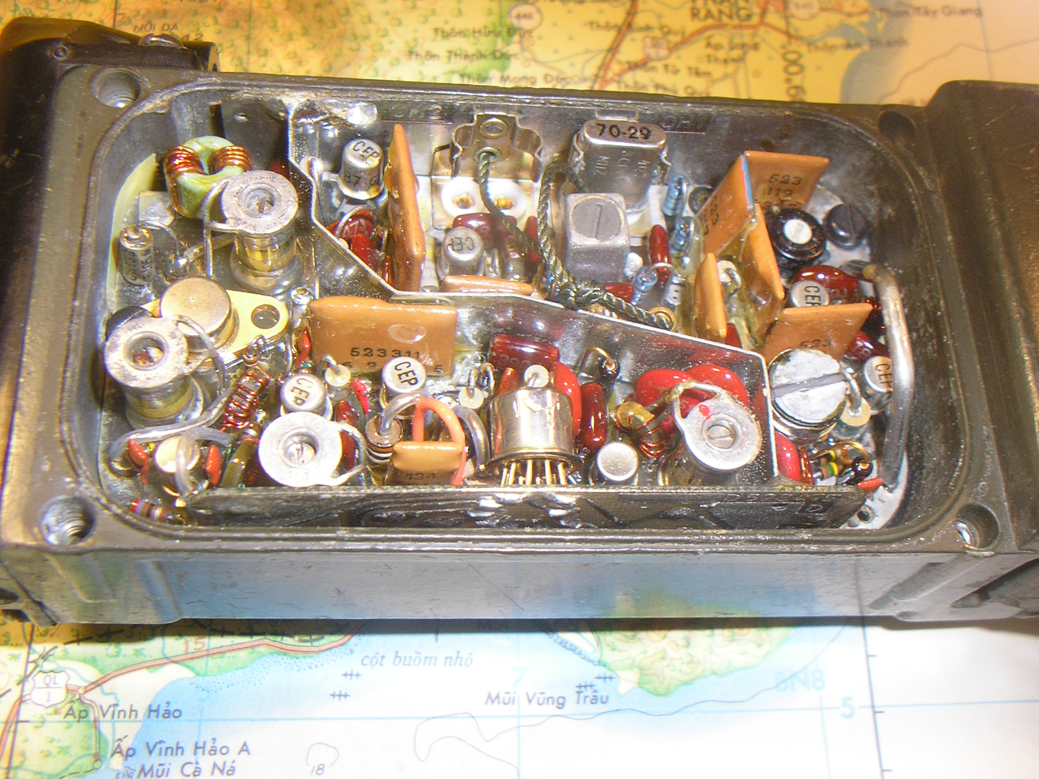
Above, the circuitry inside the PRT-4A Transmitter. Note the crystal for Channel 1 (Date code of week 29, 1970), the missing crystal for Channel 2. The silver can in the center foreground is an early integrated circuit consisting of 4 transistors 2 temperature compensation diodes and 5 resistors.
This device provides for the 150 cps tone oscillator, emitter follower and 2-stage speech amplifier. This is reportedly the first use of integrated circuits in a US military field radio. The circuitry has been moisture-fungus proofed using clear lacquer and a gasketed cover plate.
Meanwhile, back in the jungle (er, rain forest), the set’s shortcomings became apparent. The receiver antennas often snapped off on underbrush so the soldiers taped them to the plastic helmet liner to protect them. This reduced the potential range of communications. Attaching the receiver to the LBE suspenders also reduced the range since the steel helmet was designed to be a part of the antenna system – sort of a “ground plane” – but removing it from the helmet also reduced its range.

Above, the 14-transistor PRR-9 Radio Receiver, also made by Delco, mounted on a standard M-1 Helmet. It can mount on either side – on the left most likely for a right-handed rifleman. In this photo the receiver employs an “ersatz” wire antenna. This might reflect a typical field repair since the issued AS-1998A/PRR-9 antennas were often broken. The plastic spiral “trumpet” directed the sound from the speaker directly to the soldiers ear. Alternatively, the H-269/PRR-9 earphone was supplied. It plugged into a weather-protected jack on the receiver, presumably for use when the receiver was hung from the LBE suspenders vs helmet installation.

Above, the operating control of the receiver. The phone jack has a spring-loaded dust cover. The power ON knob also functions as the volume control. Upon initial turn-on the radio is in the Carrier Squelch mode. Interestingly, rotating this control fully clockwise, it stops at a “detent” which disables the carrier operated squelch. The control then continues to operate as a volume control. The squelch threshold control is an internal potentiometer not accessible by the operator.
The original system was prototyped in 1964 as transistor technology matured. However, the system did not include Tone Squelch as that system was not in use at the time. Later on, the PRT-4A was developed and it did include the 150 cps Tone Squelch to make it compatible with the new VRC-12/PRC-25 radios as they were coming online. The original PRR-9 receivers used a Carrier Squelch and later on the PRR-9 (XE-9) model was fielded that did include a Tone Squelch decoder.
The PRT-4 Transmitter incorporates a 2-position channel switch and a rotating, spring-loaded mode switch which also serves as the Power On switch. Designed to be held primarily in the left hand while the right hand was holding a weapon, depressing the switch with the left thumb placed it into the voice mode. Rotating the switch in the “Tone” direction, the transmitter produced a 1200 cps tone (in addition to the 150 cps squelch tone with the PRT-4A), ostensibly to communicate simple, pre-arranged messages without speaking. “Three beeps: Return to the rally point”.
Using FM technology, my set produces excellent quality, noise free audio. The microphone gain is very high, enabling “whispering” by the squad leader and the receiver gain is of course variable. As a pair, they sound great, not bad for 65+ year old technology.
During field experiments on camping trips to the mountains, the pair has produced good comms in wooded, open country at ranges of approximately 1 mile (as designed). That was with Channel 1, 450 mw output. About the same range as my UHF “FRS” walkie talkies in practical camping usage.
When paired with an RT-70/VRC-7 for example it is a very effective short range “patrol” setup for local ops. We exercise this combination often on camping trips.
The receivers were also quite fragile as a result of efforts to keep them lightweight. One significant issue caused by the intent to save weight; both the transmitter and receiver batteries were not fully enclosed. They are exposed to the elements and quickly degraded in the mud, rain and humidity.

Above; the PRR-9 rectangular speaker outlet and helmet clips are visible. The BA-505/U is a 6 volt cylindrical tube battery containing four N-sized cells in series. It was completely exposed to the elements. This receiver, serial number 7081 was refurbished at the Sacramento Army Depot in Dec 1968. It had seen a lot of use during its military service.
Navy Underwater Demolition Teams and USMC (presumably Force Recon) did utilize these sets in early 1968 while conducting hydrographic surveys in Vietnam. Utilizing the experimental “Aqua Darts” to transport swimmers performing Recon and beach and shallow water mapping missions, the AN/PRT-4 / PRR-9 pair was their emergency communications asset. (Reference 97).
The Aqua Darts were powered “sleds” pulling the operator along while equipped with navigation recording devices to correlate hydrographic data with the local terrain. The radio sets were presumably provided with significant water-proofing as they were constantly wet in sea water which would immediately kill them.
At some point, the US Navy had the pair adapted and repackaged to include both the transmitter and receiver into a single unit. This was possibly driven by a requirement the Marines or Navy UDT/SEAL’s had developed. It was also confusingly designated as the PRC-88 but it did not see widespread use beyond evaluations as far as I can determine. The family resemblance is apparent. Photo from DH4PY. http://www.greenradio.de/e_prr.htm

In the end, the radios didn’t hold up to the rigors of jungle combat very well. One-way comms were clearly problematic so they began being left behind as operations were launched. They were apparently then used in rear-area security work and would have been handy in that role – freeing up better tactical equipment for combat. Seemed like a good idea at the time. At least they were fairly light weight.
Eventually the PRC-25 and PRC-68 (USMC) essentially replaced this system although neither was designed for an individual infantryman as a hand-held “intercom”. The PRT-4 / PRR-9 was still listed in FM 24-24 Radio and Radar Reference Data printed in December 1983. Status was listed as “Standard A”.
“The current inventory item is available to fulfill operational requirements.”
Epilog: Even today the quest continues for a viable squad or rifleman radio. As technology evolves the need continues for something that meets everyone’s requirements where the RF spectrum is now contested terrain. From your Mom sending you an FRS “bubble pack” radio from Amazon to various COTS and semi-COTS FRS/GMRS UHF clones out there as well as purpose-designed “Mil Spec” radios. These include the PRC-148, 152, 153, 154, 163 and others..
This includes offerings from domestic and foreign sources. Some to include built-in encryption, GPS, frequency hopping and software-defined networked wonders. It seems the ChiCom’s Baofeng and other offshore vendors are supplying large quantities of cheap “ham” radios to insurgents worldwide to meet their needs. Photos abound.
Where will it lead?
HI Tim, just received a PRR-9 in the mail today, a working unit on 51. Contract date 71, Varo INC manufacture. Made a temporary connection to a 6v gel cell with test leads to play with it, neat unit, amazing how light it is. Tracking down a Tx now and waiting for batteries to arrive to rebuild. Thank you for the great information.
73
K1HF
Hi Mark – Good deal…A very interesting “set” that seems to have filled a need but then bypassed. Impressive design and packaging but keeping it lightweight exposed the batteries and that apparently became the problem. Nonetheless, they work great. Have fun with it!
Hi Tim, This is what I use for comms around the Dayton Hamfest on 51.0. I took the speaker horn off the PRR 9 and zip tie it to my day pack shoulder strap. I use the earphone. Makes for a very light weight receiver. I carry the PRT 4 in my hand or back pocket. This works great as an “intercom”. 73
Kim
Hi Kim – Good idea! I wonder if the troops did a similar thing – The earplugs were available and it’s otherwise a bit clumsy on the helmet..
These little sets actually sound great and are very handy. I set mine up for kids to play with during veterans events – good fun.
Love your call sign !!
73, Tim
I have repaired several of these sets, given several away at radio club events and still have several I will probably never get around to use.
Batteries
I think the transmitter battery was 12 V. I have clipped two transmitter battery holders together to hold 10 AA-size NiMH rechargeable cells. I have yet to test operating time of this battery combination.
I have used tagged rechargeable N-cells for the receivers. It is difficult to get the cells in the casing and close the top.
Receiver sensitivity
Properly aligned, the receiver is very useful as a guard set for checking incoming signals – as I recall, less than 1 uV for 10 dB S/N.
73 de Brian, VK2GCE
Hi Brian – Some good adaptations there…The BA-399/U that I have is marked 15 volts, but close enough. The transmitter includes a voltage regulator for the low power stages to improve stability with a sagging battery. The VR pass element nor the PA transistor in mine gets noticeably warm with 18 volts from the two 9 volt batteries in series, and they in the box fit nicely..
I agree – they are handy little sets that work quite well. Cheers! Tim
I used the prc-88 combo, Since we didn’t use helmets just soft patrol hats, helmets just for jumps. the receiver was hard to attach to web gear and I could yell further then the radios reached in the mountains. also carried the prc 10 and prc 25 loved the 25 hated the 10.
Hi Mike – Thanks for your observation! Can I ask when and where? I’ve found basically nothing about the PRC-88 “pair” besides that one photo. Someone went to some trouble to design and build it!
Thanks for visiting my website….Tim
Hi,
I am a Marine and served in Viet Nam, in late 1968-1969. I was tech in a Comm unit. My group was given a chance to test the PRR-9. It sounded like a good idea.
The unit determined that the equipment had limited range and only line of site reception. We also thought the headset was a little heavy to be clipped on the helment. After testing, I never saw the device again.
Hi Kevin – Thanks for the report! “Ground Truth” as we say…
Yep, seemed like a reasonably good idea but yes, short range and a bit heavy and clumsy on the helmet. Also the One Way comms left a lot to be desired! They got mixed reviews when compared to “no other option” but in the end seems they were relegated to rear-area service if even that.
Thanks for visiting Marine!
S/F Tim