
UPDATED 3/12/2024
Another favorite Black Radio is the RS-6 set.
(RS-6 = Radio Station number 6 per Central Intelligence Agency nomenclature.)
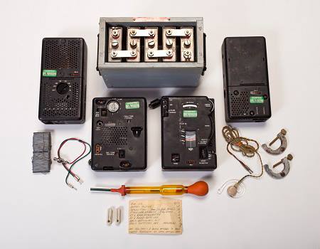
“This radio set (below) and battery was hidden in Western Europe in 1961 and was not recovered until 1990. Had its use been necessary, the operator would have activated the unit by adding water to electrolytic powder and poured the solution into the battery.” www.cia.gov/legacy/museum/artifact/rs-6-agent-radio-set
Some other sites go into the technical details of this set but I will mainly focus on general description, known history, my observations and actual operation in field environments for now. Probably more than you ever wanted to know. A work in progress.
It is both an historic and (these days) a fun little camp radio and works equally well from hotel rooms, tents, hide sites, cabins, palapas, safe houses or anywhere with a nearby barbed wire fence or a tree for a clandestine wire antenna.
Perfect for Secret Squirrel missions.
If you ask me a question that has a classified answer, I will reply:
“I don’t know”.
If you ask me a question and I don’t know the answer, I will reply
“It’s classified”
Got it? ;0)

Below: Same rig, different place. Like the AN/GRC-109, this set has a Cool Factor 37 db higher than any plastic ricebox ever made by KenYaeIc. Today’s “appliance operators” and Smart Phone Zombies will surely turn up their noses at this set. They would never Get It..

As a classic Black Radio, this long range HF morse code set was used by the CIA, partisans, Special Forces, Recon units and the U.S. Air Force Strategic Air Command. Anecdotal evidence has them being used in Southeast Asia, Europe and Central America; they were probably used “everywhere”. They are quite EMP resistant.
Early History:
From a declassified CIA report:
“[REDACTED] reviewed the history of the RS-6 and the requirement for which it was designed and procured; circa 1949-1951. The set was designed as a manual keying, low cost replacement for the WWII SSTR-1. At the time Agency plans called for large scale stay behind activities and strategic reserve/war planning programs….” (Reference 59)
Under the initial contract the first units started arriving in early 1950 when the successes and value of OSS operations in WWII were still in mind. Production moved very quickly.
In a 27 June 1950 internal CIA memo, the Communication Division Chief was directed to make 1225 RS-6 sets available at 9 different locations for issue to agents along with 1205 RS-1 sets among others. (Reference 73.)
(North Korea invaded South Korea 2 days earlier on 25 June 1950.)
A CIA memo dated 10 Sept 1953 noted that in June 1952 the USAF had indicated an interest in the RS-6 and asked the CIA to procure 1500 sets for them. (Reference 60, last page). This reference, et. al., clearly indicates that the RS-6 was originally developed as a CIA set that was later adopted by the USAF rather than vice-versa as some have surmised.
However, by the mid 1960’s the actual deployment and usage rate was less than anticipated so a large surplus of RS-6 and RS-6A sets were eventually on hand. That included 3542 sets in CONUS locations plus an unknown number in OCONUS stocks, plus OCONUS cached or otherwise deployed sets. It is not unusual today to find fairly pristine examples. Procurement costs were approximately $487 per set, “FOB Chicago”, (most certainly Motorola) costs probably depending upon contract date.
The RS-6 and RS-6A were declared obsolete and excess to CIA inventory on 10 May 1967 and recommended for disposal by destruction. Destruction to prevent any from later “turning up in locations embarrassing to the Agency” since they were easily identifiable as CIA equipment. (Reference 59).
How so many appeared in civilian hands later on is not known. Those probably came from US military units and/or allied nations’ excess stocks. How this CIA equipment appeared in US military (aside from the Strategic Air Command) or allied unit inventories is so far unknown to me.
The 1967 CIA Equipment Board Minutes (Reference 59) also noted that the USAF had “a number of years ago” discarded as obsolete the RS-6 sets that they had purchased. Those 1500 excess USAF sets may have been the source of many of today’s examples.
A recent 2014 E Bay sale (WHAT ???!!!) revealed that a complete RS-6 set was found in the attic of a building in the town of Tarrenz in the Tirol region of western Austria. That communications cache included several one-time pads, a complete set of encryption/decryption materials written in German (the predominant language in Austria) and related items in addition to the complete RS-6 set. The cache included large NiCad batteries, antenna components, tools, an earplug, radio operating instructions and spare parts.
It was placed in Austria in 1961 apparently by an Austrian citizen, agent code named “GRBLAMED-31”, a member of a team code named “GRCROOND”. This was part of an effort to train, equip and support Austrian “Stay Behind” citizens in resisting a presumed Soviet invasion further into Western Europe.
This was part of a larger effort by western governments, including some “neutral” governments, to be prepared for possible Soviet occupation, a situation most of them endured under the Nazi’s. They were code named generically as “Gladio” units depending upon their respective countries programs.
These radio caches were established in the early 1950’s to also provide communications for “E&E Lines” (escape and evasion routes) from eastern to western Austria and nearby countries. There were six known (FOIA reported) RS-6/RS-1 communications caches in Austria in 1961. (CIA FOIA declassified reports, Project GRCROOND, Reference 48).
One reference indicated that the communicators were to perform “engineering tests” every 4 months to verify that the equipment was working. (Reference 81)
By the way, Soviet disinformation propaganda had a field day with sinister stories about the “real purpose” of these European stay-behind organizations once their presence became known to the general public. Vladimir Lenin’s “useful fools” in the West ate it all up.
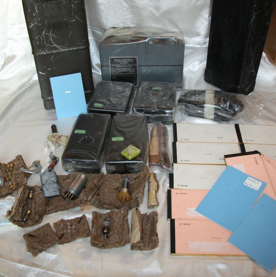
Above: Contents of the equipment cache as found in Austria. Note the five RS-6 components wrapped in clear plastic, the printed crypto materials, a big NiCad battery, spare vacuum tubes for the transmitter and receiver, power supply vibrator, antenna wire/insulators and the cache/burial containers. Photo courtesy of Richard Brisson at www.campx.ca Many thanks to Richard for sharing his amazing acquisition.
Note: Four of the above units (as well as the CIA’s recovered cache set in the photo at the top of the page) have the “Green Stickers” on them. There has been some discussion about those – and one line is that (only?) the Strategic Air Command radios had them. The above photos of clearly CIA-origin gear seems cast doubt on that theory.
As a matter of routine “Tradecraft” the radio equipment itself, the communications plan/crystals and the associated encrypt/decrypt materials would not all be cached in the same location. They would preferably be cached in 3 separate locations. This to thwart the enemy who finds a complete system and then uses it against you in an OPDEC (Operational Deception) effort. It is not known if the above photo shows the complete system as originally found, but the two containers indicate it may have been part of a larger cached system.
The CIA document (EUCA 61-966 Dispatch, Reference 48) details the inventory of this exact cache (by component serial numbers). The cache also included a complete RS-1 set (predecessor of the nearly-identical AN/GRC-109), GN-58 hand cranked generator and other materials which were apparently not included in this E Bay sale. This reference and related ones clearly show that radio operators working as Stay Behind agents in Austria were trained in both the RS-1 and RS-6 radio sets. From a mission perspective their training/operation is essentially identical for both sets.
As mentioned above, the RS-6 was a direct replacement of the SSTR-1 set as used by the OSS in WWII. The development of sub miniature vacuum tubes enabled the technology leap to the much smaller RS-6 although the functionality and design similarities are obvious. Other direct blood relatives of the SSTR-1 are the RS-1 and GRC-109 sets.
The complete radio set is packaged in 4* small, light weight units to make concealed carry by one man possible, something not easily done with its predecessor, the RS-1 or the later GRC-109. The complete set of 4 units plus accessories weighs less than 16 pounds.
The set operates from 70-270 Volts, 42-400 cps AC or 6 volts DC from the battery of that captured T-54 tank or SCUD missile launcher. If AC power is available, it can also charge that captured vehicle battery.
It could also be powered by a hand-cranked DC generator GN-58 with a suitable cable modification. The manual states that the GN-58 cable must be modified by replacing the radio-connector with a 6 contact female connector (which comes as an accessory to the RS-6) which then plugs into the RA-2 or RA-6 filter assembly.
There may have been a stock cable for this purpose but the manual does not address that by part number. A suitable connector was supplied in the spares kit – but it was up to the operator to install it. NOT good-to-go. (That connector is probably the black cylindrical object to the left of the power supply module in the above photo.)
I have recently learned from the above cache that there was a power supply regulator unit, the RA-2, that was also* available at some point in time. (One can be seen in the above cache photo as the item wrapped in clear plastic with the white tape around it.) This allowed the transmitter and receiver to be directly powered by the GN-58 hand generator without needing the modified cable, the RP-6 AC power supply or the regulator/filter unit RA-6.
This is the same function that the CN-690 provides for the RS-1 and GRC-109 sets. Wide voltage/frequency options and versatile power connectors made the RS-6 usable worldwide.
Interestingly, as in Austria, the Netherlands was also a user of the RS-6 for their own “Stay Behind” operations in case the neighborhood went down hill again. They made a couple of really good modifications: One was replacing the fragile interconnect connectors with more standard DB-9 connectors. (Those connectors became available from Cannon in 1952.)
They also replaced the problematic vibrator circuit with a transistorized power supply built into the existing power conditioning unit when that technology became available. Very smart.
They did not just replace the vibrator with a solid-state oscillator. It is a ground-up redesign using 2N1544 Ge PNP switching transistors in a power oscillator circuit. I’m sure that included replacement of the 6X4 rectifier tube with silicon. (Reference 23).
The Australian 126 Signal Squadron was also equipped with the RS-6 and it is likely that many other allies have used them as well, the research continues.
I would imagine RS-6 and RS-1 sets were widely distributed and cached all over those countries on the periphery of the then Soviet Union. It is also known from CIA FOIA declassified releases that the RS-6, as standard equipment, was also used by anti-Communist expatriates in the early 1950’s operating back inside the USSR itself. (EGMA-5939 Dispatch, Reference 49) Brave, dedicated people. More on that later.
In the US, Project WASHTUB also planned for “Stay Behind” personnel in Alaska to provide intel on the presumed Soviet attack and occupation of Alaska during the early “cold war”. This FBI/US Air Force Office of Investigations program was operational from 1951 to 1959 when Alaska then became a state.
Operatives would be locals with intimate knowledge of the terrain, conditions, people and survival skills needed to live in rural Alaska. Potential agents were approached; 89 were selected, trained and paid to perform as stay-behind citizens – and possession of an Amateur Radio license was a prime consideration. CW skills of Hams were a “given” in those days.
The source document describes notional communications with a submarine or with a fixed station in a secure area. The use of one-time-pads was mentioned. (Reference 35).
Would the RS-6 or RS-1 been an ideal (and readily available) radio set for this type of operating in 1950’s equipment caches in Alaska? I think so.
Design details:
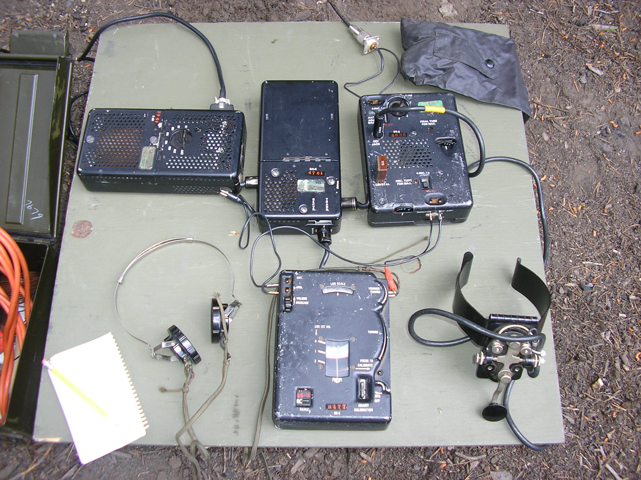
Shown below is an operating set at a favorite mountain location. (“I’m just here fishing…”)
The power supply is on the left, filter/voltage regulator in the center, transmitter on the right and the receiver on the bottom. A 12 volt garden tractor battery and 120 VAC sinewave inverter are located under the table.
My set is plenty worn by apparent heavy operational use, none of the serial numbers match; these are not “shelf queens”. If only they could talk……Actually, they can tell you their story if you pay very close attention. All of my units were built during 1952; the receiver (serial number of 3477) IF cans show a date code of week 48 in 1952.

The RS-6 radio covers 3 MC – 16.5 MC in 2 bands and my transmitter power output is about 8 watts (40 meters) to a simple 100′ wire antenna which is supplied. The RS-6A model covered 4.5 – 22 MC. The transmitter is crystal controlled, it is full break-in and the receiver can be crystal controlled or tuned continuously. The TX note is clean with no noticeable chirp with most crystals; it is a simple, solid design that works well.
The receiver used the HS-301 earplug which I have not yet captured so I use a Trimm Featherweight headset or a crystal earplug instead. The generic high impedance crystal earplug works well. The complete set (less the optional J-45 key) including headphones, cords, crystals and antenna fits in that ammo box.
An interesting variant of the RS-6 was the RS-511. It was a briefcase set that utilized the RT-6 transmitter, RR-6 receiver and a new power supply that included an AC line voltage meter, all being mounted to a single front panel inside a plain briefcase. Simplifies things.
The CIA found that (at least the early) RS-6 sets generated significant “key clicks” that could be heard in nearby Low Frequency European broadcast band receivers. This possibly betraying the nearby operation of a clandestine RS-6 set. These keying transients were generated in the transmitter keying and relay circuits along with other circuit/antenna interactions. Several modifications were discussed; I do not know which one(s) were eventually incorporated.
The RR-6 Receiver:
The receiver is a marvel of miniaturization using the technology available at the time; it is capable of both AM and CW reception. It uses eight “wired-in” pencil tubes (types 5899 and 5718 for all functions) making it very dense – somewhat hard to work on if necessary. It is a super-het with a 455 Kc IF and it incorporates an interesting two-band tuning mechanism/spiral frequency dial.
An interesting feature is the method of obtaining the appx. -4.5 volt DC bias for the detector stage. CR1 in the BFO/Bias Supply circuit rectifies some of the continuously-running BFO signal to produce the required negative grid voltage for the AF Detector stage, V6. It also provides the negative bias for the first RF and 2 IF amplifier stages as an (adjustable) gain control. Clever.

The entire 20 meter CW band from 14.0 to 14.1 Mc is covered by about a 60 degree rotation of the Fine Tuning control. That’s fast… The tuning mechanism has an understandably small amount of dial back lash caused mainly by a small rubber coupling “gear” linking the main tuning gear with the fine tuning wheel. However it is reasonably selective. So you need a steady hand, especially on the higher frequencies…(No mention of the IF band width specification in the manual). It also includes a 500 Kc crystal calibrator.
In addition to the manual tuning, it can be crystal controlled with an FT-243 crystal plugged into the side. That crystal needs to be 455 kc above the operating frequency. The BFO is also tunable or it can be turned “off” for AM voice reception..

Above: The RR-6 Internal layout. The pencil tubes are under those copper clips/heat sinks/shields. The 3 IF transformers are across the bottom. This seems to be about the practical limit in miniaturization using the technology available at the time.
The design includes an RF stage and 2 stages of IF gain. Sensitivity wise, it can clearly hear a CW signal at and below the 1 microvolt level on the 80, 40, 30 and 20 meter bands; it is above the circuit noise. I did not measure the SNR during that check but it is usable nonetheless; not bad, all things considered.
Fun fact: While I was performing this test I happened to tune across a Spanish language numbers (encrypted) station transmitting via AM on 11,462 Kc at around 0530 Zulu. There were many 5 number cipher groups, but then the station switched to numerical addressees callup followed by 24 second digital data streams sent to each apparent addressee.
It shut down transmission at 0550 and turned off the carrier at 0605 Zulu. Someone has gone Hi Tech with these the digital transmissions – no CW cut-numbers groups sent using a One Time Pad….If they only knew that their agent communications was being intercepted by a 1950’s “Spy” radio – the RS-6. HaHa. It could still easily do the job. More to follow.
Is Komrade Lenin still trying to export his “Revolution”?
Here’s a similar coded transmission that I recorded, this time in “cut numbers” Morse Code. Most likely station “M8A” in Cuba. 5800 kc late one night: Click the “Arrow” button.
(Mass-murderer Che “Up Against The Wall!” Guevara isn’t listening anymore, but they do keep trying.)

(Yes, I did hear Commandante Fidel on my old S-120 receiver while I was in high school in the 1960’s…)
I’m not sure if my RR-6 receiver is representative of the performance routinely obtainable, but I feel it is the weak link in the system, at least for “Ham” radio use.
You have to be pretty careful in setting the “Volume” control (actually an RF/IF stage gain control – there is no provision for AGC/AVC). My receiver has limited dynamic range; although plenty sensitive, it is easily overloaded by strong signals. As with the GRC-109 receiver, a useful “after market” amplified speaker helps considerably in setting the receiver gain for optimum performance – and then adjusting the speaker volume so you can hear it.
The receiver is plenty adequate for ham operation under uncrowded band conditions on 80, 40 or 30 meters and will make contacts on 20 but the tuning rate is a really fast up there. I’ve made many contacts out to 200 miles during the day and over 1000 miles on 80/40 at night. The receiver is very sensitive and sounds good on AM with its broad IF passband, but the tuning rate is fast by modern “ham” standards. You wouldn’t try to make THAT comparison, would you?
The receiver just feels “touchy” primarily due to the fast tuning rate – but maybe that is part of the Charm of the set. It does the job as intended but it is no contest receiver – crowded band conditions are not its forte…But it is small, lightweight and concealable – and that drove many design compromises….The more I use it, the more I appreciate what it can do. It’s called Character, something no Ricebox will ever have….
The RT-6 Transmitter:
The transmitter is a 2-tube MOPA design using a 6AG5 crystal oscillator and a 2E26 PA tube. It includes a built-in, swing out CW key which is a bit exposed and fragile but it can also be keyed by an external J-45 knee key (which I prefer in the field) as seen above, or bug. I would consider the built-in key to be an emergency key rather than one to be used for routine transmissions.
“Boss, the designers said they can’t fit a 2E26 in there.” Boss: “Make it fit”.

Most internal components are accessible in this compact space. The yellow object is the replacement T/R relay plugged into a socket. Many parts stuffed in here.
The transmitter includes a simple sidetone function since the receiver is powered off while transmitting. It is designed with a neon lamp relaxation oscillator that is connected directly to the headphones with an external jumper (see Mods below). Simple, effective, odd; I like it!
The transmitter can also be keyed by an external high-speed keyer. CIA FOIA documents mention “MK”, “AS-1” and a “PAMM” (Portable Automatic Morse Machine) as keyers. I think the RS-6 pre-dates the GRA-71 code burst keyer so I am looking for further information on keying equipment and usage. The interface connectors are certainly incompatible. The manual says the transmitter high speed keying jack can follow 60 WPM keying – so that keying source is a mystery.
The “PAMM” keyer sounds like it was a device to permit keying the RT-6 transmitter (at 10-60 WPM) via a paper tape previously prepared by an operator who was not trained in morse code. The CIA was finding it difficult and time consuming to train agents in morse along with other necessary field craft.
The GRA-71 operates at 300 WPM. The RS-6 manual also mentions the possibility of plugging a “Frequency Shift Unit” into the crystal jack. I wonder what that would be used for…Maybe an embassy or clandestine outpost running an encrypted RATT setup at 60 WPM?
The radio is not even remotely water resistant and the interconnects are fragile so it would be marginally useful in the jungle (read: NOT useful). A GRC-109 would be much better choice, albeit much heavier as well. The US Army Special Forces used the GRC-109’s to tie together all the SF “A” Team camps throughout Vietnam on a common CW net and they also used them while on the move. In a jungle “vill” the GRC-109 would have been pretty ideal versus the RS-6 – rugged, forgiving, effective. But that set wouldn’t fit in a briefcase either. For more information on the AN/GRC-109, take a look here:AN/GRC-109 Set
In 1961 the Vietnamese Montagnard “Mountain Scouts” were equipped and trained in the use of the RS-6 radios from their villages. Providing regional communications support proved problematic; the 25 Montagnard villagers trained as radio operators had difficulty mastering the idiosyncrasies of these particular radios once they returned to their home districts.
Not too surprising. I would think a “brevity code” was devised to send basic messages in Morse Code. They often had to rely upon other means of communications. (Reference 26).
There is clear evidence the RS-6’s were widely used by the CIA in the 1950’s – 1960’s elsewhere in southeast Asia, Europe and notably inside the USSR. (References 27, 49 et. al.)
The RS-6 was clearly not designed for tactical military field use but rather as a “brief case” or “Black Base” type radio for the CIA, partisans or similar organizations / missions. (A “spy radio” if you will. It’s such an imprecise term.) Its complete lack of environmental protection is a good indicator.
Also there does not seem to be a standard U.S. military Technical Manual (TM) for this set as there would be for a Standard A issue set. The RS-6 “Instruction Book for Radio Station RS-6” looks very primitive: just sheets stapled together, no document number, date, publisher or author is included (there is an instruction addendum dated 15 May 1953 however).
That said, the technical detail in the Instruction Book is pretty good. Also, I have not found any reference to the RS-6 in any U.S. Technical Manuals or in any Field Manuals as it would be, had it been used by the conventional military. It clearly was (see Jess’s comment below as an example), but that use seems to be limited. However that assessment is based upon limited documentation or history available for this set.
See Peter McCollums notes on the RS-6 radios on W5OR’s excellent site www.militaryradio.com for more details, especially production analysis and insights into possible deployment. He estimates about 10,000 were built. That’s a lot of radios, especially for this type of set.

Above is the complete station ready for extended field Ops at a remote campsite, here driving a coax-fed dipole. Pretty much everything you would need including the PU-181 300 Watt AC generator which is well in excess of the power needs of this little radio. (A standard UGP-12 or XLA115 400 cps AC generator would be more appropriate here.)
For routine use, I prefer the use of the J-45 “knee key” to the installed, swing-out key in the RT-6 transmitter – it is a bit exposed and fragile in the field but certainly lighter and less complex.
The external key, when used, needs to be plugged into the “High Speed Key Jack” only half way unless you modify the key circuit wiring. This was a “burst keyer” accommodation. If you plug an external key all the way in, it shorts out the TR relay into the Transmit position, disabling QSK operation – not what you want during manual keying. An easy mistake for the untrained to make. You ARE trained, aren’t you?
The RT-6 Transmitter Schematic
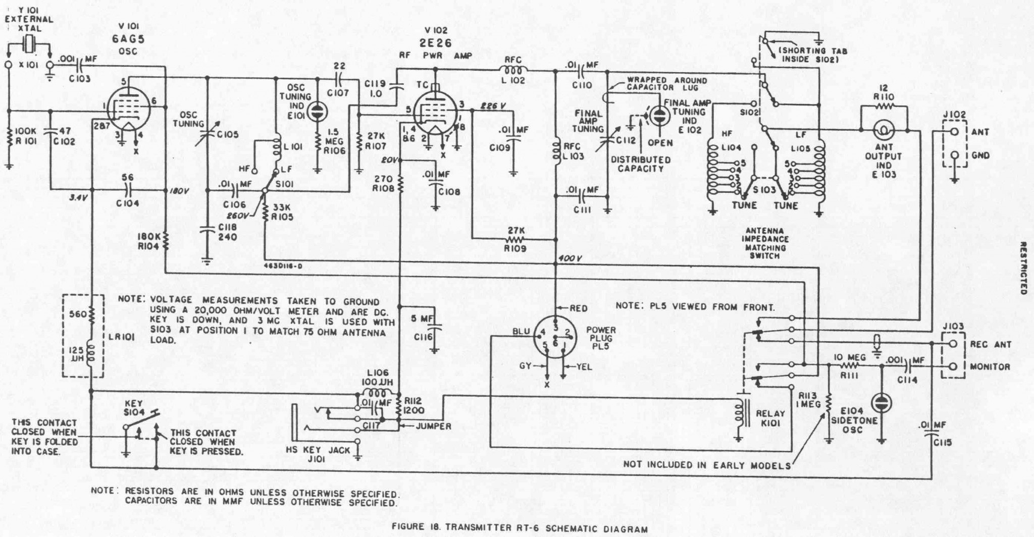
Above: The transmitter schematic. Noting fancy or novel. It would feel right at home in a 1940-50’s Ham Radio magazine or handbook except those would probably have had a link-coupled balanced output or possibly a Pi Network output circuit as the GRC-109 does.
The transmitter operates with crystals in FT-243 holders. For Ham use, fundamental crystals work on 80 or 40 meters or tuned as a doubler or tripler stage for the higher frequencies. It can also be driven by a VFO connected to the crystal socket; below are some experiments with a Direct Digital Synthesizer which works great absent a crystal.
Interconnects much? HiHi

A 20 volt P-P sine wave fed to the crystal jack (via a blocking capacitor) drives the transmitter to full power output on 80 and 40 meters. Ten volts P-P drives it fully on 20 meters. (This DDS Function Generator also drives the RS-1 and GRC-109 transmitters to full output with 1 volt P-P as well.) Not “Mil” but very handy around the home QTH.
By way of comparison, the transmitters in the GRC-109, RS-1 and RS-6 sets use the same PA tube, a 2E26 and all three put out about 10 watts. I have used my GRC-109 to work most US states, from Alaska and Hawaii to Massachusetts and Florida (from California) just using a simple dipole antenna on 7 Mc. I have also worked Aruba and France with the 10 watt GRC-109 from here. These simple 10 watt transmitters and can provide long ranges.
The RS-6 provides reliable comms from zero out to about 500 -1000 miles, more at night, depending of course upon propagation conditions.
If you are working by yourself, or if you need to monitor a frequency for extended periods, the AC generator sure beats cranking the GN-58 for hours. The system makes no provision for powering the receiver from a local HV dry battery (unlike the RS-1/GRC-109) beyond the 6 VDC / lead acid battery setup – if you have a 6 volt car battery and are willing to put up with the vibrator hash. But then again, that is tactically quiet when operating under sound discipline conditions.
The RS-6 in USAF Strategic Air Command service: The RS-6 set was issued (post-circa 1953) as optional mission equipment in a canvas bag for stowage in the bomb bays of the B/RB-47 and B/RB-52 bombers in the 1950’s and 1960’s, depending upon their Op Area. There is also evidence they were carried in the U-2 Recon aircraft (see below).
The set is referenced in a 1959 8th Air Force document (Emergency Rescue Manual 64-1) listing the RS-6 kit and various other survival equipment to be carried in specific aircraft/missions.
See http://k4che.com/RS-6/SAC%20Manual.html an excellent reference site on the availability of the RS-6 aboard those specific SAC USAF aircraft. The idea that after hitting threats “over the pole”, they might not carry enough fuel to make it all the way home.
That RS-6 kit bag includes standard parachute clips that would permit attachment to a parachute harness “D” rings, probably the same ones that the reserve chute attached to. This setup is for a “free jumper” exiting an aircraft or for retrieval from a crash-landed aircraft.

That bag fit the entire set, including the heavy but necessary GN-58 with the “shorty” legs. The bag also included a 20 foot canvas strap with clips at either end that would allow the jumper to detach the kit from the harness during descent and lower it beneath him for a safer landing configuration. Parachutist SOP. Note the off-center lanyard fitting – the heavy GN-58 probably resided in the right hand side for balance. Photo courtesy of Cryptomuseum.com. Check out their great website on the RS-6 and similar gear. http://cryptomuseum.com/spy/rs6/index.htm
Crash land on the ice or tundra at your pre-designated (or random) site, break out the RS-6 and call for a pickup. Battle damaged aircraft might have to try to crash land or have the crew bail out over a pre-designated land location suitable for “E&E” movement or pickup as well. Such a site would be remote, with no roads nearby, but suitable for landing by a C-47 SARP (Strategic Aircrew Rescue Program) aircraft.
Long and short range communications would be essential, of course. A URC-4 VHF/UHF radio would have been the local ground-air set in those days. Its 35 milliwatt transmitter could be heard over 100 miles away by a high altitude aircraft with otherwise line-of-sight to the radio.

Above: The URC-4 with the horizontal dipole antenna configured in the collapsed position for UHF communications on the 243 mc Guard freq. It is likely that the SAC sets were crystalled for a different frequency since 243 mc was a commonly known SAR frequency. Who knows who might also be listening.
On 23 August 1950 the US Air Force had established the 8th Air Rescue Squadron specifically for this aircrew recovery mission. They were equipped with ski-capable SC-47 aircraft that could land on frozen tundra or the polar icecap.
In addition to long range, internal fuel tanks and JATO rockets, these modified C-47’s also carried an ARA-25 UHF directional antenna on the nose to permit the crew to home-in on the beacon signal emitted by the URC-4 survival radios. (I do not know what HF radio SAC aircraft carried prior to the availability of the RS-6 circa 1953.)
Once seen or heard, the SAC crew would switch to voice to coordinate and designate an LZ for subsequent pickup. This of course required the previous use of the RS-6 to radio to contact distant SAC bases to provide their actual coordinates. One-Time Pad crypto procedures were utilized for the Morse Code messages.
A subordinate element of the 8th ARS was the 1875th Aircraft Airways and Communications Squadron. The 1875th was tasked with forward pre-deploying 23 man communications teams with the express mission of monitoring assigned SAC crew RS-6 HF frequencies and then establishing relay communications with them, back to 8th ARS Headquarters. (Reference 80).
K4CHE’s website photo shows a Soviet propaganda photo of Francis Powers’ equipment after his U-2 was shot down on a photo recon mission over the Soviet Union in 1960. Clearly shown is a URC-4 radio with its battery pack; the radio mounted on a tripod with its dual-band ground plane antenna system. The URC-4 was used as a special “Here I am” beacon for rescue operations. Also visible is what clearly looks like RS-6 radio components. [CORRECTION: That photo was apparently taken in 1957 and the equipment shown was not related to the U-2 incident of 1960. It was apparently a Soviet display of captured “spy” equipment.]
Was the RS-6 also carried aboard other long range USAF aircraft to include the U-2? That would make sense to me but I look for primary reference information to confirm or rule-out. Anyone?
Incidentally, below is the last B-47 to ever fly. It was sitting in the desert at China Lake CA weapons test range for use as a photography and radar training target, slowly rotting away. It was then towed 23 miles to a rework area and restored to a point where it could make one last trip in 1986 from China Lake to Castle AFB also in California. Piloted by Major General JD Moore. Cool.
The RS-6 set was also carried aboard Strategic Air Command B-36 bombers along with several URC-4 rescue radios. See Reference 25.

Ejection Seats Nonsense
One persistent rumor is that RS-6’s were somehow “installed” in the ejection seat(s) of the B-47 (and by extrapolation to B-52’s as well) for this purpose. After considerable digging, I have not found any authoritative reference to that specific installation/claim. (Note: Not all B-47 variants even had ejection seats for the 3 man crew due to weight considerations, although most did.)
There was an erroneous quote by the author of an October 1979 Air Classics magazine article (Reference 80) about Operation Armageddon and the assumed installation of RS-6 sets being mounted in the ejection seats (versus simply onboard) of SAC bombers. It may be the source of the rumor further propagated by “circular research” after off-handed comments made later by some Keyboard Kommando’s, thus becoming an Internet Fact. Why a Fairy Tale??
The field-usable SAC RS-6 kit includes the 23 pound GN-58 hand cranked generator and its legs assembly parts: together they are BIG, HEAVY and CLUMSY. Additional weight, volume and complexity is something you don’t want hanging on a cramped ejection seat or somehow sitting in your lap during an ejection.
AC power or 6 volt vehicle batteries would be unobtanium on the ice or tundra. So the hand cranked generator was necessary. So once the crewman ejected, he would quickly become detached from the seat before his chute opened, dooming the ejection seat (and presumed generator, generator seat and radio components) to a free fall to the ice below.
If it somehow survived that, you would then have to go find the fragments at the bottom of an ice crater a mile away from where you landed. Unlikely, in my opinion. Would have never passed a design review. Or even a simple Sanity Check.
Alternatively, I doubt it would have worked as stowed in the pilots ejection seat bottom survival pack either. There is barely enough room (15″ across front, 14″ deep and 2″ thick) in those even for just the radio components, not to mention the compressed life raft, oxygen bottles, water and other survival gear – way too big, heavy and clumsy. (Take a look at any Weber or equivalent ejection seat.)
So only special ejection seats included all the radio components plus this 23 pound cannon ball? No.
Anyone got actual hard evidence on the “ejection seat” story? Proving a negative is difficult; but extensive research has yielded no factual information on the ejection seat “story”.
However, free-jumping out of a bomber, transport or other agent-delivery aircraft with one attached to your parachute harness, why not? (with the below generator legs modification). That was routinely done by Special Forces, agents and other radio-equipped parachutists as part of a combat load.
GN-58 Generator operation: The GN-58 hand cranked generator powering the RS-6 set was also used with the GRC-9 and GRC-109 field sets. It included a big, clumsy folding metal tripod leg/seat assembly. Way too big for a grab-and-go emergency radio bag so an adaption was made presumably by/for SAC. This eliminated the original seat and long “legs”.
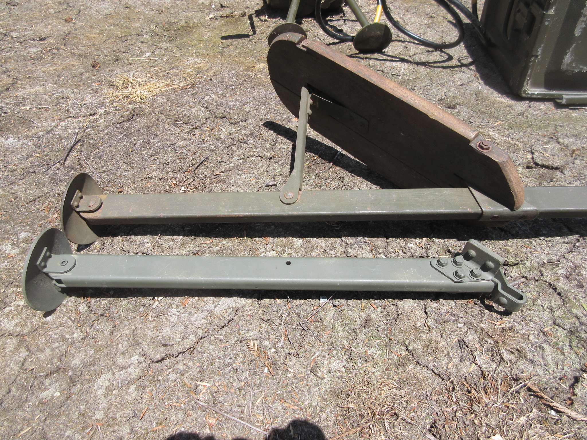
There are a small number of these “shorty” leg sets for the GN-58(*) hand cranked generator in the hands of collectors. The short legs appear to be locally made by the military from parts from the larger LG-2A/3 seat-type mount. The shorty set would also be easier to conceal for an agent moving or working covertly in CIA-type service so this fairly obvious modification may have been more widespread.

Above: The RS-6 set alongside a GN-58A generator illustrating my “shorty” leg set. Much smaller and more compact than the large tripod seat assembly with the LG-2-A seat strut. (Note in the above photo that the CD-1086 cord radio-end connector needs to be replaced with the smaller type to mate with the RA-2 or RA-6 filter accessory. As noted above, that small connector was provided with the set for a DIY “field modification”)
In the short leg configuration it would probably take 2 men just to operate the GN-58 – one to crank and the other to put a heavy boot on the generator to hold it down while cranking. Inefficient but workable. How about the lone Pilot of a crash-landed U-2?
Above: A comparison of the “shorty” and standard LG-2-A seat strut. My working theory is that the shorty struts were locally made from the larger seat and leg assembly. (Possibly modified by SAC but possibly by others; either CIA agent parachutists or those who were otherwise encumbered by carrying the larger seat and legs.) Note the extra hole in the shorty strut – formerly used to attach the seat brace. Pretty good evidence.

Above: Note the hacksaw marks where the original rivets were sawed off and then replaced with common machine screws. Also note that the original LG-2-A was made of steel, the shorty strut is aluminum in this set.
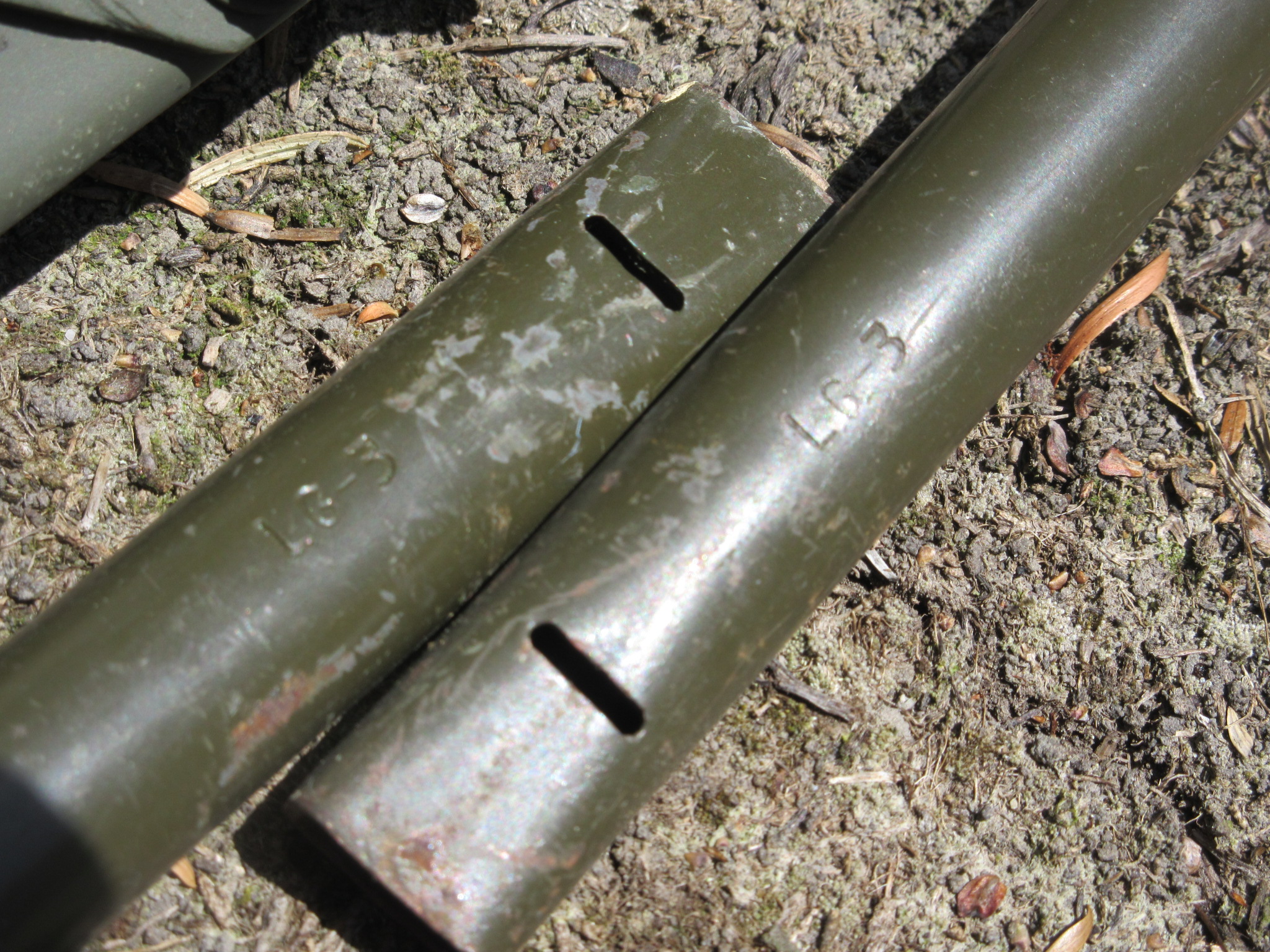
The shorty set also includes a pair of modified LG-3 legs for the rear of the generator. Mine are steel and very likely made from the longer legs of another set. The foot-end of these were cut down.
BT
A friend advised me that if I needed to depend upon it working, I should “bring along a bandolier of 6X4 rectifier tubes”. He sure was right – after a few hours of field operation, the 6X4 failed, its replacement from my spares kit also failed shortly thereafter. Turns out the tube is screaming in poorly-ventilated pain; operating above its maximum ratings for both input voltage and output current. Obvious design weakness with predicable results, just give it some time. (A shelf-queen set would never notice.)
1949-1951 was well before HV silicon diodes were available and space was at a premium for big selenium rectifiers, but come on – this was not workable beyond just brief transmissions. It would never have passed an engineering design review but I am sure the project engineer was also screaming….
Bad things happen when program deliverable pressures approach but there was no device available to perform that task without enlarging the enclosure – apparently deemed unacceptable. I replaced the 6X4 with two 1N4007 silicon diodes and dropping resistors and it now works great. (See Appendix below for details.)
One can operate the set with the power supply voltage selector switch set to the next-higher input voltage (at the expense of performance) to keep from killing the 6X4. No mention of that work-around in the manual. What Operator would think to do that anyway? Anyone else actually used the RS-6 operationally and experience any different outcome?
Also, the filter/regulator unit runs very hot – painful to touch due to the large voltage drop across the regulator tubes’ voltage dropping resistors and the VR tubes themselves. They regulate from +400 VDC down to 85-90 VDC for the lower voltage stages. That heat does no good to the oil filled filter caps either. This radio would not sit on the ice for long, you would need a lanyard to retrieve it from the melt hole. Perhaps that 6X4 bandolier would come in handy.
On the other hand, if you are out on a mission, you can use all that heat to good advantage:

Keeps your coffee hot! Improvise, adapt, overcome…..
The transmit-receive relay is also somewhat fragile as well. Pulled in by the 2E26 cathode idling current (on receive) , it could have used a few more coil turns. In my transmitter, the pull-in force is pretty marginal and a reasonable bump will cause the contacts to let go. This was a design tradeoff regarding cathode voltage, cathode current, keying speed, contact sparking and COTS relay availability. When it works, it works OK, actually pretty well, providing acceptable full break-in using a common antenna, something the GRC-109 is not good at with a common antenna.
The simple TX output network is interesting. The 2E26 drives a parallel resonant tuned tank circuit, via a blocking capacitor, to ground. The tank inductor is tapped by the antenna impedance matching switch; closer to ground for low impedance antennas, higher up towards the plate for high Z antennas. Antenna RF goes through a series lamp as a tuning indicator, works great but carry spares. The manual states it will drive antennas of between 75 and 1200 ohms, depending upon the matching switch setting.
The Instruction Book advises to configure the “Hank” antenna wire as a quarter wave inverted L; up as high as possible. The length equation is provided. This would be a low impedance antenna. The set could also drive a somewhat higher impedance antenna such as an end fed (but shorter than) a full half wave configuration. In that case the output indicator lamp will barely glow when tuning since the output current is correspondingly low.
On the other hand the separate “Description and Operating Instructions” pamphlet advises that the optimum antenna is a 3/4 wavelength wire although a wire as short as 1/4 wavelength is acceptable depending upon circumstances. Both of course recommending a “good ground”.
The PA output network seems to work very well but the harmonic suppression of this circuit would be very poor – not a consideration for its intended use. Simple and effective. (however, a CIA engineering document discusses a possible need for a “low pass filter” for the transmitter output.) I have found the RT-6 loads resonant dipoles, 100 foot and shorter wires (“against” simple radial ground wires), “grounded” barbed wire fences and the rain gutters on the home QTH for stealth operations. Keep it clean on the Ham Bands – use a low-pass filter on the output end.
I run mine in the bush via either a PU-181 gas generator or via a 120 VAC sine wave inverter powered by a small 12 Volt “garden tractor” battery. Cheap square wave inverters generate too much switching hash for the receiver to deal with. The internal 6 volt vibrator supply works but it also generates a lot of switching hash in my set making it marginally useful, overwhelming the receiver. Wonder how that was dealt with operationally…or was that feature reliably ever used. Maybe it’s just my set, the CIA documents do not mention vibrator hash problems.
The inclusion of a wet cell NiCad battery in the Austrian cache indicates its viability.
Out in the Bush:

Above: Running the RS-6 set (on the stump) with a J-38 on CW in camp in the fall. The SCR-284 is listening to the West Coast Military Radio Collectors Net on 3985 Kc. Here using an external J-38 key on the RS-6. I think I was trying to “Break” the AM phone net on CW at the time. Good operators on that net – they listen for weak field sets and CW stations between the T-368’s, BC-610’s and SRT-14’s. Try THAT on an another AM net with Old Buzzards running broadcast transmitters! At a minimum, you’ll run out of kerosene While-U-Wait for a pause…..
Below is the same RS-6 set operational at my campsite. The small 12 volt “garden tractor” battery is seen under the table; the blue sine-wave inverter is nearby to power the station. It will run the radio for several days of operation. The entire station except the battery and inverter fits inside the large-size ammo box on the table, making for a small, compact storage and transport package.
I usually run a coax-fed 80/40 dipole pair for an antenna but sometimes just a random wire in the trees if I am in a hurry. In that case I just throw a long piece of bare wire in the river, weighted down by a rock for a “ground”. In a radio-quiet location such as this, this little radio can hear everything and gets out well.
I tend to like to camp near water which naturally is found in “low spots” (Duh), not generally good for radio. However using NVIS “techniques” (Duh) and careful antenna placement, I can get regional comms out to 500 miles easily with this simple setup even in a river canyon with thousand foot mountains on either side.
This particular transmitter puts out 8.2 watts to a 50 ohm load on 40 meters which is plenty of power for reliable regional comms. It helps if you have a skilled QRP-CW operator on the other end. I’ve even got a few places with “permanent” antennas installed in the trees that I can just hook up to upon arrival. Stealthy construction and placement in a remote spot can come in handy.
Under good propagation conditions the RS-6 can get you several thousand miles on the right frequency at the right time of day with the right antenna. Cross-continent range is not difficult on the 14 MC CW band. If you are working over an unfamiliar path or with different TX and RX equipment or antennas, you can download and use the VOACAP program to help you get in the ballpark in finding the optimum frequency for that path.
Select TX and RX sites, TX power, transmission mode, R and T antennas and run the calculation. The graph will then indicate the optimum transmission times for that situation. Mission planning – It’s pretty good. Provides a graph of circuit probability versus frequency versus UTC time of day.
If you are in routine contact with your buddy over a fixed path and your station and his are a fixed design, you will quickly learn the best freqs and times for reliable comms. No prediction software necessary. If it’s in the “NVIS” parameter set, lower freqs at night, higher during the day, stay about 10 percent below the Critical Frequency fo. If you are a Ham, that’s usually 80 or 60 meters at night, 40 or 30 meters during the day. More or less. It works. More than 1000 miles, go higher and plan skeds for when the sun is between you and your target. More or less.

I modified the AC power Jones plug to bring out chassis ground to a 3 pin wall plug as a safety precaution and to assist in RF grounding the radio when using random wire antennas. Careful – those exposed male Jones pins are HOT with AC before you connect it to the power supply!
Below is another station being set up at yet another campsite, the antennas yet to be rigged. (Vintage Field Day 2006) A good size comparison between the RS-6 and GRC-109 stations. The GRC-109 system with all the accessories and antenna fits in the green transit case under the canteen; the RS-6 fits in the smaller ammo box. (The big green transit case was not designed for the GRC-109 but I use it for that purpose).

The CIA’s RS-6 and RS-1 sets were certainly contemporaries, both specified and designed in the late 1940’s for agent field work. Although they are functionally interchangeable from a users/network perspective, they use different tube technology. The RS-1 using miniature 7 pin tubes, the RS-6 using subminiature “pencil” types similar to those developed for the artillery proximity fuses in WWII. They both use the same transmitter PA tube, the 2E26. But size makes a big difference.
Above: The morning SITREP outgoing from another remote campsite in the Sierras. Our Man on the Ground seems to have a different fist today but he did send the proper security code. So it must be Legit.
One shortcoming the RS-6 has relative to the GRC-109 is its complete lack of weatherization as stated earlier. All 4 units have ventilation or other large holes in their cases which prevents them from being used in a wet/rainy environment outside. It’s imperative to keep it off the ground and best under some kind of cover if there is any chance of rain. A rain fly and simple table did the trick on this Op. If it’s Sun, it’s Fun – If it’s Raining, it’s Training…..
————————————————————————————————
An earlier trip to the mountains; August 2013: Forward Operating Base (FOB) Long Rock.
How’s this poncho for a “roofing filter”?
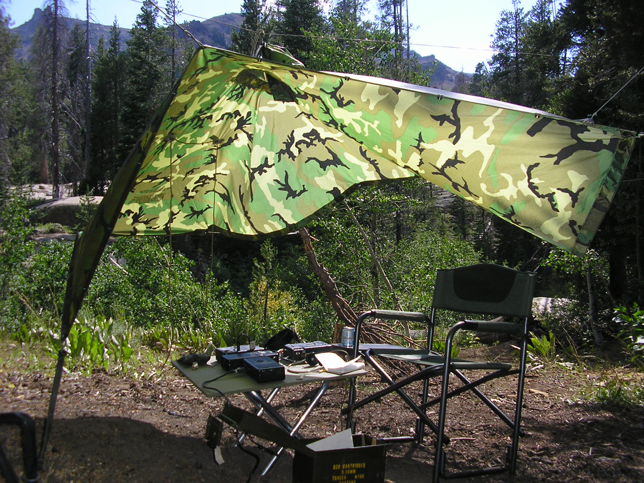
Above: On yet another camping trip to the Sierra Nevada mountains. Here we are getting set up under a poncho hootch with the RS-6. That high-altitude sun can be tough. Here running a 40 meter dipole up about 40 feet on 7050 KC, primarily.
I had a little problem with the set on this trip. There was intermittent arcing someplace on Transmit and that caused lots of receiver noise after switching back to receive at times. There is a component probably in the 450 volt transmitter B+ circuit that is breaking down at this 7500 foot elevation site. Lower air pressure produced lower dielectric strength of air as an insulator. (About a 20 % reduction from sea-level to 7500 feet). That could facilitate arcing…It worked fine at lower elevations, gotta investigate.
Possibly dust between the variable capacitor plates aggravating the situation. The things you learn while actually using this gear as-intended.
Above: The basic setup. Small square of plywood keeps things off the ground. Everything here (except the J-45 Key) fits in the ammo can for transport, storage or caching. This particular set has a lot of miles on it; both mine and from its original operators.

Above: The RS-6 contains a handy set of double-sided, laminated schematic and system setup cards. They store under the spring in the lid of the power supply filter-regulator unit. Very handy for an otherwise inexperienced operator (bring your glasses…). I also included a copy of the TX schematic with some minor modifications I had made. The yellowing paper under the spring is a hand-written note from another RS-6 operator from long ago and far away…..Also seen here is the micro switch I installed in this unit to enable a transmitter “spot” function to get the receiver on-frequency.
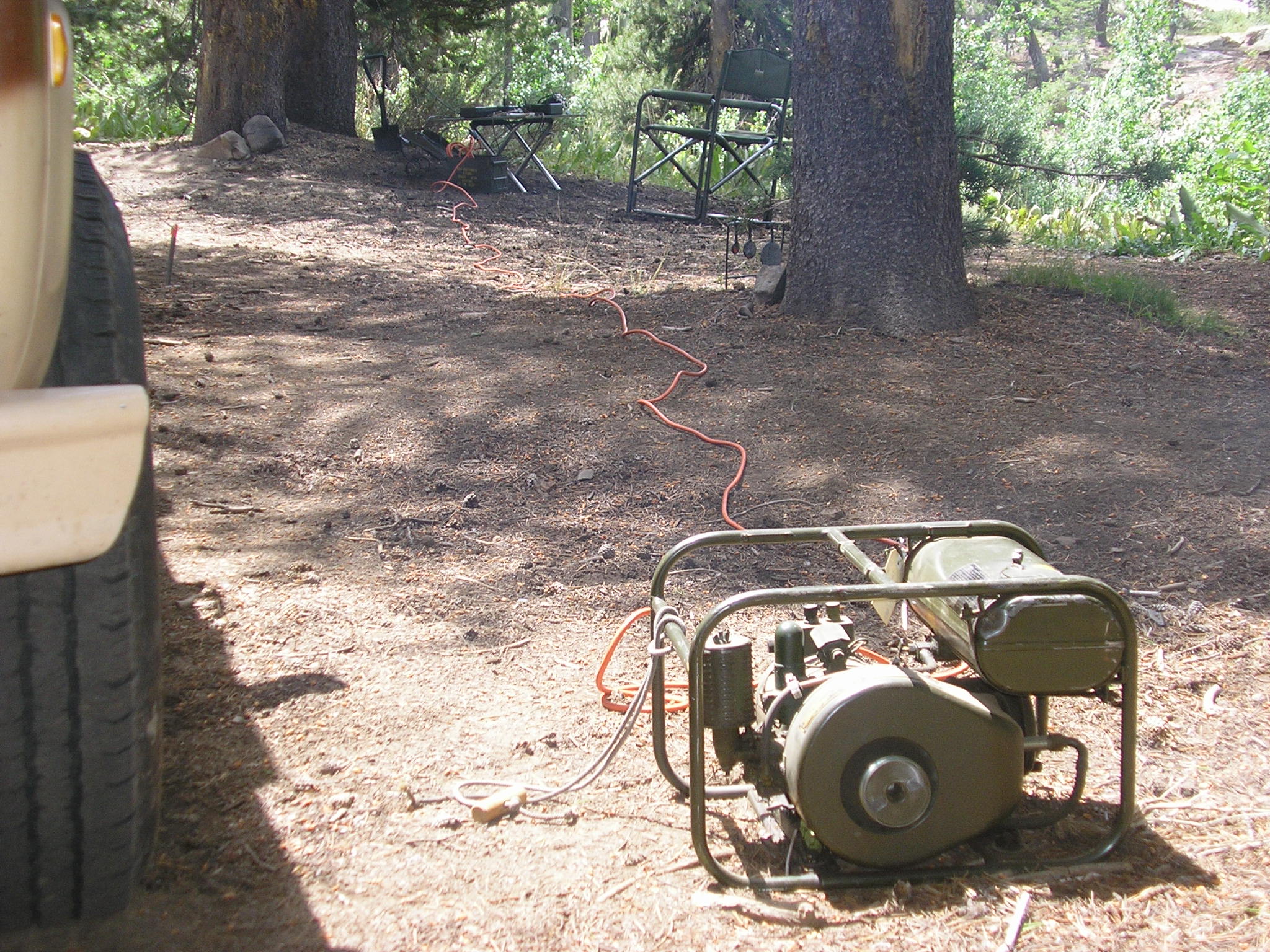
Above: My trusty PU-181 generator powering the RS-6 set. Mosquitoes beware! TM11-943 states that it will run for 7.5 hours at the full 300 watts output on one tank of fuel. When powering even my higher powered military radio gear in the boonies running casual camping operations it will go for over a week on a single tank. Fill it up and go….no need to bring the Jerry can.
Here’s another alternative: The Homelite XLA115 400 cps gas generator.

A 2-stroke, 125 watt, 115 volt, 400 cps generator for the RS-1, RS-6 and GRC-109 sets. Deployed circa 1966. 12 hours per gallon of fuel.
For more information about the antenna kit I use with this and other field radios, take a look here: Portable Field Antenna Kit


Above: Everything needed fits into a standard, large “.50 caliber” ammo can. Or:
Above: If you need to store or cache the entire set, along with a GN-58 hand cranked generator, this is another option. The ubiquitous 20 mm ammo can can hold the entire set, again with the “shorty” generator leg set. Lots of room for additional gear in this completely waterproof package. Indefinite storage if needed. Can you dig it!
Once its design compromises are worked-around, accepted or corrected (apologies to the restoration purists – I feel your pain) it’s a pretty good little field radio. It does the job and is fun to use. All 4 main units, ac power cord, headphones, antenna wire, crystals, instruction cards, spare parts, power adapters, pencil, logbook, one-time pads (ahem) and silica gel bags all fit nicely into a standard .50 cal ammo can for watertight storage, transport or caching. As mentioned earlier, it also has a cool factor 37 db higher than any plastic ricebox ever made by KenYaeIc….
The Cool Factor of the RS-6 goes a long way towards the fun in using this set in the field. If I had to choose between the RS-6 and the GRC-109 – I’d go with the GRC-109 mainly because of its relative ease in setup and “field hardening”.
The RS-6 system is “connections intensive” and uses somewhat fragile power connectors relative to the GRC-109. Also, the RR-6 receiver feels less substantial than the GRC-109’s R-1004, both electrically and especially mechanically. The RT-6 transmitter is pretty solid, works well and is simple but the compromises made in designing the receiver to also be very small makes tuning a bit “fussy”.
It works OK but I prefer the ‘109 receiver for casual operating, especially in the boonies. If I had to carry them any distance – it would be the RS-6 for sure. These two sets were employed for somewhat different purposes: covert/clandestine ops versus more tactical military ops. There is a lot of overlap in capabilities but a direct comparison is somewhat unfair. YMMV!
Meanwhile back at the Safe House…..

X5Z DE B7H GC14 JYPQW SYWGQ HYXLB NQUSD GEUCI SVTTJ GQOZX DXMGV XGMGV XDXGC DSGXX JHXVB ZGNHS JYPQW AR
—————————————————————-
APPENDIX: RS-6 Modification Details
First off, I really don’t like to modify any of these old mil radios – I like to use them as-is as part of the overall “experience”. But this one needed help and is of course reversible if needed; no new holes. Seems a lot of people who have these just fire them up once or twice and then put them away. I use mine a lot and these mods make it much more useful but probably not necessary for occasional “demo” use…
The main issue is the 6X4 rectifier tube operating beyond its limits. A real mystery here; it was clearly the only option available at the time given the packaging constraints. That tube was a bad choice but there are many compromises in this type of equipment to make it small etc. The 6X4 certainly drove the MTBF (Mean Time Between Failures) reliability calculation way down.
I replaced the 6X4 with 2 silicon diodes. Each side consists of a 1N4007 diode in series with a 10 ohm, 1 watt resistor. That assembly just plugs into the 6X4 tube socket.
One diode anode goes into pin 1, its cathode-end resistor goes into pin 7. The other side of the 6X4 replacement diode assembly similarly goes into pin 6 (anode end) and its cathode-end resistor also goes to pin 7, thus making a 2-diode, full wave rectifier. The resistors limit the zero-crossing surge current, protecting the diodes and also reduce the output voltage a bit to simulate the drops in the original 6X4.
A bit of heat-shrink tubing over each assembly holds them in place. Heat is also an issue in the RP6 power supply box and this mod helps a bit by eliminating the need for 6X4 filament power.
I replaced the 5 uf C302 in the RA-6 filter unit with 2 discrete capacitors in series (+ equalizing resistors) rated for 100° C service. It’s HOT in there. C301 was OK, C302 was disconnected but left in place.
I also had to replace the T-R relay eventually. If you have a “hot” 2E26 transmitter tube that draws healthy cathode current, you might be OK with leaving the original relay in place. If it’s not working, you’ll know. Mine barely held the contacts together and it became annoying so I replaced it with a relay that I had, that fit the small space. (12 volt DPDT* Aromet S2EB, P/N AG30236098.) Works great. [*corrected text]
I thought the neon lamp relaxation oscillator generating the CW sidetone was too high pitched – sounded like a mosquito and there are already enough of them around. To lower the tone, I bridged C-114 with a .0047 uF ceramic disc capacitor. Adjust to your liking. More better.
I modified the built-in key system by bending the “stowed contact” switch tab out of the way so the transmitter would NOT be keyed when the key was folded inside. This mod enables successful keying with an external key while the internal key is “stowed” and protected. This disables the burst keying potential but that’s OK; easily returned to normal if needed. Just bend the tab back into position.
I also replaced R110, the 12 ohm “antenna lamp shunt” in the transmitter circuit with a 10 ohm, 2 watt resistor. The original 12 ohm resistor was causing the #49 lamp to fail too often. Too much RF current thru the lamp with low impedance antennas like dipoles. #49’s are hard to find…
A safety mod is to provide for a 3-wire AC power cord since I operate in the bush a lot and was concerned about standing in the mud with 120 VAC floating around from the generator. Remember those Jones power plug pins are males, and HOT when plugged into the AC source…
Simple grounding mod: Replace the unpolarized 2-wire AC line cord that’s wired into PL1 with a standard 3-wire cord. The AC Hot goes to pin 4 and Neutral goes to pin 7. Connect pins 1 and 8 together in the PL1 male line plug, then connect them to the green grounding wire in the new 3-wire line cord keeping the chassis grounded via the polarized plug ground pin. Now the chassis is at AC earth ground. This also helps “RF ground” the radio when using random wire antennas without another ground or ground wire array. Remember to connect the male PL1 to the power supply BEFORE plugging the cord into the AC power outlet!
Another good mod is to add a spotting switch so you can hear the TX in the receiver to know where you are. In the Filter – Regulator module, add a momentary SPST microswitch connected between pins 5 & 6 of TR switch S301 and mount it inside the accessory compartment. When pushed, the PS now powers the RX for spotting purposes when the SEND-RECEIVE switch is in the TRANS position and the key is depressed. Takes 3 hands, but very handy.
CW: It’s like FT8. For Men. ;o)

Many thanks for you site , full of important info , this winter i will start my RS-6 , now i’m missing the power supply , but i will find it . I found too a TAR-224 radio , but nobody can help me to find circuit diagrams or manual . Now this unit work in rx but not in rx . I will be very happy to restore and use this unit radio in my station . Best 73 Gabriele IK6QNE
Hi Gabriele – Yes, the RS-6 is primitive by today’s standards but still fun to use. It has a “mystique” that goes along with it, unmatched by modern gear…Hope you get yours working!
Not familiar with the TAR-224 set; a quick web search reveals it seems to be a more modern version of the GRC-109 with the AM voice capability of the PRC-64. 12 volt power and 20 watts output. A manual apparently dated 1971 and anecdotal use into the 1980’s. An interesting set! Let us know how it works!
Thanks for visiting my website & hope you found it interesting…
73 & Ciao from California !
Tim
Gabriele,
Look on my site, do have the manual for the TAR-224 set, there to download.
Hans PA3ECT
http://pa3ect.eu/TAR224eng.html
Great site! I just acquired a RS-6, but without any crystals. I’m not planning on using the transmitter, but I would like to insert the correct crystal in the socket for display purposes. Can someone provide a close up picture and description of the crystal ?
Gary
Hi Gary –
Well the transmit and receive crystals are type “FT-243” a commonly used WW2 and beyond crystal. Take a look at AF4K.COM he has them for sale and has photo’s of them as well.
Better yet – get your Ham license and get it on the air! Otherwise it’s like a classic ’57 Chevy sitting in your garage and never driven!
Thanks for stopping by the website…
Tim
Find some FT xtal is not difficult , is quiye impossible to find some xtal in HAM band . I found on ebay a lot of smoll HC-series xtal for 3,5 Mhz and 7 Mhz band . I opened the FT xtal and put inside the HC series . The last job is to paint a label with the frequency and the play is done .I think this is the only way to standardize frequencies . best 73 Gabriele IK6QNE
Hi Gabriele –
Yes, FT-243 crystals on Ham frequencies are becoming harder to find. Your method of inserting smaller sized crystals inside the larger FT-243 holders works well – I believe that Brian at AF4K.COM does this routinely. I think he still has some original FT-243 Ham-frequency crystals though. There may be some other suppliers of crystals as well – it’s not yet a “dead” industry! Improvise, Adapt, Overcome…
Thanks & Ciao!
Tim
Great pages, Tim; informative, interesting, and fun reading. The Mongolia photo you show, was
also in a National Geographic book from the 1960s titled i think, “Great Expeditions”. The radio is a Grebe CR-18, 3-tube regen. Now on the RS-6, i found a MARS Bulletin with instructions for
a built in modulator, goes in storage space in ( i think ) the filter unit. I fear that would overstress the power transformer, though.
Hi Hue – Interesting! I took the photo of the Mongolia “field day” display at the NY Natural History Museum about 20 years ago, my apologies to the original photographer ! LOL
Modulating an RS-6…I guess anything is possible – why not? Can you pass that info on – would be interested to see how it was implemented given the layout topology of the basic set…
Thanks for visiting my site!, 73
Tim
Was getting my rs-6 ready for field day again last nite and was playing good as usual for
about 1/2 hour, tuning around. Had not transmitted yet. The center unit (filter) let out
firecracker sort of bang, could see a flash through the small holes, tad of smoke,,,then
all dead??? not much into component repair, is there a place to buy a filter?? Got mine
through the Air Force mars system in 1956. been on a zillion outings. Even took it on
my honeymoon in 1960. Any words of wisdom Tim ???
73, Larry K6AAW
Hi Larry –
On your Honeymoon? You are a brave guy! LOL
The RA-6 filter unit runs very hot with the voltage regulator tubes and their dropping resistors generating lots of heat.. The big filter capacitor in the accessory compartment seems to take a beating – it is oil filled. Rated at 5 microfarads at 600 volts.
Mine failed a long time ago so I replaced its function with some small electrolytic capacitors but I left the original in place (disconnected) for appearances sake.
The sets seem to be around occasionally but I don’t have a source for an RA-6 (or the other units). EBay?? It is also possible that the 6X4 rectifier tube blew up – that might explain the flash and that would certainly kill the operation…. They are badly overstressed in this set/circuit. You might try a replacement – or go with silicon diodes like I did.
Glad you keep it exercised – ARRL field day is a tough environment for this old gear unless you stay outside the bedlam portions of the band.
Hope you can get it fixed and back operational – I really like playing with mine in the boonies…
73, Tim
MUCHAS GRACIAS POR COMPARTIR TODA ESTA INFORMACION,YO SOY RETIRADO DEL EJERCITO MEXICANO DONDE ESTUVE DURANTE 44 AÑOS DE SERVICIO ACTIVO,DURANTE ESE PERIODO ME TOCO VER FUNCIONANDO LOS EQUIPOS DE HF TP-I AN-GRC-9 PRC-74 PATROLPHONE DGT-3 (DE DISEÑO MEXICANO) HAMMARLUND HX 129 HAMMARLUND HX-160 ASICOMO VHF PRC-77 Y DURANTE LAS LARGAS NOCHES EN OPS EN LA SIERRA MADRE OCCIDENTAL DE MEXICO ESCUCHABA A LOS RADIOAFICIONADOS QUE TRASMITIAN EN AM, YO PERTENEZCO AL ARMA DE INFANTERIA PARACAIDISTA Y ACTUALMENTE ACABO DE RECIBIR MI CERTIFICADO DE RADIOAFICIONADO CON LAS LITERALES XEIYCH ¡¡¡¡73 ,AFECTUOSOS ¡¡¡¡
Hola Benjamin- gracias por la nota … Bueno este equipo viejo todavía funciona muy bien incluso pensamos que es obsoleto. Es bastante difícil de romper y que es muy fiable. Como puedes ver me gusta tomar a lo largo de los viajes al campo para que pueda hablar con mis amigos en casa por radio.
Gracias por visitar mi sitio web y gracias por su servicio a México …
73, Tim
I used one of these in the 24th Division LRRP from 1960 through 1963. It would load anything including fence lines and would run off of any power source. I often sat on the folding GN-58 seat, cranked with one hand and used the leg strapped J-38 on the other leg. I also worked a little DX while on some of our field exercises in Southern Germany. Great little rig.
We actually gave the angrc 9 back and kept using the RS6. I remember using the trc77 but more of the RS-6. I had a xtal for 7175 and used it more than a few times in the field between commo checks. I think that solar cycle 19 was in full swing then and propagation was unbelievable. I later became the commo chief and worked out of an AN-GRC 26, now that was raw power with the BC-610.
Jess W6LEN
Hi Jess – That is the first hard evidence I have heard about the RS-6 actually being used tactically in the field as you described. Sure easier to hump around than a GRC-109/RS-1/GRC-9 set for sure. I am sure they were used by many other military field units but written evidence of that seems to have faded into obscurity. I would imagine it did the job for you back then. Thanks for checking in and thanks for your service Soldier!
73, Tim
Hi, great website, infos and pics!
Maybe you already know it, about those cuban encrypted emissions: a brazilian ham, PY4ZBZ, coded a RDFT system software (Redundant Digital File Transfer) and called it DIGTRX making it freely available on his website. One day he casually tuned in a cuban “number station”, the usual female voice reading numbers in spanish, but at the end it switched to digital, sending 5 numbers groups coded with DIGTRX. Freely available ham software used by a government? Interesting… Check PY4ZBZ page with full informations and download here http://www.qsl.net/py4zbz/eni.htm
73 OM
Hi Marco – interesting info on the Cubans using that transmission mode. I guess that once the plaintext is encrypted, the transmission mode could be anything from morse to something like this. Commercial receivers and simple computers at the Out Stations could handle the traffic, record and decrypt offline. It’s also an easy way to make sure everyone’s software is current. Just download it off the web. Why not…
Interesting video at the end!
Even the VOA is transmitting digital program material in MFSK32 and Olivia on occasion.
Thanks for visiting..& 73
Ciao ! Tim
AR
Have one, love it!!
The first oil cap in the filter unit is too close to the hot running voltage drop resistor and will fail and leak oil also. I think best to just remove it and go to choke input; however then the gas regulator tubes will not get enough voltage to fire, so their dropping resistor has to be changed or
paralleled to get back to firing voltage.
Hi Hue – You’re right, those oil filled capacitors take a beating from all that concentrated heat. That RA-6 unit gets REALLY hot. I had to replace mine (C-301 & 302 I think) a long time ago after they leaked. I forget exactly but I found some good mil-spec caps that also had a high operating temperature rating so I installed them. You could modify the design as you suggested but as you point out, that would perturb the power supply voltage and require other changes to accommodate them. That would also reduce the ripple filtering to some extent as well. I did not try that.
There were a lot of engineering compromises in that sets’ design to keep it very small and still meet the RF performance requirements. These caps are examples, the poor 6X4 is another but I don’t know what alternative would have worked given the technology of the day. I’m sure the design engineer was telling everyone what the consequences would be…(been there, done that…HaHa)
Thanks for checking in,, Tim
Hi Tim,
Darn I missed you at Tower Park Camp Delta in Sept. I brought my Bc 654 and RS-6 to get working but I understand you didn”t stay long. I had many questions to ask but the — Guru
wasn’t there. I would like to fire up the RS-6
I do have one question– with my RS-6 can I operate the TX with out the receiver.
I have all units except the receiver– I can’t get the vibrator to work in the RP6 maybe just a on off switch, or it’s just bad. I have repaired the bc654’s vibrator supply and RX works. Any way Keep well and hope to talk soon. Looking for a complete Schematic
Jerry WA6bxv
Hi Jerry – Yes, I was there but just for a few hours on Thursday.
OK on the RS-6. Yes it will work fine without the Receiver but there will be no sidetone as the receiver is part of that circuit. The Transmit/Receive switch is on the RA-6 Accessory Filter unit…
(Hint – if you use the TX with an external key, plug the key only halfway into the jack to the first “click stop”. All the way in is for the burst keyer only..Plugging
in a CW key plug all the way in will disable the TR relay break-in circuitry..)
The RP-6 power supply most likely has a bad vibrator. You can remove the cover (carefully) and then clean the various contacts, they oxidize
readily and are usually in need of cleaning/burnishing. You probably had to do that with your PE-104/BC-654 as well!
It is also possible that the 6X4 rectifier tube is shot, actually likely…
Also remember that the RP-6 is 6 volts DC, not 12!
Good luck – let me know if you want to do a radio check with it.
See you in April,,Tim
Thanks for the informative website.
I ‘ve had/used a RS-6. sold it as being a bit much for field use. My GRC-109 is much more in line with that use.
I had and gave to a friend, a Delco 1500 – fun little rig, again crystal controlled.
Rarele see any of these, the milsurp has just dried up, not a surprise, I supose.
Thanks again,
Don//KL7KN
Hi Don – Agreed! The RS-6 is fun, technologically interesting and historically significant. But a bit much for making lots of contacts during Field Day, beyond just experiencing the set for what it is. The 109 is better suited for more routine field ops for sure..
True: Interesting “surplus” has moved to sources other than the Govt. It’s where we find it now…a lot of it seems to be in the back of closets or buried in garages these days, few on the air..
Thanks for visiting the website! Tim
Tim, I recently purchased an RS-6 set. The power supply needs some work. I have a complete parts list however the description of the neon bulb in the PS is very vague. My PS has the original “Red Tip” bulb but it does not illuminate when AC power is applied, so I assume its bad. Do you have a part number for a present day equivalent?
I really like your idea of replacing the 6X4 with diodes. Have ordered the necessary parts. Larry, KG5OVX
Hi Larry – As we discussed offline I think it may be an NE-2 lamp in the T-2 package style but I’m not sure what the red paint dot signifies. The Instruction Book parts list is vague as you noted. Probably the same lamp in the TX Osc and PA tuning circuit as well.
Just found this, hope this comment finds you well.
You broke my “COOL” meter with this.
Hi Tim,
Excellent article on the RS-6. I had the pleasure of operating one as a novice in 1969 without knowing the background. It belonged to a friend K8HAZ who I have no idea how he came across it. The radio was also widely used by Det. A Berlin, which was a group of SF people there to, as has been reported, engage in “stay behind” missions in the event of a massive Soviet invasion. That would explain the unit found in Austria as this unit worked throughout Europe during their existence. There is actually an RS-6 set that was donated by a former Det. A member to the JFK Museum at Fort Bragg, NC where they have set up a dedicated Det. A exhibit. This unit developed a lot of their own tradecraft in everything from driving to comms.
Steve, WD8NPL
Hi Steve – Thanks for the note – glad you stopped by my website…Sounds like training “stay behind” people is exactly in the SF mission space. The RS-6 would be very good in that application and we know they were deployed for that mission. I need to get out to Ft. Bragg to check out their museum – their website shows it to be really well done. Thanks for the input! Tim