UPDATED 4/28/20
Known Gasoline GENSETS for, or usable with the AN/GRC-109, RS-1 and RS-6 systems:
The UGP-12. 125 Watts, 115 VAC, 400 cps, 2-stroke (manufacturer unknown) as described in the GRC-109 manual as an alternate field power source. At the 2014 MRCG event at San Luis Obispo, Chuck demonstrated his UGP-12 (pictured). It was remarkably quiet and produced little smoke.
The 125 Watt, 115 VAC, 400 cps 2-stroke Homelite Model XLA115/1/400/1P as used by the Army’s 10th Special Forces Group with their GRC-109’s. Photo of a layout for a unit communications team equipment inspection, mid 1970’s.
The PU-181 300 watt 2-stroke generator. Although a component of the AN/PGC-1 Field Teletype system this generator is also useful as a general purpose 240/120 VAC 60 cps power source. I am sure they saw widespread usage running radios, lighting, battery chargers etc. beyond teletype systems.
It is presumed these generators would be powering field radios from a safe house, bunker, forward operating base or as a backup in an HQ someplace – rather than tactical “mudborne” operations.
The UGP-12: Painted white for unknown reasons.. Ice Station Zebra perhaps?

Below: Homelite XLA115 generators along with GRC-109’s, PRC-74’s, PRC-25’s, URC-90’s. An inspection-ready display at an Army Special Forces unit.
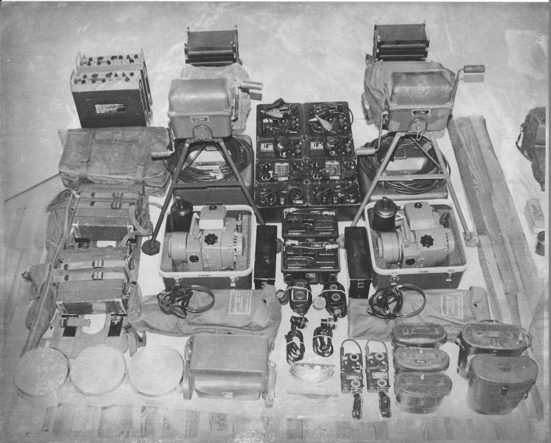
Special Forces comm gear inspection layout photo courtesy of W1OC, 10th Special Forces Group (E).
Also note the GRA-71 Code Burst Keyers, the PRC-74 HF sets and the PRC-25/77’s etc. It seems reasonable that the Homelite generator replaced the UGP-12 later on in time. The Homelite Tech Manual (TM5-6115-405-15) is dated July 1967.
Here’s another look at this little gas powered military generator: The Homelite XLA115/1/400. Approximately 1531 units were delivered to the US Army in 1966-67. Made by Homelite of chain saw fame, the engine was taken directly from the Homelite Super XL chain saw. Clearly designed to meet a specific Army requirement it is an essentially “commercial off-the-shelf” item. It does not carry a usual military PU-xxx designation for generators.

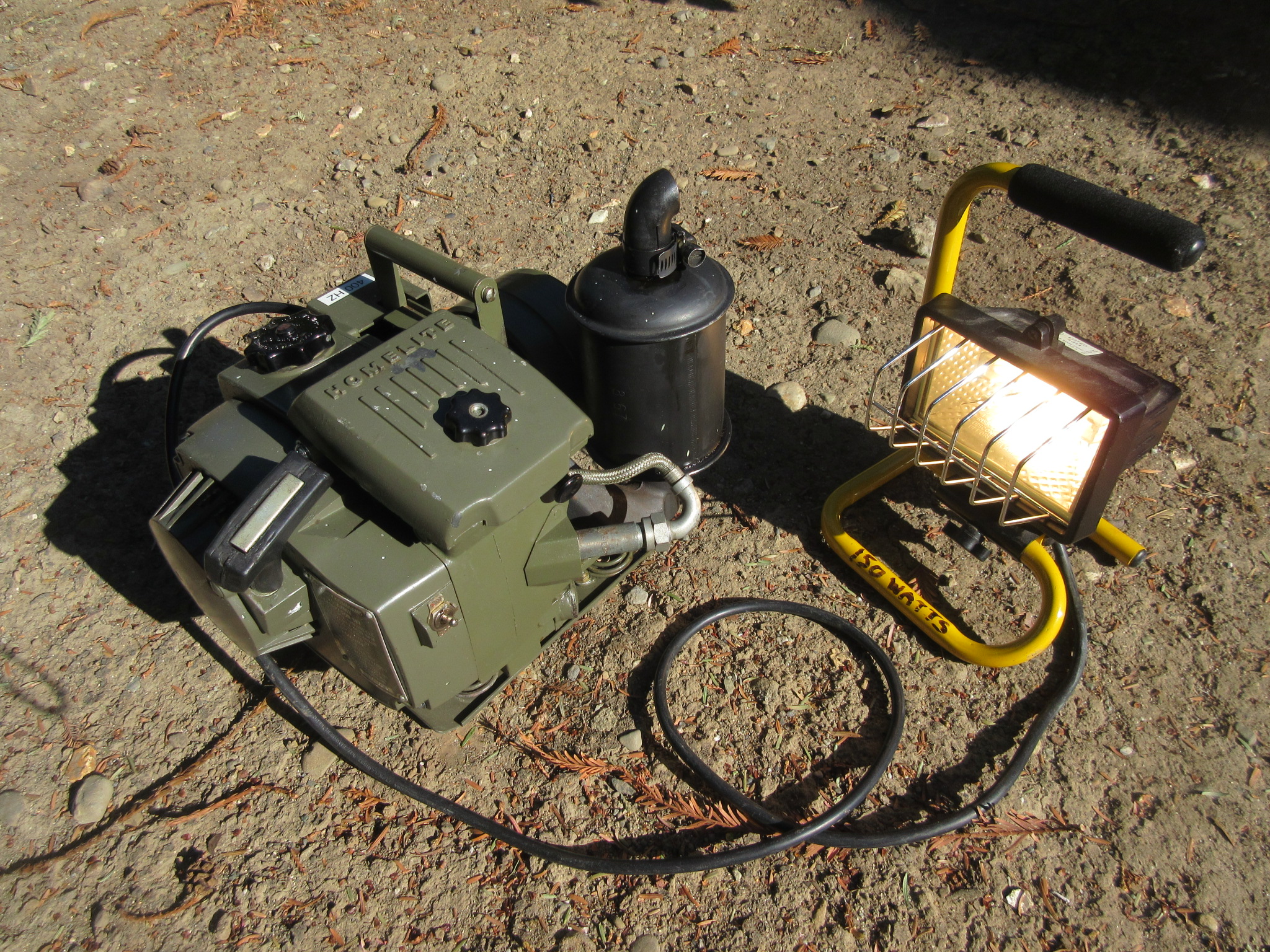
XLA115 generator running from external fuel source
This little guy is rated at 125 watts, 115 VAC at 400 cps, single phase. It was designed to power military radios in the field, notably the AN/GRC-109 and the earlier RS-1 and RS-6 CIA sets that were designed to operate off 115 VAC with AC sources delivering power at between 50 and 400 cps. It will also be a good match for a PRC-47 running in the Low Power setting.
With its two-stroke engine and alternator it will also power incandescent lamps or any other resistive load not to include motors or consumer-grade transformer operated equipment rated for 60 cps power.
This Genset is conservatively rated like most military gear. Here powering a 150 watt shop light for an extended period – no problem. Note the completely shielded ignition system and all metal construction; it radiates no RFI ignition noise into nearby HF receivers. Honda take note!
Homelite XLA115 400 cps generator
It will run at full load for 1.4 hours on its internal fuel tank. It also includes a fuel selector valve that can select an external fuel source such as that 1 gallon fuel can. Very handy, one gallon will run the generator for over 12 hours. The specified lube is SAE 30 weight oil mixed 32:1. I am using synthetic oil in the mix at 40:1 as a better alternative using modern lubrication chemistry.
Just as with its chain saw “father” the engine delivers maximum torque at 4000 rpm. So despite that big muffler it is still fairly noisy, acoustically. But still quieter than the 300 watt PU-181 or PU-162 sets. So operationally, just place it in a 10 gallon-sized hole in the ground outside of your Commo Bunker. Presto!
Then there is the PU-181/PGC-1 Genset that was designed for a field teletype system the AN/PGC-1. This one is also a 2-stroke gasoline powered alternator that delivers 120 VAC, 60 cps. It can be strapped for 240 VAC as an alternative.
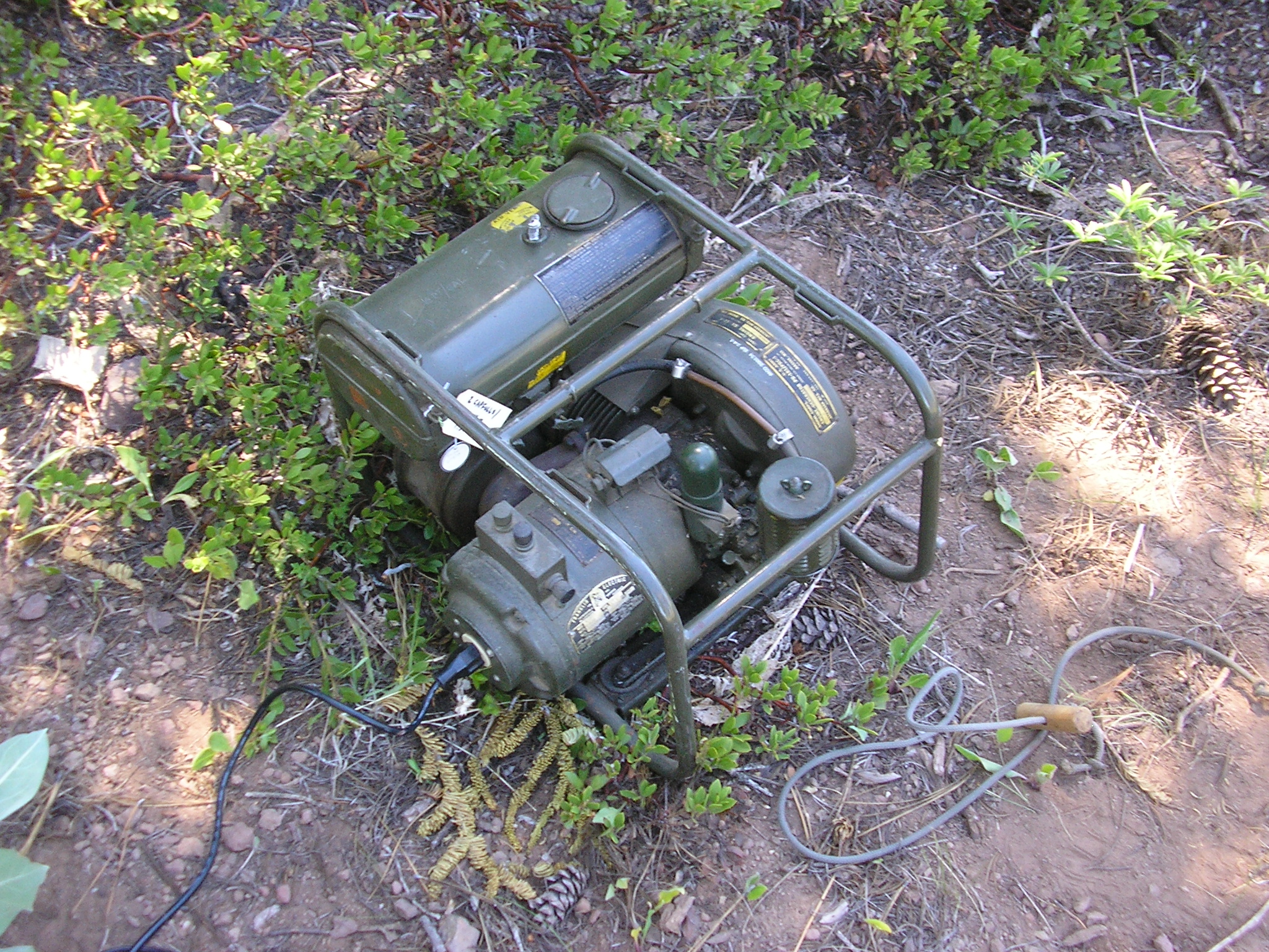
PU-181/PGC-1 Generator in the bush
This little 300 watt Genset was likely used for all sorts of alternate uses besides powering a teletype set. Mine starts reliably even with year-old gas, sips fuel and this one still has the original Korean war era spark plug installed. Here powering a GRC-109 at a campsite. Reliable gear in the field.
With its 60 cps output it will power the GRC-109, RS-1 and RS-6 CIA sets as well as anything else designed for “standard” AC power.
On lubricating the PU-181. The original PU-181 placard specifies 10-weight oil if below 10 degrees F, 30-weight if the temp is above 32 degrees. These days I run 32:1 or 40:1 synthetic lube oil for 2-stroke engines.
There were 2 different sized fuel caps “out there” (doubling as an oil measuring cup). My example has the smaller, 2 inch deep cup. Four of these smaller capfulls of oil per tankful (1 gallon) of raw gasoline. That provides the specified 16:1 ratio of gasoline to lube oil.

PU-181 Fuel/Oil Measuring Cap – Smaller, 2″ size
The above (1951 dated) decal was added to late-production or reworked units as indicated to clarify the issue of 2 different measuring cup sizes fielded. Note the change to use of 10-weight oil at all temperatures.
The story I heard was that the PU-181 and the similar and contemporary generators had either the 2″ or 4″ deep measuring cups (the engines are essentially the same). The PU-181 has a “deep” tank, capable of fitting either a 2″ or 4″ deep cap.
Since these generators were probably both used in Line units at the time, the mechanics would occasionally switch the caps by accident. They are otherwise mechanically interchangeable.
The mixing instructions on the PU-181 tank placard says to mix 1 capfull of oil per quart. That would mean 4 capfulls per tank. (The PU-181 tank holds 1 gallon.)
However, the instructions in PU-181 TM11-943 says to use 2 capfulls per tank. No mention of the tank volume on the placard. Hence the confusion: Which size cap are they referring to?
This resulted in some engines getting too much oil, and others, not enough by a factor of 2. Probably lethal to the ones getting insufficient oil.
So do the math: 16:1 gas to oil.
———————————–
PU-181 Selenium Rectifiers in the Voltage Regulator: The voltage regulator system uses an output winding tap (~1/10 Vout) and a Selenium full wave bridge rectifier to provide a control voltage driving the solenoid-controlled throttle. The Selenium rectifier(s) in mine eventually failed after 69 years of faithful service. That caused the engine to run at full speed, Vout > 150 VAC.

PU-181 Selenium Rectifier
Some white corrosion-looking powder appeared in the diode assembly:
Some fact-finding experiments are in order:

PU-181 Selenium Rectifier Replacement
I replaced the Selenium stack with 4 Motorola MR820 silicon diodes rated at 5 Amps; the common 1N400X diodes have adequate Prv rating but insufficient current rating headroom. The solenoid draws about 1 amp; polarity is unimportant. I included a series resistor to substitute for the higher forward voltage drop of the original part. With these diodes, a series resistance of between 3 and 4 ohms driving the throttle solenoid is about right.
As designed, the engine starts and then accelerates with full throttle until the output voltage rises to the point that the diode bridge sends enough current to the throttle solenoid to close the butterfly to reduce the RPM’s. Equilibrium is reached when the generator output voltage reaches about 120 VAC (Adjustable) under load, and the throttle then adjusts the engine RPM’s to maintain this output voltage.
The 120 VAC “set” voltage is accomplished by turning the brass solenoid spring nut (shown below); CW increases speed, CCW decreases speed (and resulting output voltage).
This is tricky to set as you want the engine to run at maximum torque; 1.25 HP @ 3600 RPM and the desired 120 VAC at the same time. This may require adjusting the position of the solenoid lever on the throttle butterfly shaft to meet these criteria. This required some experimenting with the new (lower voltage drop) silicon diodes and that series resistor to get the system into equilibrium. Solenoid current was about 900 mA with this configuration.
A minibox saves the day. I installed a 3.9 ohm, 10 watt wire wound resistor between the diode bridge and in series with the throttle solenoid coil. Very conservatively rated parts here.
I use this generator pretty routinely in the field to power my military radio gear. So functionality is more important to me than “the original look” if compromises must be made. Looks like Hell, works like a Charm.

Selenium rectifier replacement parts
Make sure everything is tied down tight in this high-vibration environment. Nylon cable lacing twine, a few blobs of silicon RTV to reduce any possible movement.

PU-181 Silicon Rectifier Housing
Install the cover, do a shakedown test, back in business.
The little Homelite, at 400hz 1phase, would be right at home powering the AN/Prc-47, it would seem to me.
Miss those days on radio watch. Bench mounted Trc-75’s, RT-524’s,r-442’s, tsc-15’s,ie.
USMC 68-88.
Made a field expeadiant antenna from 8 aluminum cammo poles and field wire.
What I thought was a “birdcage” turned out to be a 32ft conical mono-pole. Patterned it after a picture of battleship New Jersey’s hf antenna on the bow. No top hat. Tied into a Mrc-83/Trc-75 with homemade 400 ohm ladder line made from wd-1/tt and popcicle sticks.
Tuned in 3 seconds. Contacted Iwokuni,elmendorf,Clark,hickam airbases on 100 watts.
Put a florescent tube on pole to warn everyone away, was running Ratts to Okinawa.
Really enjoyed your blogs and web pages. 73’s
BTW, just finished gathering my Angry-9 and getting ready to recap it.
Patterning mine as a ANGRC-9X, as I have a DY-105.
Hi Russell – Thanks for the note – very interesting….Yes the XLA115 certainly powers the PRC-47 on Low Power. I would think many were also used for that system in Vietnam, a good combination. Fluorescent lamp on the antenna pole – great idea! I bet that drew some strange looks!
Thanks for checking in & thanks for your service…
S/F, Tim