
And other simple DIY Antenna Contraptions
“If it’s stupid – but works – it isn’t stupid”
Murphy’s Laws of Combat
UPDATED 11/6/2023
A good field expedient antenna must first start with a good antenna design. Or at least you should be willing to accept (and understand the reasons for) potentially marginal performance. The expedient part is based upon availability of materials but you have to start with a good design.
Some of the following field antenna designs are suitable for long-term installations at a remote location/favorite campsite for use when you arrive for example. Very expedient in those situations. For some more thoughts on stealthy antennas, take a look here.
The standard DIY references for military and civilian antennas is the ARRL Antenna Book (Reference 45). The RSGB series and the U.S. Marine Corps Field Antenna Handbook MCRP 6-22D (Reference 88) are also excellent.
Full of tried and proven antennas for a range of frequencies of interest from LF, HF, VHF, UHF and beyond. The designs are based upon solid engineering but backed up by solid measurements and practical, proven performance in a real environment. Start there if you are new to this stuff! Read it a few hundred times. Learn, Practice, Evaluate, Experiment, Communicate!
Run what you brung. Improvise, adapt, overcome.

Field expedient antenna wire end insulator – You get the idea.

Above: I needed a quickie quarter-wave ground plane antenna cut for the UHF bands but made with available parts laying around. An SO-239 chassis connector with coat hanger radiating element and ground radials soldered as shown. The RG-8/U 50 ohm coax connects to it via an PL-259 connector, a vent pipe and some tape makes it happen. I can receive UHF SATCOM signals with this, especially the ones lower on my horizon. Gain is good if you can get it, simple can work. Nothing original here.
Happy Halloween!

For small quarter wave VHF/UHF ground plane antennas, working in centimeters is convenient:
L=7120/F
Vertical element approximate Length (in centimeters) = 7120/F(mc).
(Or L=2808/F when working in inches)
Make the radials about 5% longer, sloping downward about 45 degrees makes the feedpoint pretty close to 50 ohms.
Coat hanger wire works well in a pinch, it it usually lacquer or paint coated so it will not rust in the near-term. Another good material is TIG welding rod. “Harbor Fright” sells 3/32″ TIG rods, type ER4043. About $1.00 each, they fit inside the female contact of an SO-239 coax connector. They work well. Below are some 1/8″ TIG rods for a bigger connector diameter installation.

These rods come in 30″ lengths, probably a lifetime supply for $9.00
The basic HF dipole antenna: The overall length, end-to-end, of a halfwave dipole antenna:
L = 143/F
Where L = the length in meters and F = the operating frequency in MHz.
(Or L=468/F where L is now in feet.)
Take a sharpie pen and write those equations inside your helmet. Also, write down the span of your arms for measuring antenna wires; for HF, it’s close enough. While you are at it, also write down the number of paces you take to cover 100 meters and the local magnetic variation of your current Op Area.
——————————————————————————————————————————–
The Antenna Engineers Axiom:
“You can have High Gain, High Bandwidth or Small Size. Pick any TWO”
“Choose wisely” The Old Knight
For those operating frequency-agile HF ALE systems or SINCGARS frequency hopper radios, consider the above.
Ever wonder why those commercial “Mil” folded dipole wire antennas have a big RF resistor near the feedpoint? Or wonder why the OE-254 antenna is such a big clumsy beast? (while trying to fabricate a field expedient clone that will work?) The OE-254 has a little gain over a dipole but more than a simple whip. It has high bandwidth to accommodate the wide (30-88 MHz) freq hopping limits of the SINCGARS radios. So it’s BIG for a reason.
It produces a little gain, over a large bandwidth but it is NOT small.

Speaking of water bottles, see that innocuous water bottle up on the roof? Look closely at the center ridge tile – see the wire? I used the plastic bottle (with a little water in it) to sling and insulate one end of a dipole antenna up on the roof of the NCO Club at Camp San Luis Obispo, CA. On 7050 KC I used it to work station K6KPH over 200 miles north of here with a GRC-109 running 10 watts on this end. No one the wiser. The ubiquitous plastic water bottle makes a handy antenna insulator or lanyard heaving weight with the addition of a little sand or water.
DIPOLE CENTER INSULATOR: Although maybe not technically a “field expedient”, below is a photo of a simple DIY assembly to serve as a GRA-4 dipole center insulator/connector. AKA a “Cobra Head” in Army parlance, useful at a more fixed position installation. This one can be made with a little pre-planning. Made from simple hardware store parts, it can be used for an ends-supported dipole, a center-supported dipole a Vee Beam or an inverted Vee antenna.
It can also be self supporting just by sliding the “tail” into an standard AB-85/GRA-4 antenna mast section – it’s a perfect fit. In this configuration it can be set up as a “Near Vertical Incidence Skywave” (NVIS) antenna system with crossed dipoles for both 80 and 40 meters if kept “low” and the proper freq is selected for the range requirement and time of day. Or any other freqs you may want to design it for. (If you are after 1000+ Km range via the ionosphere, place it about one half wavelength high.)
I have had good results when configured for “regional ranges” with a 20 foot AB-85 mast supporting this insulator with the 4 legs of 80/40 meter dipoles providing support in an inverted Vee configuration. The 80 and 40 “Hot” legs are connected to the Red post, the other 2 legs to the Black post – this puts the dipoles electrically in parallel. This is electrically equivalent and works just as well as the AS-2259 “NVIS” antenna system.

As you can see above, the insulator is made from 3/4 inch PVC pipe parts: a 4-way “Cross”, 3 end-caps, 4 short pipe sections, a 3-way Tee and a 3/4 to 1/2 inch adapter to provide support to the SO-239 connector. It includes a longer pipe section at the “bottom” to fit inside the AB-85 mast end.
All joints are glued with the exception of bottom pipe – it is slip-fit to ease internal assembly and it carries no tension load. The Cross has the 4 short pipe sections attached: They go to the 3 end-caps and the bottom one goes to the 3-way TEE. The longer pipe section goes out of the “bottom” of the TEE for free standing operation.
Each end cap has a 1/4-20 stainless steel eye bolt and a pair of suitable washers under the assembly nuts to distribute the stress load to the end caps. The “top” eyebolt is also unconnected electrically – it is just a tie point for hanging. Each dipole leg eyebolt just provides a mechanical connection; they are not electrically connected to anything either. A shot of OD spray paint keeps it inconspicuous and protects the PVC from the sun’s UV rays if it needs to deployed for longer periods.

Once secured to the eyebolts, the dipole legs actually connect to the red and black terminal posts, front and rear, as shown. Each dipole quarter wavelength element leg from this center insulator assembly out to the end of the wire is of course half of the overall length from the above equation.
The posts are wired to the SO-239 which is screwed to the 3-way TEE via the adapter (drill and tap holes for 4-40 machine screws into the PVC 3/4 to 1/2 inch adapter). The Red and Black posts are connected internally to the coax center and shield respectively.
That coax is then wound around a large ferrite core to form a current choke to help keep the radiation symmetrical – minimizes feedline radiation. (The choke or a balun is really not necessary but they are a “good engineering practice”. As a practical matter a boonie dipole will work fine without them and the distant station will not notice any difference.) A short RG-58 C/U jumper to a PL-259/Barrel completes the electrical connection the the radio system.
This thing is easier to build than to describe; it will actually take a pretty good beating in the boonies.. If anyone else came up with the same idea I apologize. After spending five minutes in a hardware store looking at PVC fittings, this thing practically designed itself…

Above: See the dipole center insulator cross above the apex of the parachute? The PVC fixture is slid into the AB-85 mast that also supports the T-10R parachute sun shade about 20 feet up. The wire dipole elements were just laying along the top of the 10 foot bushes. Worked great for regional NVIS and even cross-country contacts.
With a pair of dipole legs cut for 80 and 40 meters (or any of your other favorite 2 low frequency bands) and fed with coax it will be essentially identical to an AS-2259 antenna at 1% of the cost. It will deliver the same “God-Like” performance some ascribe to the simple AS-2259. I find that when the two frequencies are harmonically-related like 80/40 meters, no “tuner” is needed in a “50 ohm” system.
The AS-2259 is a good mechanical design (I couldn’t afford one!) but is basically just 2 dipoles at 90 degrees to each other, fed in parallel via a 15 foot transmission-line support mast. (The RF loss in a 15 foot coax-mast or cable are essentially negligible at HF frequencies.)
Also note that the dipole legs of the stock AS-2259 are not intended to resonate at any particular frequency. The impedance they present (and as further transformed by the 15′ transmission line) are intended to produce a capacitive load over the 2-12 mc operating range. The PRC-47 is designed to drive a capacitive load.
There is also nothing “magic” about 15′ – that was probably selected as a compromise to make the system small, light, easily transported and erectable by 1 man. Higher would certainly produce better gain. A bamboo pole or PVC pipe with coax or WD-1/T commo wire feed will work just as well – the guy on the receiving end could not tell the difference.
You could also build it without the current choke or the SO-239 connector or the AB-85 adapter pipe. Just use either a 4-way cross or a Tee and let the coax hang down.
Here’s another dipole center insulator built with scrap plastic and connectors: Connect the coax connector center pin to one screw terminal, the other goes to the chassis connector “ground”. Cheap, simple, lightweight, obvious.

Above: Dipole center insulator with SO-239 Coax Connector

Above: A similar insulator made in a hurry from scrap plexiglass and a couple of screw terminals. (Nothing becomes more permanent than a temporary fix…This one has a lot of miles on it) Ordinary machine screws and nuts would obviously work fine as well. This one is already connected to the coax transmission line with Zip ties, the radio end has pins for connecting to the GRC-9, GRC-109 or similar radio antenna terminals. Scrap 50 (or 75) ohm coax.
Just tie the wire elements into the holes in the plexiglass, connect to terminals, hoist up – GO! Again, maybe not something you can whip up with a coconut and kelp but a little time with a saw, drill and scrap pile before you deploy will save you a lot of time later…. A shot of O.D. spray paint makes it (and the coax) somewhat stealthy when powering up an old oak tree in contested territory:

Here’s one you can buy:

Above: Another off-the-shelf expedient, a Pomona 1296 shown here, or the preferred Pomona 1452 (female) BNC/Banana terminal adapter. The female Pomona 1452 (NSN 6625-00-102-5652) is preferred for a dipole fed by RG-58/U coax with an existing BNC male connector already attached. Otherwise you will need a “BNC double barrel” adapter as shown above.
This can work well and is simple and small. However the coaxial cable can pull out of the BNC cable connector if the feedline is too long/heavy. The feedline may need some strain relief at the connector for long runs back to the radio. Some 550 cord and a Prusik Knot are your friends…
Directional wire antennas via terminated end points:
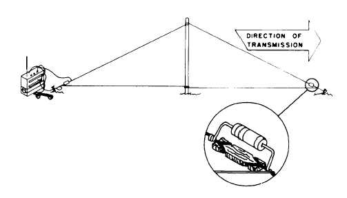
You can rig a dipole as a directional “Vee” antenna from a single support with the desired direction of transmission/reception along the mid line of the Vee angle. If the wire legs ends are un-terminated (insulated from ground), the antenna will be bi-directional along the mid line azimuth.
It will be somewhat more uni-directional away from the mast if the far ends are terminated to a good RF ground via a non inductive resistor equal to the characteristic impedance of the antenna itself: about 300 ohms each. Each resistor should be rated to handle at least half of the transmitter output power. Take a (close) look about how NOT to do this:

Above: From US Army Field Manual FM7-92. Sadly, it also appears in several other related US Army Field Manuals including FM 7-93, FM23-10 and ATP 6-02.53 (redrawn with the same errors).
It even appears in communications-specific Field Manuals in the 24 series including FM 24-18 Tactical Single Channel Radio Communication Techniques. It also appears in several knock-off publications and is widely seen in web searches and quoted elsewhere. Anyone notice the gross design errors in both drawings as shown above? Not even close.
The resistors need to be at the ground end of the Vee or single-slant wires – and connected directly to a good RF ground, certainly not in series with an insulator or “mid-wire” as shown.
Also, in the lower drawing with its mid-line, insulated resistor, what’s the twisted pair “transmission line” connected to? A single wire at the top of the mast ? Shorted together? Wrong again. These are not just sketch mistakes – they are conceptual errors.

Even the otherwise excellent Marine Corps Antenna Handbook shows the Vee antenna termination resistors in the middle of the radiating wires although in a different drawing that further propagates the mistake. (Reference 88). The Troops certainly deserve better resources.
Really poor quality control on that widely referenced image. Beware. The manuals don’t always get it right.
If you are going to be building field expedient terminated (directional) antenna systems refer to the ECAC Field Antenna Handbook published in 1984 for the Joint Chiefs of Staff, Reference 90. It has design and performance information for most common wire antennas without the many errors in the above mentioned Field Manuals and their clones.
Another good reference, although very abbreviated, is Special Forces Operational Techniques, FM 31-20. (Reference 91.) The terminated expedient antennas are drawn properly and clearly illustrated.
Obtaining non-inductive, high powered termination resistors can be a problem. They should be around 300 ohms for each end of the Vee configuration, about 600 ohms for terminating a single wire or half-rhombic. Close enough for a ship this size. DO NOT use widely available, conventional wire-wound resistors – their inherent inductance defeats the purpose of the termination.
The Federal Supply System is not much practical help* although Palomar Engineers is now selling an assembly. Otherwise to get a 300/600 ohm non -inductive resistor with adequate power dissipation you have to improvise with series-parallel networks made from discrete carbon composition or thick-film type parts.
An Old School field expedient termination resistor often quoted is to use the carbon center core rod from an old BA-30 (D Cell) battery of the Carbon-Zinc variety. These can be around 700-1000 ohms and can handle maybe 5-10 watts and will work at low power. However C-Z batteries are mainly obsolete but sometimes found in “Dollar Stores” as cheap Heavy Duty, Extra Heavy Duty or Super Heavy Duty imported types. Modern “alkaline” batteries use a different chemistry so no carbon rod inside. Mentioned here for the sake of completeness.
*The Federal Supply System carries 106 ohm, 100 watt, non-inductive carbon composition resistors. FSN 5905-00-764-5573. However these are rather large at 1″ diameter, 12″ long. A suitable 600/300 ohm termination resistance would require 6/3 of these parts wired in series. It is close enough and will work but somewhat impractical for a temporary or expedient field antenna system.
Here’s how you can make a reasonably effective field expedient termination resistor from available materials likely to be around. Remove the paint from the aluminum guy stake; maybe add a connection bolt as in this “deluxe” modification that I frequently use:

A water bottle antenna termination resistor using a salt solution.

Dissolve a half-pinch of salt in 500 ml of bottled water. Split the field wire into 2 separate conductors, strip about 6″ of insulation from the ends of each conductor. Immerse the conductors in the salt water, keep them as far apart as you can (don’t let them touch). Connect one resulting lead to the end of the antenna wire, the other to the ground stake.
Shown below, the antenna wire “end insulator” in this illustration is an old style plastic MRE spoon anchored to the ground stake with a piece of cord. The ground stake is in a small hole filled with water and any excess salt to keep the soil moist and conductive. Keep it wet.
The “bottle resistor” is across the insulator not in series with it. This setup will make your vertical half-rhombic antenna more unidirectional away from the feed point/radio.

As described this will be close enough to 600 ohms to be effective. Taking advantage of the high Specific Heat of water, 10 watts of continuous RF power will raise the temperature of 500 ml of salted water (in an insulated container) less than 36 degrees F in one hour. Scale accordingly, but fine for nearly any temporary field-expedient installation lacking “real” parts.
Below is a drawing of a vertical half-rhombic as might be used with a point-to-point VHF FM set, or even a long range HF set if many wavelengths long. This drawing shows the correct placement of the termination resistor and it includes a ground return wire back to the transmitter chassis (in lieu of, or in addition to a ground stake) which also helps.
On the “low” VHF bands with something like a PRC-25/77/119 about 150′ (or roughly 5 wavelengths) of wire for the antenna and supported (and insulated from the support) in the middle at about 30′ works well. The terminated vertical half-rhombic antenna is fairly broadband.
Need something REALLY simple? A field expedient dipole with field wire.

Above: On the go? Only have some WD-1A/TT infantry field commo “slash” wire, speaker wire or Zip cord for your dipole? What could be simpler? Just unzip the leg lengths you want, tie an overhand knot to keep the feed line portion from further unzipping, hang it up.
No center insulator available or needed for low power operation? The wire insulation itself does the job.
Assuming the feed point looks like, say, 72 ohms and you are feeding it from a 20 watt transmitter, the voltage here between the legs = 38 volts RMS. No problem for this insulation. At 100 watts it is only 85 volts, again no problem. WD-1A/TT wire insulation is rated at 1000 volts RMS (MIL-DTL-49104C) per conductor, so you are not going to arc it over when operating the antenna at its resonant frequency. You can also use lamp “zip cord”, speaker wire, demo wire etc.
Or rig it vertically for VHF ops with other vertically polarized VHF stations in your Net. In either case, run the feed line away from the antenna at 90 degrees for at least a quarter wave if you can (for a more “textbook” omnidirectional radiation pattern).
Or rig a field expedient wire dipole with no feedline at all:

Above: Another expedient antenna setup. Here the two 67′ dipole antenna legs are connected directly to the TRC-77 HF CW set, no transmission line at all. One wire leg to the Antenna Post, the other to the Ground Post. The wires exit the window and then off to the trees in opposite directions. Quick and dirty 3.5 mc antenna, works just fine for “armchair copy” at the Safe House. Or, at a field location:
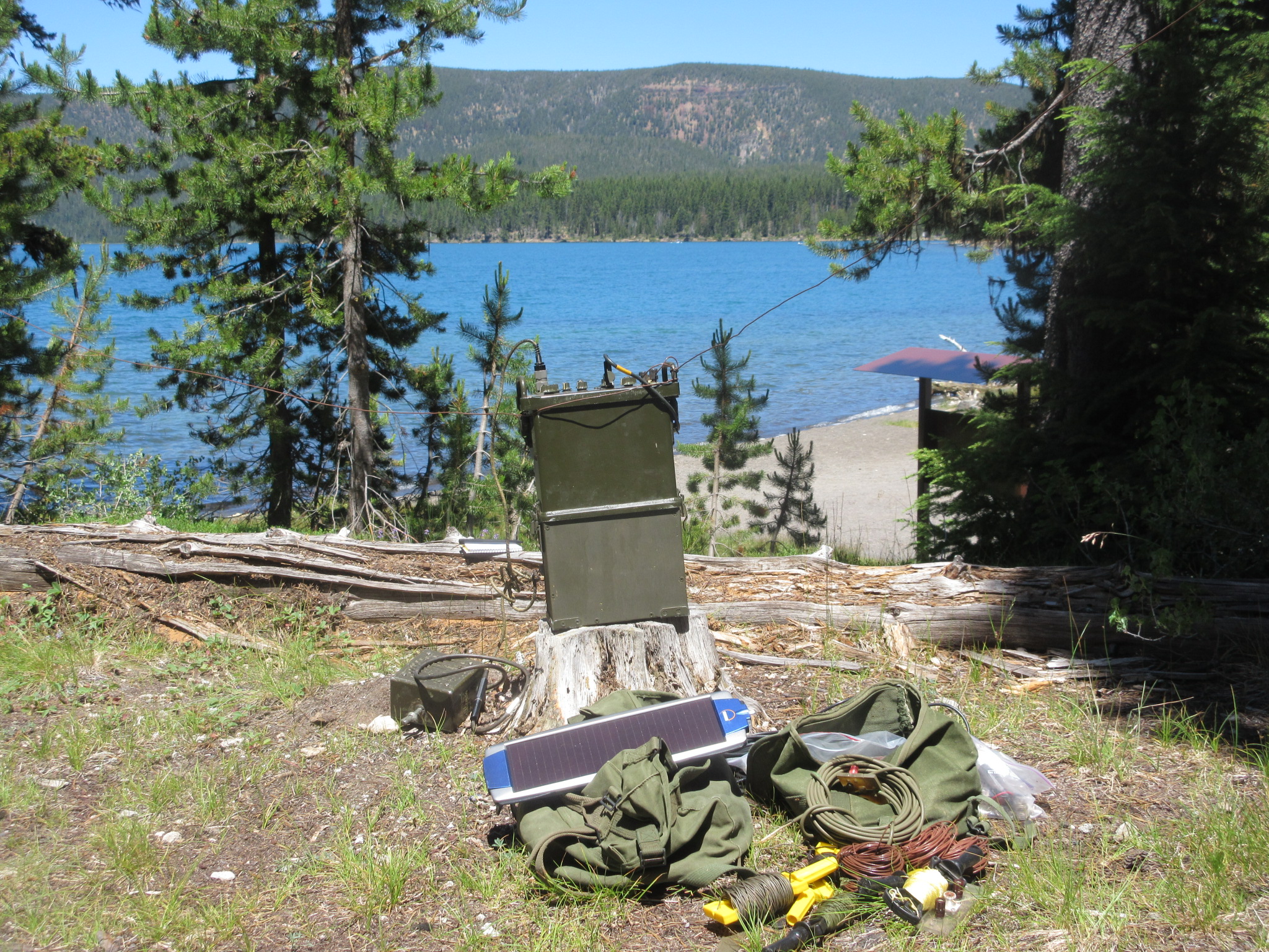
Above: You brought your complete field antenna kit but you just arrived at these coord’s – and your comm window starts in 8 minutes. No time to rig a coax-fed dipole. So rig a Hasty Dipole; just the two dipole legs connected directly to the radio Antenna and Ground terminals, no transmission line.
With resonant quarter wave length wires off into the trees, it tunes to full power with this 10 watt TRC-77 at a lakeside coastwatcher site. Here after working a mobile outside Glacier National Park in Montana on CW, 450 + miles away on 7050 kc, mid-day. It works great. Quick and easy.
With the radio on the ground and the dipole legs headed up at a 45 degree angle to the supports it becomes an Inverted Inverted Vee (I^2V). That antenna radiates with a major lobe straight up, perfect for local/regional comms via NVIS. It also presents an SWR of around 3:1, easy for my military field sets but also for a “50 ohm” radio with some matching help. Its a useful antenna.
Another field expedient below: We were operating an 80 meter dipole in the boonies but needed to make comms on 60 meters and the transmitter wouldn’t “load”.
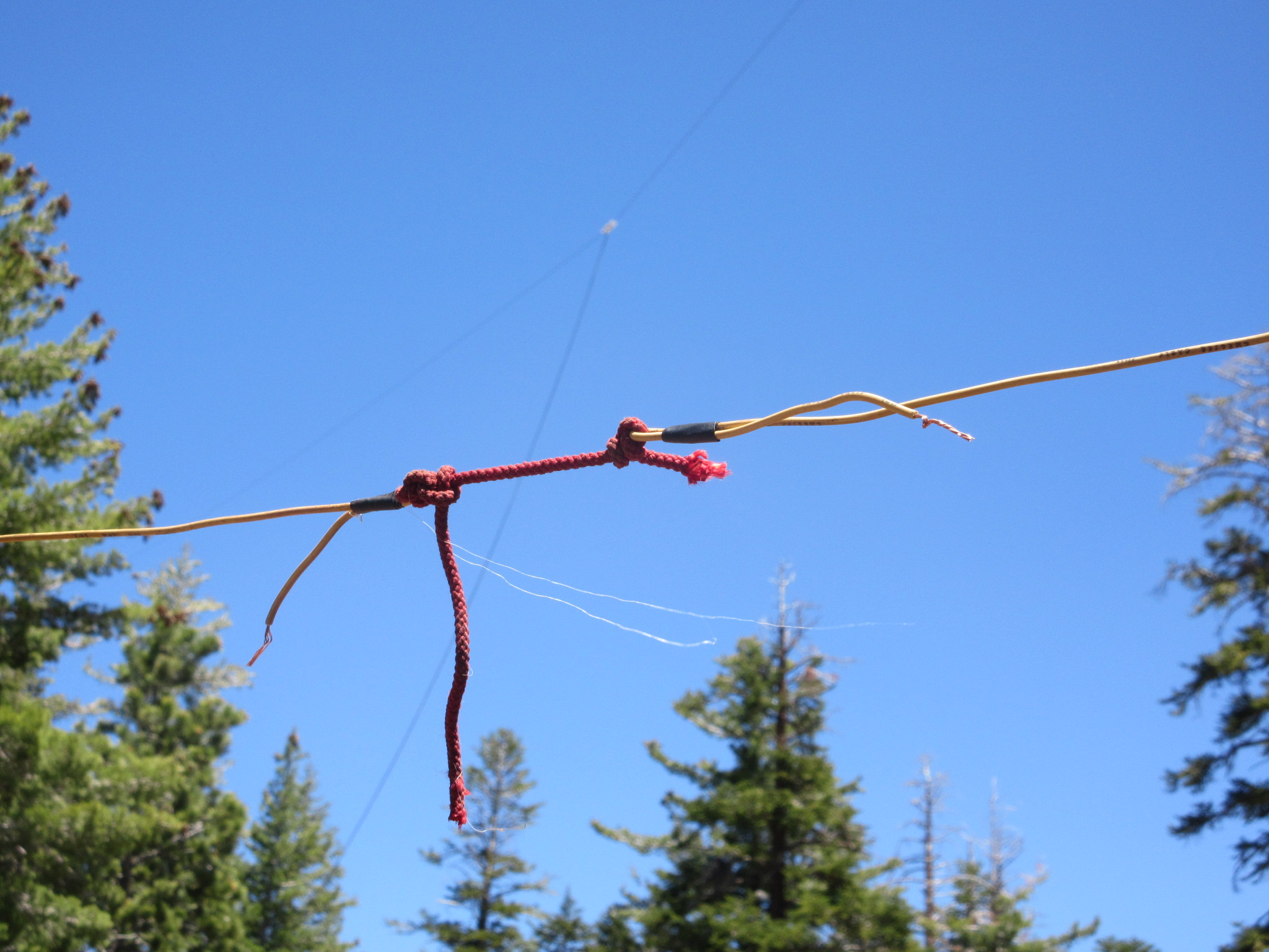
No problem. Cut the dipole legs for the 60 meter (or other higher) freq and reattach the remaining wire via an expedient insulator to isolate the remaining length. One for each of the 2 dipole legs. You can “re-jump” these insulators by twisting the wires together to go back to 80 meters.

Above: A short piece of 550 parachute shroud line tied in a loop connects the wire segments. One for each leg. A no-brainer. Or…..
The field expedient Boot Lace Bandswitch 2000:
Dipole or other wire-end expedient insulators? Because the highest voltages on a wire antenna are at the far end(s). Insulators? You’ve read the manual; Below:

For HF wire antennas, plastic spoons from C-Rats or MRE’s can work if they are all you have. The early white ones are not very strong but they illustrate the concept of field-expediency. Better to just cut the “handle” off and use only that part, see below. Best to melt the holes, say with a hot nail rather than trying to puncture them with a knife, the thin plastic splits easily. You get the idea, this is all common-sense stuff.

Above: An example of an MRE spoon handle used to insulate the end of some WD-1A/TT infantry telephone wire used as an Inverted Vee HF antenna.
As a practical matter, end insulators like these are really not even needed for a low powered HF field set. A 20 watt transmitter will not arc over at the antenna end or de-tune even if you are just using dry 550 cord holding up bare antenna wire. Or even just the insulation of field commo wire or similar. You don’t really need much insulation for the antenna to work at low power levels from say a PRC-104, 150 or even a PRC-47. It’s just good engineering practice and appropriate to highlight in a Field Manual used for training.
———————————————————————————————————————————————-
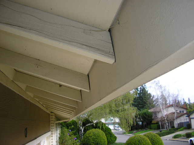
Above: Well maybe not a “Field” expedient antenna, more like a “Suburban” expedient antenna. See the wire connected to the rain gutter? Feed line wire attached with a sheet metal screw into the 80 foot long aluminum gutter. Works just fine on HF. Connect your gear to anything metallic and as long & high as possible – you will make contacts. For more info on the construction of portable, expedient antennas see Portable Field Antenna Kit elsewhere on this website.
PORTABLE VHF YAGI MOUNTING: Below is a photo of my portable 7 element Yagi for 2 meter field operations, mounted on a DIY mast bolted to the truck . Although not a “field expedient” antenna per-se, it can be mounted and aimed in the field in many expedient ways. The antenna is an old standard Cush Craft and it is mounted on top of an AB-85 mast.
In this photo I was using 18 feet of mast lashed to the back of my Bronco but the kit contains 3 nylon Guy Lines, stakes and hardware to make it self supporting on soil. (Not an option in this case). A short piece of Re-Bar driven into the soil keeps the bottom from kicking out when the AB-85 bottom section is slipped over it. It is fed by a length of RG-8X Coax and the SWR is close to 1:1 at 146 MC.

This is a very handy antenna and sets up in about 10 minutes, a little longer if free-standing and independently Guyed. In the below photo you can see the assembly. Everything is “standard” but I have put a shot of different colored spray paint at each element-boom intersection so is can be assembled quickly and accurately in the field.
Note that the mast section at the Boom can accommodate another AB-85 mast section – this allows insertion of my Dipole insulator above the Yagi if I want the mast to also support HF antennas. (this extra section keeps the dipole wires away from the Yagi elements – might mess up the radiation pattern an bit otherwise.

See the detail in this photo below. I have marked “MAX SIGNAL” arrows to assist others in properly aiming it if I am not around. The elements and boom-mast U Bolts are secured with wing nuts – no tools required for assembly. The camera lens “barrel distortion” makes everything look bent – all parts are actually straight…

Below is the same antenna (pre-paint job) deployed on a mountain top. The long canvas bag on the ground carries the entire antenna and mast. The 3 green “lumps” are the coiled up guy lines – not needed here. Looks like I didn’t get the elements very vertical – worked anyway! That vertical whip on the right is an AS-1729 VHF whip and coupler that I use for 6 meters. Here connected to the mobile VRC-7/RT-70 or the PRC-25. Good, rugged antenna system.
Speaking of the AS-1729 antenna, below is an example of a field expedient mounting: Bolted to a building versus vehicle, mast etc. This antenna is a center-fed dipole with the coaxial transmission line residing inside the lower half of the fiberglass whip. This is an excellent antenna system for VHF operation.

The MX-6707 antenna base is mounted via the lightweight aluminum vehicle mount attached to the building as shown. This antenna is currently tuned for 28 mc HF operation via the adjustable inductors in the base with the frequency selector manually set for the 30-33 mc band. I also have the 47.5-53 mc band adjusted for minimal SWR at 51 mc for work on the 6 meter ham band. The inductors are accessible in the antenna base unit:
For more information on the AS-1729 system look here: AS-1729/VRC


The portable Yagi as deployed on Crandall Peak, Sierra Nevada mountains.

Above: The same 7 element Yagi but with an expedient, but more sturdy type of mast mount. The lower AB-85 mast section is permanently bolted to the spare tire carrier; higher sections are simply stacked on it. Setup now takes much less time. This setup was used during a recent RACES simplex communications exercise from local high ground. That’s Mt Diablo in the distance.
This Yagi even works well during a solar eclipse!
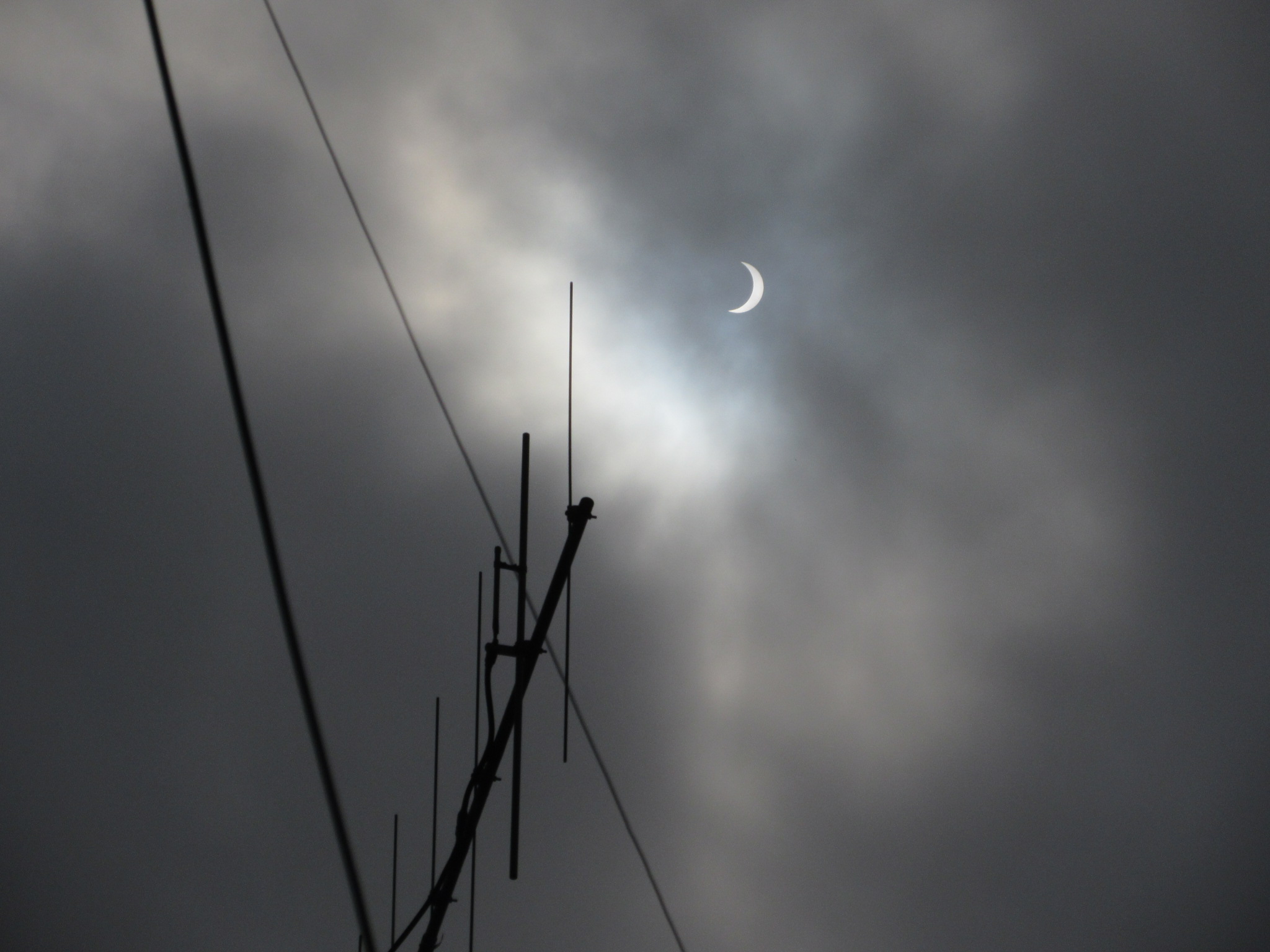
(I did not detect any reduction in solar flux noise on 145 mc during the August 21 2017 eclipse.)
The PVC Pipe J-Pole Antenna The standard J-Pole antenna for 2 meters is made from 300 ohm TV twinlead and fed by 50 ohm coaxial cable. They are handy – providing good gain over a “Rubber Dummy” and not requiring a “ground plane” or radials. The design is simple and available on many websites and handbooks.
I carry several, rolled up ready to hang from a tree or other support via a nylon cord launched with a small fishing weight. I can get these 50 feet up in a suitable tree when necessary. But there are times where you either don’t have a tree, don’t need the additional height or the extended range that provides. In that case, a free-standing antenna is called for.
I built one of my twin lead J-Poles inside a standard section of 1/2 inch PVC pipe to provide rigidity. Since the antenna is a bit longer than the standard 48 inch pipe, I added a 12″ extender at the top end with a female-female PVC coupler.
The antenna is held inside with a short piece of nylon fish line and topped off with an end cap sporting a stainless steel eyebolt. The eyebolt is opened up for hanging on a suitable support or tied to a line for hauling higher up. The bottom end consists of a TEE which allows the coax to depart the antenna at right angles thus permitting another piece of PVC pipe to be screwed into the TEE to increase the height and get the antenna “in the clear” if necessary. See details below.

One way I use it is to attach it to a piece of plywood to make it self-supporting, either on a table or on the ground. This set up is designed for a table where my ToolBox radio set provides a counterweight (not actually necessary – you could put the flange in the center of a wood base instead). The antenna is held aloft with an additional 4 foot PVC pipe extender which is screwed onto a standard 1/2 inch pipe flange screwed to the plywood.
If you don’t need the additional height, or want a stronger assembly, skip the 4 foot extender and just use a shorter male-male pipe section between the TEE and the pipe flange. Or you could just lash it to a table leg or anything else vertical. You get the idea…Simple, cheap, effective. See photo below.

—————————————–
Another very handy antenna that produces good performance on the VHF bands (and even the upper HF bands) is the “Jungle Antenna“. What’s the problem?
Experiments were conducted by the Signal Corps in 1944 in Panama and New Guinea and then updated and validated in 1964 by the National Bureau of Standards. The goal was to quantitatively measure the attenuation of HF and VHF signals through approximately 5 miles of jungle using an SCR-694 (GRC-9 predecessor), an SCR-300 (BC-1000) and TRC-1/2 sets. It’s a tough tactical problem. The conclusions from Reference 46:
“Attenuation due to dense jungle growth is so great
that for communication over distances greater than
approximately 1 mile the groundwave which is normally
employed for these ranges is practically useless.
Jungle communication greater than 1 mile
may be obtained by elevating antennas of VHF sets
either by raising them into trees or by using hilltop
sites. At VHF, horizontal polarization was found
to be preferable because of its lower absorption rate.
Ranges greater than 1 mile using medium or high
frequencies were found to require skywave transmission
using antennas radiating energy almost
vertically on frequencies reflected by the ionosphere.”
(The February 2018 issue of QST magazine has some good NEC modeling data on the absorption of HF radio signals by live trees/vegetation. Reference (70).)

Above: Triple canopy jungle is a really good RF energy absorber, especially on the higher frequencies. Try to get some site elevation (duh) but then rig your Jungle Antenna as high as you can to get it to be clear of the surrounding foliage. Because, down below, even if the sun can penetrate a bit:

Above: This stuff saps your energy – and also your antennas’ radiated energy. This wet stuff will absorb all the radiated VHF signal before it goes 100 meters.
Here, the words of Clausewitz [Mandatory quotation] become obvious:
“Everything is very simple in war, but the simplest thing is difficult.” Indeed.
If you are slogging your way through this stuff, “antenna design theory” nicety might have to go out the window at the expense of performance. Just try to get some wire UP with the supports, time and energy you have. Or head for that little hillside clearing, about 2 Klicks off in the distance, your extraction LZ, 195 degrees magnetic. In jungle like this, finding and setting up any antenna in a clearing like that one will help a lot in getting signals in-out. Since all known VHF man pack sets utilize vertical antennas, let’s stay with that convention.
The Jungle Antenna is easier to build than to describe, but here goes: It is simply a 1/4 wave ground plane antenna made with wire elements versus the traditional metallic rods. The military RC-292 ground plane antenna is electrically equivalent. The Jungle Antenna is intended to be fabricated with locally available materials as a field-expedient when you are operating beyond the end of the logistics stream – you know, where YOU are….
However, it can be pre-fabricated before deployment using more appropriate material. It can be cut to the proper lengths per your Comm Plan freq if you know it in advance. The Jungle Antenna is useful and will work well over any terrain, especially if elevated above local vegetation.
Field expedient materials could be demolition wire, WD-1/TT, WD-1A/TT field commo wire, bare copper or any other suitable wire. Insulators can be any non-conductor such as MRE spoons, plastic water bottle strips etc. as noted above. You’ve read the manual…
For feedline you can use insulated field commo wire pairs, “zip cord” lamp wire or speaker wire pairs as well, although coaxial cable will produce more repeatable results. The antenna I built will easily handle 100 watts of RF power. But this is the “deluxe” model – made beforehand, back in the rear with detachable connectors, coax cable feedline and insulators. Also assisted by soldering some parts together. You can make an electrical (and performance) equivalent with just WD-1A/TT or other commo / demo wire. Improvise, adapt, overcome……

Above: Example of a rolled-up Jungle Antenna cut for 29 MHz. Made from individual conductors from WD-1/TT commo wire. The BNC connector joins everything together and allows RG-58/U coax to connect down to the radio. Works great, lightweight, pre-cut for this frequency band. It will also work well on the 27 MHz “CB” band if you need to go that route.
I’ve gotten a lot of inquiries about the design of this type antenna, so here goes: Electrically, the antenna consists of a vertical 1/4 wavelength long radiating element and three (or 4) 1/4 wavelength long “radials” that come down from the center feed point at about a 45 degree angle down from the horizontal. That angle is not particularly critical but it does affect the feedpoint impedance; 45 degrees is about right to produce 50 ohms, your desired target if you are using 50 ohm coaxial cable to feed it (from your 50 ohm output radio). The Jungle Antenna is designed to be suspended from a suitable non-metallic support like a tree and elevated as much as practical to get it high and in the clear of other objects.
(Note that this is primarily a “narrow frequency” antenna. For a given antenna (lengths) , its impedance changes as you change the radio frequency from the antenna-design frequency. So it’s not optimum if you are running a 30-88 MHz frequency hopper like SINGCARS in the Hopping mode. But if it’s all you have, an antenna like this cut for mid band will work. It’s not an OE-254 broadband antenna, but you probably don’t have one of those handy either.)

We’ve all seen drawings of it in the Field Manuals – Is that an antenna or a deadfall? A particularly useless drawing. But how do they work?
The following photo’s show a handy Jungle Antenna fabricated with 4 pieces of 20 AWG insulated wire, an insulator at each end of the vertical radiating wire and the 3 radials connected to a common “ground” point at the feed, in this case a standard SO-239 coaxial connector. The antenna is fed with a 20′ piece of RG-58/U, 50 ohm coaxial cable with matching PL-259/adapter connectors at each end.
The 3 radial wires are spaced apart and held at the appx. 45 degree angle with 3 pieces of thin bamboo arranged in a triangle. Bamboo lengths are about 5 feet each at this frequency; size them to get about 45 degrees spread on the radial wires. Use local non-metallic materials. The radial wires are tied to the 3 apex’s of the bamboo triangle which hangs parallel to the ground.
The radiating wire top insulator is tied to a nylon cord lanyard thrown over a suitable tree branch for hoisting the assembly up. For maximum range, hoist it as high as your feedline permits. (By the way, the “ground stake” shown in the above illustration is unnecessary for the proper operation of this type antenna. Although generally a good idea from a “safety” perspective, ground plane and dipole antennas performance is not significantly enhanced by grounding the radio.)
Below is a Jungle Antenna at my backyard “antenna test range”. Hung from a tree so the feedpoint was about 18 feet above ground and about 15 feet away from any metal objects. I used the antenna impedance meter to measure the impedance at the design frequency of 51.0 MC. The antenna measures 51+j0 ohms, close enough to 50 ohms, yielding an SWR of 1:1, the desired outcome within the accuracy of this meter. What does that mean? It means that this antenna will efficiently radiate almost all of the transmit power you send it. Your goal.
The white object is the lower insulator, the silver PL-259/SO-239 connections are visible with the black coaxial cable heading downward. The gray wire is the 52 inch vertical radiator wire, 3 black wire radials are evident. The green nylon cord ties the SO-239 to the insulator, taking the strain off the soldered wire connection (the insulator is not electrically necessary, the knot has insignificant inductance here). The 3 black radial wires are soldered together and then soldered to the “ground” flange of the SO-239 to form the ground plane. See below photo’s.

Below is the Jungle Antenna hanging from the tree, viewed from below. The 3 light weight bamboo radial spreaders are evident. The coaxial cable feed line hangs through the middle of the triangle and goes down to the radio. Use local (non-conducting) materials for the spreaders.

Below: Photo showing connection of one radial wire to the triangle corner. Simple…Rubber band or local twine to secure, loop radial wire under end. Of course, wrap more securely for long-term ops or windy conditions. The wire insulation and the dry sticks serve as the “insulators” on the ground radials. For under 50 watts or so, this is adequate. If you want to get fancy, use an insulator of some sort, this is a high-impedance (and therefore high voltage) point. Especially if you make the antenna from bare, uninsulated wire. Ditto for the top of the vertical wire.
If you are really in a hurry, can’t find any suitable sticks, or need to be super lo-visibility, just let the radial wires hang down by themselves. The antenna then becomes a vertical, (center fed) dipole which works pretty well too. Maybe even a little more broadband than a jungle antenna.

This blurry photo shows the antenna impedance meter while the antenna is under test. It reads the complex impedance as 51+j0 ohms, indicating resonance at 51.010 MC with no reactive component. Close enough. (The fact that the resistive component is 51 ohms at 51 MC is just a fun coincidence – no significance). The resulting SWR is 1:1

Stowed, ready to transport. Wire parts weigh practically nothing, will fit in a BDU pocket.

As an electrical equivalent of the RC-292, the range improvements should be essentially identical. (Actually, it’s even better than the RC-292 since you make the radiator and radials the exact length for your pre-planned frequency. The RC-292 uses fixed-length steel elements which are a compromise in performance – that causes feedline losses). The RC-292 manual states that two PRC-25 radios, each equipped with an RC-292 should expect 12 miles range of over “average” terrain. The planning range of two PRC-25’s operating with the AT-892 “tape” antenna is 5 miles. So the RC-292 can be expected to at least double the range available by comparison.
A jungle antenna at the same 40 foot height should produce similar range results. Get it high, in the clear, away from other objects, especially metallic ones. I can get into 51 MC Ham repeaters in the Sierra Nevada mountains from here using the Jungle Antenna and a 5 watt transmitter – over 80 miles away. (The repeaters are up around 2500 feet AMSL, I am near sea level but there is other terrain blocking the LOS path).
Expect long range but your mileage may vary. (My military and Ham experience with these radios tells me that “12 miles over average terrain between RC-292 – equipped PRC-25 radios” is VERY conservative.) Below: Rigged prior to hoisting it up.

This antenna WORKS! If you have the luxury of building your antenna with coaxial cable feedline and BNC connector, it connects directly to the radio (just like an RC-292) as seen below:

The “really field expedient” Jungle Antenna: You can also make the antenna and feedline from “assault wire”, WD-1/TT, WD-1A/TT, whatever you have and little else. It is your more likely parts source since it is widely available in the field, beyond the end of the logistics lines. You know, where YOU are STILL located! In that case, the 3 radial wires are all made from the wire and the “feedpoint” ends are twisted together and connected to the feedline to the radio.
This is the “ground” wire. The other wire is the vertical “radiator” and it is not connected to the radials; it continues down to the radio on the other conductor of the pair. Easier done than explained. However, make sure you identify which wire in the feedline is the actual vertical radiator. This is done during construction by following this wire down to the radio end and “marking” it with a knot. “The Knot is Hot”. See below

“But Chief, how do I connect the Jungle Antenna to the radio? This antenna feedline has no connectors!” Note the knotted “hot” conductor is connected to the radio antenna terminal using the tape antenna flexible mount screwed in to keep it in place. The other “ground” wire which is connected to the antennas radials is connected to the radio chassis – here under the screw that holds the BNC connector dust cap chain.
In this case, use this method for the PRC-25, or 77 radios. When connecting up a Jungle Antenna do not use the hard rubber AB-591A/PRC spring from the long fishpole whip antenna to connect the hot wire to the radio. That brass stud sticking out the bottom (seen above) operates switches in the radio to reconfigure the matching circuits to the fishpole antenna. Not what you want. Use the AT-892 as your “bolt” instead. (of course, remove the steel tape antenna from the spring mount first – you don’t want or need it now)
For more modern gear like the SINGCARS series (and operating in a non-freq hopping mode), you need to push the center “hot” conductor into the front panel BNC female connector and figure out some strain relief so it doesn’t fall out. The “ground” wire which is connected to the radial wires needs to be electrically connected to the radio chassis.
Find a “screw of opportunity” on the chassis – make sure something doesn’t fall off when you loosen it for the ground wire! Figure this out in advance. Or better yet, carry an adapter like a Pomona BNC-Banna jack adapter. These new VHF radios have a thousand “Bells and Whistles”, but no dedicated grounding lug. (If you are using a PRC-104 or PRC-150 Falcon, you are good to go with its ground lug.)

In the above setup I was using WD-1A/TT field telephone wire. It is made from 2 wires bonded together like lamp “zip cord” rather than the 2 individual wires of the older WD-1/TT wire. Either type works fine.
Another long range VHF antenna is the AT-984A/G long wire antenna. Strung about 4 feet above ground over its 150 foot length, the antenna radiates best in the direction(s) the wire is running, away from the radio. TM11-5820-667-12 states that a pair of PRC-25 (77) radios equipped with these antennas can expect ranges of 17 miles between them.
Awhile back we ran some experiments between a PRC-25/AT-984A/G set and another PRC-25 with the AT-271A/PRC 10 foot fishpole antenna at the other end. Over a nearly-optical line of sight path, we had solid 2 way comms over a 131 mile path. Pretty optimum path however, elevated terrain is your friend. See the Category “Radio News” PRC-25 Hearability Tests posting elsewhere on this website for details.

Above: The AT-984A/G. It consists of 150 feet of uninsulated stranded phosphor-bronze wire wound on a modified fly fishing reel for storage and unwinding. It has a spade lug on the radio-end for connection to the radio antenna jack; a nylon line for the “insulator” at the far end.
In this case, the manual advises the use of the AB-591A whip antenna spring base as the connection “bolt”. This part configures the radio’s matching circuits for better power transfer with this particular antenna.
While the AT-984A/G is an NSN-stock antenna, you can make a simpler field-expedient one by just using 150 feet (or more) of insulated WD-1A/TT field telephone wire instead. It is lighter (but harder to store) but is also insulated, a useful feature when everything is wet around the antenna. Not sure why the stock antenna uses bare wire – I certainly would have made it with insulated wire instead. Keep it off the foliage – these radios only put out about 2 watts, none to waste.
A field expedient version is just 5 or more wavelengths of wire operating at your lowest planned frequency. Longer is better and also more directional (you need to aim it near the correct azimuth accurately.) Configured as a long wire or supported in the middle as a vertical half-rhombic, these antennas will stretch your maximum range. Those antennas are bi-rirectional along the azimuth. If you terminate the far end with about 600 ohms to ground, that reduces the signal in the reverse direction. Run a ground wire under it if you can.
A single-wire antenna such as this will perform better if the radio is “grounded”. Here’s a quick field expedient to meet that need:

Above: If you do use/need a “ground” connection, here is a simple solution for your bag of field tricks. It is just a 12 inch aluminum mast/tent stake with the paint sanded off. Drill a hole for a 1/4 – 20 machine screw, nut, 2 flat washers and a wing nut – add your ground braid wire and a big alligator clip. Dig a fist-sized hole in the soil, fill it with water and pound the stake in the bottom. If you have a couple of salt packets from your MRE, sprinkle some in with the water and keep the soil wet.
Not a great RF ground, NEC-compliant AC power ground or a lightning ground – but it is quick, dirty and vastly better than nothing for an on-the-move system that needs a “ground”.
Important: Adjust the wire length between the stake and the radio to keep it as short as possible to minimize the inductance. Lay out the remaining wire on the ground to assist as a “radial”. Or just reverse the wire and clamp it to a local grounded water pipe, steel structure, any metal in good contact with the soil. Connect other end to radio without using the stake. Incidentally, this makes a very functional ground connection for a fox hole or crystal radio in the field. The stake can also hold down your hootch – dual use.
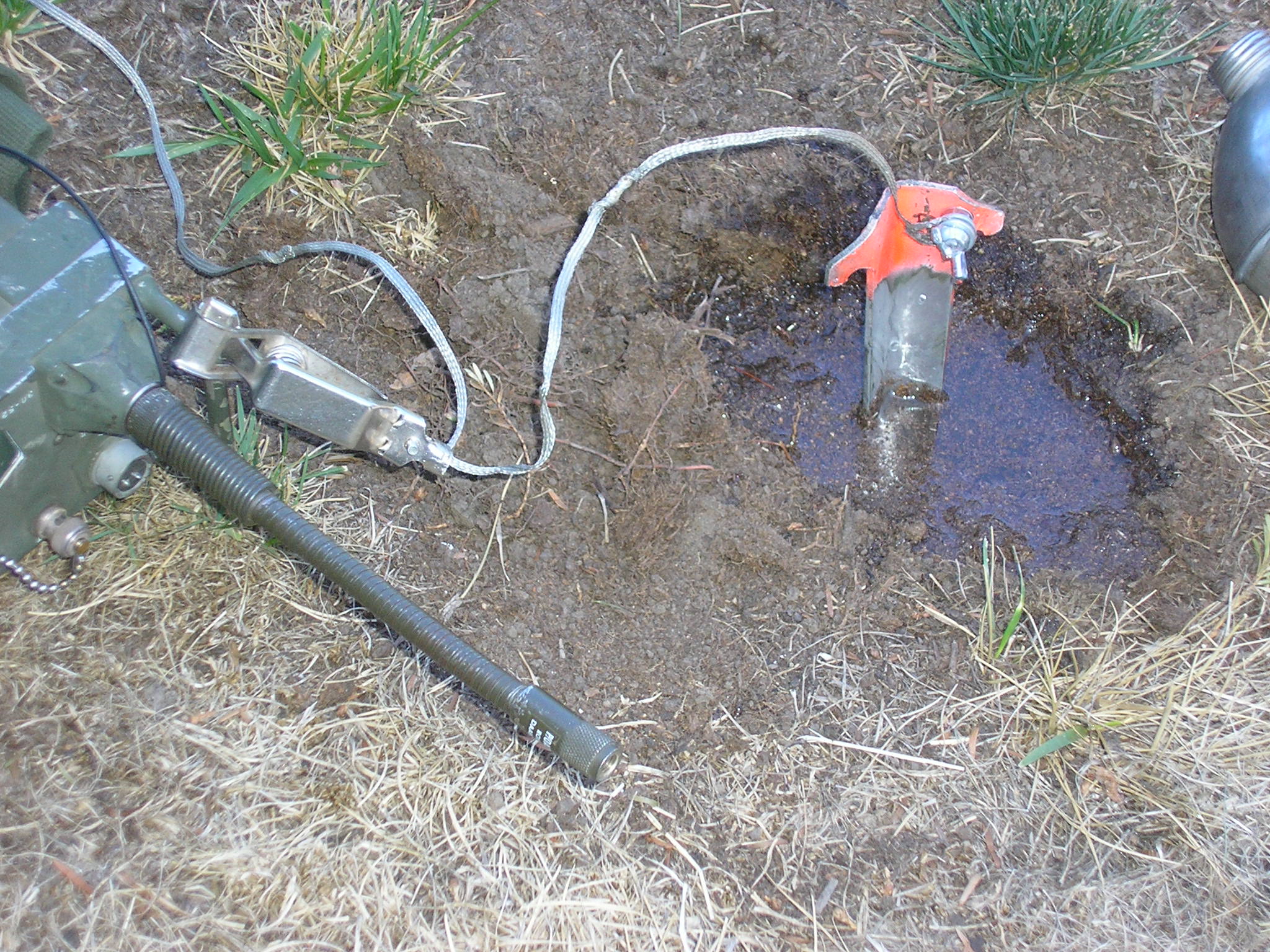
Above: You get the idea…Hammer that stake all the way in. If you humped in an E-Tool that you then used to dig the hole, you can bury the E-Tool blade and use IT for a ground.
Above, the stake used to ground a PRC-25 while rigged to a half-rhombic antenna. Lay the excess ground wire directly under the antenna wire, preferably all the way to the other end of the antenna and its termination resistor. As always, keep the connection between the ground stake and radio chassis as short as possible.
A field expedient “ground” solution for any HF radio such as a TRC-77, PRC-47, PRC-150, GRC-109, SCR-284, RS-6, PRC-104, PRC-74 etc. It will keep the chassis from biting your fingers with RF too. If you use a big alligator clip like that, make sure it bites through the paint on the radio chassis. Or wire directly to the sets’ ground post like on this TRC-77 HF CW set:

“Fifty percent of the time Comm works all the time”.
———————————————————————————————————————————————————————————
Temporary HF Mobile Antenna mount
I needed an “quick and dirty” expedient HF whip antenna mount for my Ford Explorer for use on an upcoming trip. It needed to work primarily on 40 meters and I wanted to use MS-116, 117 and 118 antenna sections that I had on hand. Since these sections are used for other radios, I did not want to modify or damage them in any way.
I had an AB-652/GR antenna base from the GRC-106 system and I wanted to mount it on an existing trailer hitch and the little 1-1/4 inch receiver. So a little scrap metal and other junk box parts and I had something going. Total cost beyond what I had on hand? Zero.

This shows the mast base with included spring attached to the trailer hitch. There is a 1 microhenry matching coil from the antenna base to ground. The banana jack and plug makes a quick-disconnect cable for the Hot lead and a wing nut for the ground strap to the vehicle chassis. This is pretty temporary for now so the matching coil is made from PVC with the turns held in place by hot glue.
Incidentally, that coil to ground also bleeds off the static electricity the antenna collects while moving. It keeps the noise level down, especially under dry conditions or while snowing.

The above photo shows the Air Dux stock loading coil, approximately 30 microhenries. The coil is captured between two pieces of plexiglass held together with 4 fiberglass rods tapped for capture nuts. The alligator clip was later replaced with a soldered connection once resonance had been found. The two mast sections are held in axial alignment by a 1/4 inch diameter fiberglass “flag whip” sold for kids’ bicycles. Nearly perfect fit. This rod also serves as the required insulator between the two mast sections. I also used this fiberglass rod material for the coil end plate connections.
This shows most of the overall antenna with the loading coil about 1/3 of the way up the whip (the MS-117 and 118 sections are above the coil). The antenna length is 9 feet with the top about 11 feet above ground. It is guyed to the vehicle during travel since it is pretty flexible and I wanted to keep its impedance within limits as it bent back at-speed. The trailer hitch keeps it pretty far from the vehicle body which helps keep the “Q” up and it reduces the capacitive coupling to the vehicle. It also permits the rear window to be opened without hitting the antenna.
It works well on 40 meters and with a simple Tee tuner in the vehicle it tuned up on 30, 20, 15 and 10 meters as well.
Hmmm, If I add two MS-116 sections below the coil I can bend it forward over the roof of the vehicle and tie it off to the front bumper. This would permit the reduction of the loading coil inductance (lower losses) and it would work great for NVIS comms.
——————————————————————————————————————————————————————————-

Above is a shot of the completed HF ricebox comms system in the COMM / NAV / EW crewmans position in the family Grocery Getter….Includes GPS for NAV and a CB to collect trucker Intel…I have included a “strap on” antenna tuner that is used while operating in fixed positions to run dipoles or long wires or to use the whip outside its designed frequency range. Note the field-expedient hacksaw blade keyer paddle mounted upside down under the transceiver; dot and dash positions reversed by menu software.

Shake down cruise: Field Day 2011 HF mobile Ops on Mt Diablo. Worked 18 states from Connecticut to Hawaii, all on CW in about an hour.
UPDATE: We took this rig on a 3500 mile road trip to Montana with the HF whip enduring 65+ MPH winds on the back of the Explorer while underway. After 3000 miles the center fiberglass dowel finally chafed through and broke, resulting in the upper part falling down. A quick change over removed the loading coil and I simply screwed the upper MS-117 into the lower MS-116 and we were in business again. The antenna tuner could handle the resulting impedance (albeit inefficiently) and we were back up on the Net. It worked great as a temporary design – now I have to build a stronger whip-coil mechanical connection. See below:


Above: The field expedient HF mobile antenna mount; pretty close to a great ground, the Pacific Ocean! Pismo Beach CA. Nothing to see here – move along.
RYRYRYRYRYRYRYRYRYRYRYRYRYRYRYRYRYRYRYRYRYRYRYRYRYRYRYRYRYR
Inverted “L” Antenna System
One of my workhorse antennas is an Inverted L although it does not have the “system efficiency” of a resonant dipole. This one was an expedient installation which became permanent due to my available supports locations. Made with 26 AWG wire with gray Teflon insulation is is all but invisible.
It runs about 25 feet vertically and then about 75 feet horizontally plus another 62′ horizontal “dog leg” utilizing available trees, “working against” ground. This keeps the high current portion in the horizontal wire where the max radiation takes place. I ran a half wave WD-1A/TT “ground bounce” field telephone wire along the ground directly under it to improve the vertical gain against my very dry soil. An improvement of maybe 1-2 db (L.B. Cebik)
The wire runs an average of 1/10 wavelength high above my ground wire – this is a good compromise elevation for gain, noise rejection and supports availability.
But it is shorter than the original 192 feet I had installed since the far end ran near a neighbors house and picked up all kinds of electrical hash emanating from their computers, monitors, modems etc. Shortening it solved that problem pretty well without noticeably impacting signal strength.
It is a good NVIS antenna for my main interest in regional comms from zero out to about 300 miles on 80 meters when the Critical Freq is in the 4 MC range or a bit higher for that time of day. It also has a vertical component that is usable for longer distances – but I am not into DX that much.
The EZNEC model tells the story and I find it to work as predicted. I want the Max radiation straight up at the exclusion of low angle arriving “DX” and noise from distant lightning static crashes. The Dogleg gives it a slight “bulge” off to the northeast/southwest. The antenna is quiet and very effective for me.


The azimuthal pattern is within 2 db of being circular, also what I wanted.
The radiation patterns are even pretty similar when used on 60 meters.
I have it tuned to the West Coast Military Radio Collectors Group CW freq of 3550 kc. At that freq, it is shorter than 3 quarter waves for a classic inverted L. EZNEC gave me an estimated feedpoint impedance calculation and a place to start with an L Network matching system.
Plotted on the Smith Chart, this complex impedance can be transformed to 50 + J0 ohms with an L Network consisting of a series inductor from the transmitter and a shunt capacitor across the antenna terminal to ground. It works out to about 20 microhenry’s and about 85 picofarads in its current length, height and environment.
Doing some preliminary experiments with an L Network:

Above: I’m constantly experimenting: Here with a breadboard L network at the base for different frequencies and different antenna lengths. An impedance meter, Smith Chart graphic “ruler” and my trusty HP “reverse Polish” scientific calculator makes it easy to tune to 1:1 base SWR.
I built a prototype inside a clear plastic cashew jar from Costco to keep the parts dry, using a blob of silicon grease on the jar-top threads. It was configured using a 100 pf variable capacitor and a piece of junk box Air Dux inductor. It tuned right up to 50 + J0 at 3550 KC, SWR=1:1 It can operate about 95 KC above and below the design freq while maintaining an SWR under 2:1, indicating a pretty high Q.
With the variable capacitor and the moveable inductor tap, I can tune it to any freq in or around the 75/80 meter band without changing the basic configuration. It is currently tuned to my standard CW freq of 3550 kc; the West Coast Agent Guard Channel (nights).
The resulting assembly is housed inside an inverted flower pot to keep the sun off the plastic and to protect it from mechanical damage. Also provides a bit of camo – “Pay no attention to that flower pot with the wire protruding from the hole in the top”. Works great and provided good refresher training in the use of the very clever Smith Charts.

Inverted L antenna matching network built inside a plastic container. The air variable capacitor tuning knob is on the back (bottom). The transmitter is connected to the inductor via a lug on the red plastic cap. The red end makes it potentially usable in Mil-Spec shipboard applications, red indicating a transmitting antenna! ;0) Costco thinks of everything!

The other end showing the gray plastic tuning capacitor knob and banana plugs for the antenna and transmitter connections. The ground lug is a stainless steel bolt with wing nut connected to the ground system. The white ceramic insulator takes the vertical strain from the antenna wire. A bit of black rubber hose provides chafing protection for the wire versus flower pot. The coax is buried.
As with all similar “single ended” wire antennas, make sure you have a good ground system at the feedpoint. Connect the ground radial wires to the coax shield and “ground rod” at the antenna base. This boosts the radiation efficiency by reducing ground losses.

Ever-changing antennas and experiments: A modified Inverted L antenna was subsequently installed. It was longer than a resonant antenna on 3550 kc so it is therefore inductive. I measured the base impedance as 20+j200 ohms. Need to match that:

To match that particular antenna configuration to the 50 ohm line Mr. Smith (Chart) tells me that I needed a 1.8 micro henry inductance across the coax and then a series 200 pf capacitor from the coax/coil point out to the antenna. With a mica compression capacitor it tuned right up, 1:1 SWR for my 10 watt AN/TRC-77 and AN/GRC-109 CW radio sets. The plastic food container keeps things happy in the weather under the flower pot.
Here’s another more permanent, adjustable solution for expedient antenna experiments:

With this “Inverted L” arrangement the antenna is very quiet during the daytime and dawn/dusk periods. When the band “goes long” in the evening hours the vertical component begins to pick up some atmospheric noise (and signals) arriving from low angles beyond NVIS range and it gets a little noisier. Overall a good performer for me for my main interest of 0-300 mile regional coverage.
If your supports cooperate for an “NVIS” Inverted L system, make the length such that a current loop (max) occurs in the horizontal portion (versus vertical or slanted portion) to provide a high radiation angle when placed about 0.2 wavelengths above the ground. For regional coverage this is why the Inverted L out performs any end fed “slant” wire which wastes lots of power into useless slant elevations and random azimuths. Consequently:
I am not a fan of end-fed half wave (EFHW) slant wire antennas for a number of reasons. But with limited supports geometry or an interest in casually contacting “anyone, in some directions and at some distances” they can sometimes be useful. Below is my portable one suitable for temporary installations. BNC jumper to the radio, Banana Plug to the transformer, alligator clip for the ground radial. Some specific details on this one here: N6CC Field Antenna Kit

The above antenna is made with 132′ of WD-1A/TT field telephone wire (both conductors tied together at each end). It includes a small 49:1 impedance matching transformer with an FT140-43 ferrite core suitable for my low power military field sets. Thin, dull and O.D., it can be “stealthy” if needed.
BT
NNNN
——————————————————————————————————————————————————————————–
Wire dipole length calculations.
Every tactical HF radio operator knows that the formula for calculating the length of an HF half-wave wire dipole is L = 468 / f Where L is the overall length in feet, f is the frequency in Megacycles and 468 is an empirical constant, k. Usually. That’s probably close for a wire dipole in “free space”, probably one-half wavelength above “ground”, wherever THAT is…. (If working in metric units use L=143/F to give the overall length in meters.)
So I built one for the new 60 meter band. 5.357 Mc to be exact. So overall length should be 468 / 5.357 = 87.36 feet as a starting point. The feedline is RG-58 at a random length of about 40 feet.
(Yes Your Honor, that coax line performs as an impedance transformer since it is not an integral number of half-waves in length. I refer you to Mr. Smith <chart>). But let’s continue, assuming that the resulting dipole looks like 50 +j0 ohms at its terminals when I’m done. Big assumption. But in that special case, the electrical length of the 50 ohm feedline does not matter.
Upon building and installing it at a height around 18 feet average (going for an NVIS system here) it resonated at 5.535 Mc, looking into the same feedline. Too high; the antenna is obviously a bit too short, resonating at the higher frequency. The “error” is not surprising, considering its height and proximity to a building and other wire antennas. But how much longer should it be for 5357? You can use this info to find the correct numerator constant for THIS installation.
Solving for the new constant k, k = 87.36 x 5.535 Mc. This equals 483.53. That’s the new constant to use now.
So, NEW length = 483.53 / 5.357 = 90.26 feet overall; each leg = 45.13 feet. So 87.36 + x = 90.26. x = 2.90 feet to add to the overall antenna length. That’s 2.9 /2 = 1.45 feet to each leg.
So I did that, lengthening the antenna accordingly and restringing it in the same place at the same height. Presto! New resonant frequency is 5.359 Mc, close enough for a ship this size….The feedline input impedance is now 48 + j0 Ohms at 5.359 Mc; essentially a VSWR of 1:1; no lossy “antenna tuner” required – and it works great. System “Q”? It is within 2:1 VSWR between 5.240 and 5.608 Mc so it is more that adequate across the entire 60 meter band.
No rocket surgery here, just an acknowledgement that a rule-of-thumb can be sharpened with actual measurements and then re-applied. I’m sure I’m not the first one who has tweaked the formula but it’s pretty apparent how it works..
So, What’s the BEST antenna? The one that WORKS!
BT
NNNN
Congratulations! This is the true “spirit of amateur radio”. Wonderful and amazing suggestions. 73´ from Crezivando JUNIOR PP7CJ (Maceio-Alagoas-Brazil)
Hi – and Thanks!
Well, no really novel designs here and certainly no new theory or science – just basic, proven designs put to good use. I guess my overall point is “simplest works best”. I routinely use these antennas while camping and exploring and they have worked very well for me.
Thanks for visiting my site & have fun!
73, Tim
thank you my frıend.
73, HAYATI
TA2VW
Thanks for visiting – Have fun!
Tim
Awesome.
Never have I seen field expedient antennas so easy. I’m a 25C in the Army and this is what we are known for. I’ve been giving blocks of instruction and conducting missions with these basics for 4 years now. Your “Macgyverism” with antennas is what I strive for. Truly awesome work.
Thanks Zach – Hope you can find it useful…Keep your antennas up and your heads down!
Thanks for your service…
Tim
Cool! Nice to see some of this stuff. I was AF Combat Comm. I remember slapping together some “field expedient” antennas using field wire in Central America for HF, and also many years later in the mountains in Colorado (not work-related :)).
Fun stuff.
73,
Rick, N0NJY
Hi Rick – Thanks for visiting – and Thanks for your service!
Improvise, adapt, overcome…….
Great write up. I looked at your “about” page and it says O.K. to post material with link back. So wanted to confirm. I would like to repost this article on our communications website and provide link back to this article and also give photo credit. Thank you-
Hi Sally – Thanks. Sure, OK to use with “credit”, that’s what it’s for. No Rocket Science here but basic practical stuff that I hope someone can use. Always looking for feedback, corrections, additions etc!
Thanks for asking…
Tim
Great Website. I was a 31V in the Army and often created field expedient antennas for PRC77’S and vehicular radio configs during the slow times while in the field. Thanks..
Hi Jim – Thanks for visiting –
and thanks for your service Soldier!
73, Tim
Hi Tim,
Just wanted to say thanks for the info! I have a bit of a question – I spent ~10 years as a Cav Scout in the army, and one of the tricks I learned early on was to take a length of commo wire, splice an mre spoon into one end of it, and use a rock to get that sucker as high up in the tree as you could! At the time, it all seemed to be mostly ‘black magic’. Now that I am working my way into HAM after the army, it’s starting to make sense. Just wish they had taught a little more theory, and less ‘follow the magic recipe’. Anyhow, Thanks a lot for the awesome info! You obviously have a ton of great experience, and kudos for sharing it!
Ron
Hi Ron – Thanks…Antennas have always been interesting to me – they are usually way more important than the simple transmitter-receiver in getting Max range…. Yep, the military has great schools for the task at hand but getting further into theory takes a lot of time, and the bad guys are not waiting as you know. But theory is one thing – putting it to practical use is another…
Good luck with your Ham studies and thanks for your service!
Tim
I loved your informative display of field expedient antennas. You can teach a lot to many and it will be appreciated. From one communications guy to another, thank you.
Hi Henry – Thanks for checking in…Glad you liked this stuff, antennas are always fun to experiment with.
Tim
Hey this is great stuff. I am in Alaska but from SLO/Pismo area and I found this today and showed my soldiers – you can antenna anything!
Hi Nick – Glad you could find some of this to be useful. It works for the Navy – probably the Army too! HaHa
Thanks for checking in and thanks for your service.
Tim
Can you send me some diagrams of field expedient uhf antenna?
Hi Kelly – Sure, personal message sent with details. Also a web search on “UHF Ground Plane Antenna” will show many possible designs but they are all pretty simple.
Semper Fi,
Tim
This a great site and one of the most interesting ones I have found relative to radio. A Qrp cw operator on this end for over 40 years and with lots of HF field experience, I still learned a lot. Hope to work you portable some time. 73 AA0RQ
Hi Bill – Glad you found some of it useful. Experimenting with antennas is fun, and practical.
If it is a conductor, and up in the air, it’s an antenna – especially on HF. It doesn’t take much…
73 Tim
Hey brother, Really like the page.
I am a 25U in the Army.
I was wondering if you had anything in the way of a class that you can share with me??? I am pitching it to my Squadron Commander and CSM tomorrow afternoon.
Hi Robert – Thanks for checking in. Hope you found some of that useful. I’ll respond off-line.
Thanks for your service!
Tim
Amazing page. Great implementation of some tried-and-true designs. I learned a lot and can’t wait to op-check some of these antenna applications when I get back to the States. I work in signals intelligence and am also a HAM operator. I was wondering if you have looked into software defined radios (SDR) at all? If you have a phone or tablet running Android (at least that’s what I’ve been using) you can get eyes and ears on a big piece of the spectrum with a USB receiver, an antenna of your choice, and a free app like Soft Touch SDR. The setup would definitely look great in your geared-out 4×4 console. Again, great page and much respect. Thanks and Semper Fi.
Hi Scott – thanks for checking in….I have used some of the remotely operated SDR receivers here in CONUS and I’m very impressed. Currently looking at one to experiment with here, as you suggested. Nothing better for Situational Awareness HaHa. A far cry from scanning the spectrum with an R-390 and a case of carpal tunnel syndrome!
The technology is changing rapidly and costs are very low, it’s a Candy Store out there….
Thanks for your service Marine, we’re with you.
S/F. Tim
Consider this site “bookmarked” and shared. Thanks for the information
Most “creative” HF antenna I ever used in a “service” environment, was a five-strand farm fence strung between hardwood posts. Not likely to work near as well with fences strung on steel star pickets.
“Hot” wire bare-end wrapped several times around a buffed-up short portion of the top strand of the fence and about sixty feet of field telephone wire run out on the ground at right-angles to the fence as an “earth”.
“Tactical” too, no digging, hammering, scruffing up trees, or worse, getting a huge dipole or inverted “V” stuck up in the air and not being able to recover it.
Worked a treat, with a deft bit of tuning at each frequency change.
Hi Bruce – Yep, an antenna that also manages livestock! Barbed wire or any kind of wire fence begs to be used as an HF antenna. Using the simplest, available materials to get the job done. Nice..
Thanks for visiting! Tim
I swear to God we went to different high schools together!!!!!!
I don’t have a website. Long story. OK, I’m lazy!
Reading through your postings is like a re-education on RF electronics. Your comments regarding vertical antennas are slightly off. A vertical antenna is: “An air cooled, omni-directional, vertical polarized, dummy load!!” And you are correct, they don’t work that well except for DX and even then only when properly installed above a radial counterpoise.
There are some real gems in your writings. I have two sets of what I think is fiberglass antenna mast sections (allegedly from the IDF) and they came with a VHF ground plane antenna cut for about 80 MHz. I trimmed mine down to 2M and I can go up a total of 40 ft. Nylon braided guy wires are included but, like you, I use a ground mounted piece of 3’4 inch plywood with a pipe flange and I run one of the rear tires of the truck over the wooden piece to secure it. The mast is secured on the roof rack on the truck. I normally don’t go above 20-25 ft. It works great for VHF and I can also clamp on a couple of Arrow portable V/UHF Yagis on the mast.
In case you are wondering….I am living on your site. Good stuff, Brother.
Vy 73
Rich K7SZ
Hi Rich – Well, everyone has opinions, even me! haha. My basic caveat is that I primarily use field comms etc for keeping in touch with friends – usually all within a few hundred miles. So not much interest in chasing DX… Altho I have used my 4BTV vertical, which works sort of OK for longer ranges, it is terrible for local/regional comms beyond ground wave.
Maybe your IDF setup is like an RC-292? They work well on VHF and are reasonably portable, a wheel-base mount is a good solution.
Have fun! Tim
(“Living on my site”? Maybe get a life! HAHA) Thanks for visiting… ;o)
Tim,
Happened on your site by chance while looking for the Jungle Antenna. Love your site. I am a Tech class HAM but I suck at it (but I am studying to upgrade to my General). I am just lazy and little time working two jobs for right now. anyway… Where I live in East Tennessee I have 5.5 acres of mostly mountain terrine. At my HAM shack I am working to insulate and finish I am at about 1360 feet per my GPS. I have a hill higher that is about at 2200 feet per the Topo maps. I hiked it a few days ago with my two granddaughters and it took us two hours to go about the 1000 feet elevation. My question (sorry for being so wordie) is I want to go back up there and set up several of the Jungle antennas and run coax to my shack. So at a run of about 1000 feet for the coax (more or less TBD) will I be about to use the antennas over that distance? I plan to put 8 foot ground rods up there along with lightening arrestors near the shack for each antenna. Will this work and am I missing anything? Like I said I suck at this but trying to learn. Thanks
Rich (MSgt, USAF, Ret)
Hi Rich – Sounds like you are on your way with the right questions… Not sure what frequencies you will be operating but a jungle antenna, even on HF, works pretty well if up and in the clear. You probably have lots of trees! Unfortunately a 1000 foot run of coax will quickly attenuate your transmit and receive signals pretty seriously.
Even if you were using “pretty good” coax like RG-8X on say 10 MHz you will loose almost 90 % of your transmitter power in the coax before it even gets to the antenna. Same loss with the received signals in the other direction. If you plan to use VHF, say like the 6 meter band, the losses are far worse….Here is a link to coax losses data that tells the story..
http://www.w4rp.com/ref/coax.html
Unless I am missing something, that would not be a practical installation. If you are planning to work VHF and need the terrain height, maybe a remotely operated radio at the antenna location would be better. Cuts the transmission line losses but that incurs lots of other system design issues like power and control etc. There are some web sites illustrating remotely operated setups like that. If you are planning to work HF, local wire antennas near you radio work fine and don’t need the extra terrain elevation.
Thanks for stopping by – and thank you for your service!
Tim
Tim
Thanks!
Great ideas and good humor, thank you.
Best Regards Barry in California