
PTF-17, PTF’s in general and Coastal River Division 21 Ops:
Updated – 1/11/2024 A Work in Progress.
First, a little background: Why PTF’s? The Green Water Navy.
Despite what several Keyboard Kommando’s have declared online, the PTF’s did not operate “inland” on the canals or rivers of the Mekong Delta or any other inland waters of Vietnam, nor were they part of the “Brown Water Navy” that did operate there.
Also, and despite their “name”, they did not perform “patrol” duties either. Their missions in Vietnam were direct action against the North Vietnamese military and its associated support structure via the Tonkin Gulf. Read on….
During their deployment to Vietnam the PTF’s operated in the Tonkin Gulf as the primary naval weapons of MACV-SOG’s* OP-37 part of OPLAN 34A. These combat craft were nominally leased to the RVN Navy and crewed “officially” by South Vietnamese Coastal Security Service Commando sailors when operating north of the 17th parallel – the “demilitarized zone”. *Military Assistance Command Vietnam-Studies and Observations Group.
Although not sanctioned and essentially prohibited, USN crews did participate in some of these missions north of the DMZ. (References 32, 98). Other sources state otherwise.
Very fast, heavily armed and long-range, the boats and crews were effective for their small numbers and within the tightly constrained Rules of Engagement when few other options existed.
Their objectives were to employ both conventional naval operations and unconventional warfare (U/W) to convince the communist thugs in Hanoi that their assault on the Republic of Vietnam had consequences.
Just as the communist thugs in Pyongyang learned that their assault on the Republic of Korea had consequences not many years earlier.
Prior to the January 1964 establishment of MACV’s Special Operations Group (later to be renamed the Studies and Observations Group), the CIA had set up preliminary counterinsurgency operations in the Tonkin Gulf and elsewhere.
That was done with a few armed junks and “swift boats”* that were crewed by Republic of Vietnam Navy sailors. At least some were initially commanded by Norwegian captains hired by the CIA. AKA the “Vikings” (Reference 95). Sources vary.
* These CIA boats were commercial oil field service boats that were the predecessors of the PCF Swift Boats that came later. The PCF’s operated in the rivers and off the coast of South Vietnam. Reference (8) stated that 3 “swift boats” were involved in ops just north of the 17th parallel (Dong Hoi area) and just in early 1964 until they were soon replaced by the new PTF’s.
Those less capable vessels were replaced by PTF’s to operate in the Tonkin Gulf beginning in late 1963 and into 1964. They were the first newly acquired Nasty Class PTF’s obtained from Norway as significantly more capable vessels than the junks and swift boats. See the Comments section below.
With the establishment of MACV-SOG in 1964, those CIA operations in the Tonkin Gulf were brought under military command. These included direct action, intelligence collection, psyops and operations to stop the infiltration of personnel, weapons and ammunition being sent south by the “Democratic Republic of Vietnam”.
These PTF missions were run from Da Nang and supported by the US Navy Mobile Support Team One an element of MACV-SOG’s Naval Advisory Detachment located at Command and Control North, CCN.
These now partially-declassified missions were code-named “PLOWMAN”, “LOKI” and “PARBOIL”. They also supported cross-beach “CADO”, “FOOTBOY” and other U/W operations however cross-beach operations began to be increasingly unsuccessful by 1966 for a variety of reasons. It was a tough environment.
Between 1965 and 1970 approximately 1000 missions were run “up north”. (Reference 8.)

Nasty with a pair of 40mm gun mounts
Above: An early Nasty class PTF with two 40 mm guns and no torpedo tubes. The 40 mm gun mounted on the bow was removed at Subic Bay and replaced with an 81mm mortar/.50 cal BMG prior to deployment to Vietnam. Official US Navy photograph, location and date unknown, likely in the Philippines, circa early 1963.
During combat operations in Vietnam the PTF’s were also armed with additional “weapons of opportunity”. These included 57 mm recoilless rifles and launchers for Soviet 122 mm rockets captured from the VC/NVA. A 106 mm recoilless rifle was also tried but the back blast and firing shock was a bit too much so that idea was scrapped.
PTF’s 2, 3, 5 and 6 conducted a raid against military installations on North Vietnam’s Hòn Mê and Hòn Niêu islands in the early morning hours of 31 July 1964. As they were headed south back towards Da Nang the USS Maddox observed them on radar with a North Vietnamese PT boat vainly trying to catch them.
This raid apparently triggered Hanoi to launch their unsuccessful torpedo boat attacks against the USS Maddox on 2 August. Maddox was conducting unrelated “Blue Water” DESOTO patrol operations in the area as part of SIGINT monitoring work in the Tonkin Gulf. She was informed of the intercepted attack order sent to the Chicom supplied P-4 torpedo boats.
However, the confusion about the reported attack details on the Maddox and Turner Joy two nights later on the night of 4 August was probably compounded as a consequence of tired radar and sonar operators working under stress.
If you’ve ever watched a surface search radar scope for hours, on the Midwatch, you know exactly what “radar ghosts” look like and how they maneuver within the sea clutter returns. Just like actual vessels, even aircraft.
As others have noted, by 1969 belief or skepticism about the Tonkin Gulf attack(s) was largely determined by whether one supported or opposed our efforts in the defense of South Vietnam. And there it is.
Subsequent all-source analysis of the 4 August events provides compelling eye witness evidence that a second North Vietnamese torpedo boat attack on Maddox (and the USS Turner Joy) probably did in fact occur (Reference 94). However late-war politics had come into play, questioning conflicting data, ignoring eye witness accounts (again, Reference 94) and later casting doubt upon all the evidence and its veracity. What actually happened that second day became moot. The Fog of Politics.
The “Tonkin Gulf Incident” is well researched but beyond the scope of this article. Tonkin Gulf operations were certainly central to the history of PTF deployments in those waters.
Many of the communists’ coastal cargo vessels, armed Junks and “fishing” boats carrying supplies to the Viet Cong and NVA were shot up or sunk on these missions north of the DMZ in the Tonkin Gulf. This included some of their P-4, P-6, Swatow and Shanghai gun/torpedo boats that tried to stop the PTF’s. Those were also shot up, sunk or outrun by the PTF’s on these missions.
* The “LOKI” Psyops missions against North Vietnam were part of the CIA’s “Sacred Sword of the Patriots League” psyops effort conducted by MACV SOG. Many poor, subsistence fishermen were taken and blindfolded by the PTF crews from coastal North Vietnam to “Paradise Island”, AKA “Dodo” (Cu Lao Cham) off the coast of Da Nang. It was a supposedly free, defensive territory within communist North Vietnam.
There they were well treated and well fed by supposed anti-Chinese, anti-Communist nationalist Vietnamese. With full bellies, new clothes, gift packages and new ideas, they were then released back up north to “spread the word” and help undermine the communists control of the people. An interesting, little known but largely unsuccessful psyops facet of the war. But that’s another story.
“Market Time” patrols conducted further south were primarily done by the smaller PCF’s, Coast Guard patrol boats and larger US Navy vessels. Stopping this seaborne infiltration was eventually successful enough that the communists had to shift most of their infiltration to the “Ho Chi Minh trail(s)” through Laos and Cambodia. These operations off the coast of North Vietnam also caused the communists to divert tens of thousands of troops from the assault on the South to now defend their own coastal areas against these missions.
However, the PTF’s primary missions were offensive in nature. Those were to insert and extract the U.S. Navy SEAL-trained Sea Commando’s of the Republic of Vietnam’s Navy into North Vietnam to run attacks against NVN naval and coastal installations supporting the subversion of the South. That included gunnery and mortar attacks against the communists’ shore based radar sites, military installations, bridges on Route 1, artillery positions, port facilities, transshipment sites and targets of opportunity.
PTF operations were also instrumental in conducting other prisoner captures and PsyOps against the communist north.
Offensive PTF operations were briefly conducted against Viet Cong and North Vietnamese Army strongholds in northern coastal South Vietnam below the DMZ. They were the targets of DEWEY RIFLE and BIFROST/DODGE MARK missions crewed by US Navy personnel along with Vietnamese crew members. These were conducted during a short time period when LBJ had called for a halt in direct action missions against the NVA. See References (7), (8) and (18) primarily.
As noted above, the PTF’s of the “Green Water Navy” were not used in riverine warfare like the smaller PBR’s, PCF’s, ATC’s and similar small craft of the Brown Water Navy (GAMEWARDEN operations) down south in the Mekong Delta.
The PTF was not designed or suited for operations in confined canals, rivers, inland waters and the like – they were too big and too deep draft for those environments and their long range and speed would not be advantageous there. Also, the big diesels could not operate at low speeds for very long – more on that later. They carried a big offensive punch but their best defense when needed was open water speed. Photo Below: Curt Froyen

To put some of this document into post-war context, I was a Plank Owner in Coastal River Division 21, having received active duty Orders to the unit in the winter of 1972-1973. By then the boats had redeployed to CONUS and were still in post-deployment overhaul while making preparations for supporting NATO operations in northern Europe. This was certainly NOT Vietnam but the boat crews and supporting staff were almost all recently back from Vietnam deployments – except me, “the new guy”.
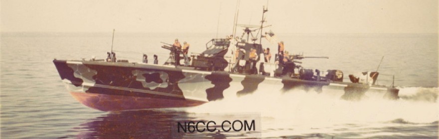
Formerly enlisted, now a “Boot Ensign”, I was initially assigned to CRD-21 Staff as Weapons Officer and Electronic Materiel Officer. I subsequently also served as Executive Officer of PTF-18 and then “fleeted-up” as Officer in Charge of PTF-17 (seen above), a distinct honor, challenge and responsibility for a young Ensign. And fortunate to have landed THE best job in the Navy!! Our great crew trained me and kept me out of trouble – in the finest Navy tradition.
The PTF: The first 80 foot, wood-hulled boats dubbed “Nasty Class PTF’s” by the US Navy were built for the US in Norway, based upon the Norwegian Tjeld Class Motor Torpedo Boats.
The name Nasty came from the first prototype Motor Torpedo Boat in the Norwegian Navy, HNoMS Nasty. That boat was the basis for their later Tjeld class MTB’s (named for a Norwegian sea bird). (Note that the US Navy PTF’s were NOT Tjeld Class boats nor were they called that).
It is interesting that Admiral Arleigh Burke, then Chief of Naval Operations, was given a tour of HNoMS Nasty in Norway in May 1960. He apparently liked what he saw.
The Norwegians had learned from the WWII PT boat experiences of all combatants and built upon them – unfortunately we did not. We gave up on this type of vessel after WWII when most surviving Pacific boats were burned on the beach at Samar in the Philippines. They Were Expendable….The next time it would be a “push button war”.
Then the North Vietnamese communists invaded South Vietnam just as the North Korean communists invaded South Korea in 1950. That memory was still very fresh in the early 1960’s.
PTF-17 Underway N6CC
As part of our response in defending South Vietnam, we bought 14 boats from Norway (PTF’s 3-16). That hybrid, convoluted type-name “PTF” or “Fast Patrol Torpedo Boat”, had actually surfaced for 2 post-WW2 boats, PT-810 and 811 but later re-designated as PTF’s 1 and 2. These were 2 experimental, gasoline powered, aluminum-hulled boats pressed into service in December 1962 for SEAL support and training.
With no enemy targets approved for (or worthy of) a torpedo, the US Navy outfitted them as heavily armed gunboats, not unlike the WWII PT boats used to take THAT fight back to Japan, especially in the New Guinea campaign. Despite the name PTF, no torpedo’s were mounted on the US boats.
Below is a photo of PTF-3, the first U.S. Navy Nasty boat, here aboard Open Lighter YC-1410 in the Philadelphia Naval Shipyard on 27 December 1962. Note the hook, lifting slings and spreader bars are present, either for onloading or off loading from the barge. Special thanks to Gaute Morland for finding the photo; see his Comment in the discussions below.
I do not know how the boats were transported here from Norway but clearly not aboard a small 110 foot barge like this one crossing the North Atlantic. That was most likely as cargo on a larger ship such as an LPD and then subsequently off to WestPac.
The USS Denver, LPD-9 did transport PTF’s in her well deck between Da Nang and Subic Bay during the Vietnam war although many boats made that transit on their own.

PTF-3 on barge in Philadelphia 1962 Official U.S. Navy photograph
Note the absence of guns but the original torpedo launcher mounts were still fitted fore and aft.
After the first 14 Norwegian Nasty’s entered USN service we subsequently built another 6 wood-hulled PTF’s (PTF-17, 18, 19, 20, 21 and 22) as virtual copies under license to fulfill the needs in Vietnam.
Incidentally, PTF’s 1 and 2 actually served briefly in Vietnam as a stopgap measure but they were worn out and unreliable by then and then withdrawn.
Note that the US term “PTF” predated the Norwegian/US boats. The Norwegians called theirs Motor Torpedo Boats a term commonly used in WW2.
The differences between the Norwegian and the Trumpy-built boats were few. These included the radars and radar antennas (Decca versus Karr), the diesel generators (Perkins versus Onan) and a difference in the tank room configuration. There were differences in the Engineering Main Control configuration as well as in the communications systems.
Those 6 were built by John Trumpy and Sons in Annapolis MD in 1967-68 and are sometimes called “Trumpy’s” or sometimes “PTF-17 Class” or sometimes “Nasty’s”, depending upon the document. PTF-17 was launched on 11/17/67 after a 7 month construction effort. She was delivered to the US Navy on 7/1/68 after fitting out.
Note that these combat craft were not Commissioned US Navy ships and hence were not designated as the “USS PTF-xx” a common error/misconception.
CRD 21’s Boats: Some Background: The boats of Coastal River Division 21, PTF’s 17, 18 and 19 operated in Vietnam for several years.
There are several photos elsewhere on the web of Da Nang harbor and the PTF base piers during the late 1960’s – early 1970’s. The boats pictured are clearly Trumpy’s as indicated by the distinctive rectangular slot radar antennas. (PTF’s 3-16 had a prominent curved radar antenna described elsewhere on this website). The Da Nang photos show boats that could have been any of PTF’s 17-22 but the photo’s don’t show the specific hull numbers. PTF’s operating in North Vietnamese waters were unmarked.
There is another photo of Trumpy’s taken at Cam Ranh Bay where the boats spent a few days “laying low” as part of a psyops “plausable deniability” effort.
There are also numerous photos of PTF’s being repaired and overhauled back at Subic, including one described as PTF-17 getting some damaged planking repaired. Again, many Trumpy’s but no obvious individual hull numbers are visible. The declassified record is pretty thin when it comes to combat ops of individual boats by hull number; that sort of detail did not make it in the overall operations summaries. Hopefully more will be revealed over time, especially by the actual participants.
Hanoi’s February 1968 Tet offensive in South Vietnam was a tactical disaster for them when the people of South Vietnam didn’t “rise up” against the government as hoped. Despite their tactical surprise the Viet Cong and many North Vietnamese Army elements involved in the South were essentially destroyed. But they achieved their strategic objective of further turning “useful fools” (V. Lenin) in the American public against further combat to defend the South.
That bought the NVA time to rebuild their forces in the South. So among other actions, in November 1968 the President ordered the cessation of PTF PLOWMAN Ops against enemy forces north of the 17th parallel (however some PTF Ops were then conducted in the South). In 1969, COMUSMACV recommended to the Joint Chiefs of Staff that PTF’s 17-22 be pulled back and held in reserve at Subic Bay, believing that the existing 7 Nasty’s at DaNang could handle scaled-back taskings.
During that time frame some OPLAN 34A maritime ops were being cut back due to transfer of responsibilities to the RVN forces but also as an economy of forces savings. The JCS did not act upon the recommendation regarding the 17-22 boats. It appears that some of them were deployed along with the remaining PTF’s to make up for losses, mostly night time groundings in poorly-charted North Vietnamese waters. (Reference 7, MACV-SOG Maritime Ops Summary, 1970).
The 4 Osprey aluminum hulled PTF’s (23, 24, 25 and 26) were previously withdrawn from DaNang in 1968 after only 6 months of operations – their aluminum hulls suffering severe fatigue cracking. Those 4 were replaced by at least 4 of the Trumpy boats that had been built earlier (Ref. 34).
But things heated back up in early 1971 with several successful PTF raids north of the DMZ which shot up or sank numerous North Vietnamese gunboats, torpedo boats and supply boats.
With the pending disestablishment of MACV-SOG in 1972 and the ending of the RVN leasing arrangement, the PTF’s were redeployed back to the US and assigned to the Coastal River Squadrons and Divisions, formerly called Boat Support Units prior to June 1971. I cannot find a solid reference to when the boats actually moved back to the US or how they were transported. That was likely done as cargo aboard an LSD or similar ship. It is known that PTF-26 was transported back as deck cargo aboard the USS Tuscaloosa, LST 1187.
CRD-21’s 3 boats were sent to the Naval Amphibious Base (NAB) at Little Creek VA and at least PTF-17 did some exercise work (Exotic Dancer series) in the Atlantic in 1972 before they went to CRD21 at Great Lakes in October 1972. (and no, they were not used to “train recruits” at the Great Lakes boot camp as a couple of Keyboard Kommando’s have proclaimed online.) PTF’s 20, 21 and 22 were assigned to CRS 2 at NAB Coronado for Pacific Fleet ops.
Below are some photos of PTF-17 operating in the Atlantic circa early 1972. This was possibly in conjunction with the Exotic Dancer fleet training exercises off the Virginia Capes or training workups out of Guantanamo Bay Cuba. When the PTF’s were not performing training missions or supporting SEAL teams, they were often utilized in Fleet Training Exercises to simulate Soviet OSA or Komar missile patrol boats in running long range approaches against other exercise units.
The following 3 photos courtesy of GMGC(SW) Rob Summerhill USN who was a Gunners Mate aboard the USS Joseph Hewes DE 1078 at the time. See the Comments section below. Thanks Chief!

PTF-17 Exotic Dancer Lant Fleet
The above shot through a telephoto lens at a distance.

PTF-17 Approaching
PTF-17 approaching the USS Hewes out in the Atlantic.

PTF-17 coming alongside the USS Hewes during Exotic Dancer exercise.
PTF-17 coming alongside the port quarter of the USS Hewes for a post-exercise debrief at-sea with the crew. I have found no information indicating that PTF-18 or 19 were also involved in these exercises. They were both PTF-17 “Classmates” and all 3 boats were at NAB Little Creek at the time before deploying to Great Lakes.
I cannot find any definitive official references to the dispositions of the remaining Nasty boats (hulls 3-16 minus the operational or combat groundings) but most if not all ended up at Little Creek VA. The 3 CRD21 boats made the transit from NAB Little Creek to Great Lakes via the Hudson River, the Erie Canal system and Lakes Erie, Huron and Michigan. Can any of you Coastal River Squadron Two guys provide any detail here?

PTF-17 Model
Above: A nicely detailed mahogany 1/48 scale model of PTF-17 along with some representative ammo. This model was built from “scratch” by a shipyard worker at Peterson Boat Builders in Sturgeon Bay Wisconsin in late 1974. He built it from scrap mahogany utilizing detailed measurements he made of the actual boat while it was in winter overhaul at the boat yard. The hull is a single, solid piece. He came aboard with calipers, rulers and a clipboard, documenting all measurements. He even used some of the Marine 123 green and red anti-fouling bottom paint to get the colors exactly right. Glass case cover removed.
Representative ammunition in the case: 40 mm “Bofors” automatic cannon high explosives round, 20 mm high explosives round, .50 caliber M2 BMG, 7.62 mm M-60 machine gun belted rounds. We also carried M-16’s, M-79 grenade launchers, M-870 shotguns, .45 automatics and a .38 cal revolver. Oh, and the 81 mm mortar on the bow. See the “PTF Firepower” category in this blog for further weapons details.

PTF-17 Model
Another view. The boat builders at Peterson did outstanding work; their specialty was wooden boats. They also built many mine sweepers, patrol boats, tug boats, sub chasers and landing craft for WWII. They were building wood minesweepers for the Republic of Korea and aluminum hulled 65 foot US Navy patrol boats while we were there in overhaul. True craftsmen. It was amazing to watch them steam-bend long mahogany hull planks with compound curves that then fit precisely into the hull of our PTF’s.
Surviving PTF‘s: (to my knowledge as of April 2018)
PTF-3 (the first Nasty) is at 29 degrees 3.435 N x 81 degrees 17.29′ W (Deland FL)
PTF-10 (reportedly) was at 36 degrees 45.30N x 76 degrees 18.15W in a November 2016 Google Earth photo (Chesapeake Yachts VA)
PTF-17 (the first Trumpy) is now located at 42 degrees 52.653′ N x 78 degrees 52.801’W (Buffalo NY)
PTF-19 is located at 39 degrees 16.447 N x 76 degrees 10.081 W (at Worton Creek Marina near Worton MD)
PTF-25 Although not a “survivor” the wreck is located at 35 degrees 1.90 N x 76 degrees 27.85W (in the MCAS Cherry Point NC gunnery range BT-11)
PTF-26 had been moored at 38 Degrees 8.98 N x 121 degrees 40.99 W (near Rio Vista CA. See earlier Google Earth photos). In May 2023 she moored in Morro Bay CA, apparently headed for Kentucky eventually under new ownership. See below.
PTF-23 (the first Osprey) has been heavily modified structurally, including small 12V71 Detroit diesels, modified deck house and the addition of a small crane. It is back east as the Research Vessel “Osprey” Completely unrecognizeable as a PTF from the deck up – but it’s afloat.
In May 2018 it appeared for sale in Boats and Harbors for $225K, presently located in Port Canaveral FL.
PTF-26 (the last Osprey) was operational in the San Francisco Bay area, based in Rio Vista CA with the Liberty Maritime Museum. PTF-26 has been modified with 16-V71 Detroit diesels replacing the Napier Deltic’s and some superstructure modifications including added windows in the CIC area and the inclusion of a small deck house aft. It is otherwise complete, in good shape – it even had a 40 mm “Bofors” gun back aft.
The rest of the boats are gone, lost to accidental or combat groundings, missile and gunnery tests or the scrappers. “Excessed” by the Navy in the late 1970’s, seven “east coast” wooden boats ended up rotting on the sand for 15 years at Great Bridge VA. A Google Earth photo taken in April 2002 showed 7 PTF’s on the beach, in a photo taken a year later, they were gone (36 43.570’N 76 15.048’W). One apparently went to the UK; then most off to a local marina (Chesapeake Yachts) for scrapping.
Incidentally, the disposition and provenance of the boats once they left US Navy service is very fuzzy due mainly to poor identification markings on the specific, surviving boats. Once the hull numbers had been sanded off the bridge and overpainted there was little else to definitively identify any particular boat. The defining engraved stainless steel identification plates bolted to the aft bridge bulkhead (at least on the 17, 18 and 19 boats) were lost to souvenir thefts. Some equipment and fittings had apparently been marked with an associated hull number but yard work at Subic Bay and DaNang during the war found many parts being swapped during repairs, temporary cannibalizations and overhauls. “Get her back in the fight!”
More on that later. I can positively identify PTF’s 17, 18 and 19 due to unique repairs but the identity of the rest of the boats is buried in history someplace. The website ptfnasty.com has lots of information, speculation, observations and photos of the the boats while on the East Coast, after the US Navy disposed of them.
Below is a shot of PTF-18 up on step. Authors Photo:

PTF’s 23-26 were different boats entirely – the “Osprey” class built by Sewart Seacraft in Berwick, Louisiana in 1968. They were 95 foot aluminum hulled boats but with the same Napier Deltic engines and weapons systems. They were too big and heavy (at 105 tons) to really get up “on step” and cruised more as a “semi-displacement” patrol boat type hull would despite the same engines.
They were therefore slower – by 5 knots – than the planning-hull Nasty’s according to Reference (9); Jane’s Fighting Ships and Reference (17); PT Boats at War . No where near being “clocked at 51 knots” as one anecdotal claim has it, or even 41 knots. But they were tried. Sadly, 2 of the 4 were sunk as targets: MCAS Cherry Point NC and Pt Mugu.
There are anecdotes stating the Osprey’s were originally built to be powered by a gas turbine engine – hence the huge air intake structure behind the pilot house. (It’s also possible that only one Osprey was to be turbine powered, however they all have that large air intake structure. More research needed here.)
That would have been a great system for a boat that size although at the expense of fuel economy. With all that aluminum they also had a much bigger radar return too, not good for stealthy Ops or when up against radar-controlled guns.
Reference (7) states all 4 Osprey’s were briefly in Da Nang in 1968. However, they were withdrawn back to the US within 6 months because their aluminum hulls developed severe fatigue cracks from the pounding in the open sea. Can any of you Osprey – MST/BSU vets who were there expound upon any of this?

PTF-26 in Oct 2010
Above a nice shot of PTF-26 off the Golden Gate, San Francisco during Fleet Week, October 2010. Taken from the S.S. Jerimiah O’Brien Liberty ship. Note that the owners (Liberty Maritime Museum) have applied a camouflage pattern based on the WWII Elco Boat.
PTF-17 had a unique camouflage adaptation during the brief time that scheme was experimented with back at Great Lakes. (Interestingly, the owners of PTF-3 seemed to have duplicated the PTF-17 design and colors during the PTF-3 restoration back in Florida).
There are no known published photos of any of the PTF’s with pattern-camouflage during the Vietnam war – they were painted Marine Formula 123 Lustreless Green. But the 26 boat sure looks great out there – and OPERATING!! The last of the PTF’s. Thanks to Liberty Maritime for setting me straight on the PTF-26 camo design. Photo by Jason Atkin.
Below is PTF-26 in Morro Bay CA in May 2023. She has been there for some time awaiting transport to her new owners who intend to operate her on the Ohio River out of Paducah Kentucky. She was to be transported by a heavy-lift vessel via Panama but that deal apparently stalled for some reason. She currently sports a Kentucky registration number however.

PTF-26 May 2023
Above: Note the aft gun ring that formerly mounted the 40 mm Bofors auto cannon. I understand* that gun was given to the USS Lucid MSO restoration as it was not permitted to be aboard while transiting the Panama Canal. (*Chow Hall Intel).

PTF-26 in Morro Bay CA 5-23
Welcome Aboard: This article will describe life aboard PTF-17 and Coastal River Division 21. I’ll note the very minor differences between the Norwegian and Trumpy PTF’s, and point to references about their Vietnam combat Ops to the extent that some of this information is now being declassified. I was still in Navy schools / training when most of that effort was ongoing.
CRD-21 certainly wasn’t Vietnam, the Canadians were very friendly, but there we were, sometimes freezing, roaring around the Great Lakes of all places. That was our new, post-Vietnam mission; training to support future NATO ops in northern Europe. As a Division of the east coast Coastal River Squadron 2, the Great Lakes were a good place for us to train for cold weather environments.
Take a tour of PTF-17 as it was assigned to Coastal River Division 21, an element of Coastal River Squadron 2 based in Little Creek VA. See photo’s of main systems, weapons, communications, engineering etc. Included are photo’s of PTF 18 and 19 as well as the Patrol Gunboats Asheville, Crockett and Marathon, PG’s 84, 88 and 89.
Command and Control:: All tactical combat units require the ability to move, shoot and communicate. So let’s start with Comms since command and control is essential to the mission. There is almost no information on the Web describing the communications systems on PTF’s so I will attempt to fill in some of that void. (Since I was also a Ham Radio operator and an electronics engineer, this aspect of the boats was also of particular interest to me.)
“All members of a MTB crew must be qualified in standing a radio watch. Each man must have an operating understanding of the radio equipment, know the Morse Code, understand the effective call sign, and Recognition and Emergency Identification System.” From the WWII “Motor Torpedo Boats Tactical Orders and Doctrine” manual. 1942
Afloat:
PTF-17 had HF, VHF and UHF transceivers to cover most comms needs. (Reference 64.) Our JANAP plain language call sign was Culpepper Sierra 17, quite a mouth full, so we normally used simply “Tango One-Seven”, particularly between the boats. My “personal” call sign was Tango One Seven Actual in keeping with the protocol of the day. The CRD-21 callsign was Richard November, AKA “Two-One”.
The photo below shows the radio room of PTF-17. On the right, top is the HF transceiver ARC-94 (Collins 618T-2). Its control head is behind the white stanchion just above the CW key. Below the ARC-94 is the ARC-27 UHF transceiver – its control head is up on the bridge.
On the operating table we see the SB-315 CW key and to the left of that is the VRC-46/RT-524 VHF transceiver. It is locally tuned and has a C-1138 remote control on the bridge. Above the VRC-46 are the three AM-215/U audio amplifiers. These can select any radio output, amplify it and route it to any speaker or handset. There are also various junction boxes and patch panels in view. A compact, efficient space. This view is looking outboard, forward is to the right.
Authors Photo

PTF-17 Radio Room equipment N6CC
High Frequency Radio: We had an AN/ARC-94, based upon the Collins 618T-2 aircraft transceiver operating from 2-30 MHz which was mounted in an overworked shock mount in the radio room. The radio room was approximately under the port side 20 mm gun mount. This radio provided SSB, CW and AM capability with 400 watts PEP output on SSB but we mainly used SSB. (plus an occasional AM radio check with some surprised CB’er on 27.065 MC – Channel 9).
It drove a Collins 490T automatic antenna matching unit which was mounted on the after bulkhead of the chart room and it was connected to the port side 28 foot fiberglass whip antenna.
Some photo’s of these boats while in Vietnam (and also while on post-launch sea trials on Chesapeake Bay) show the two HF whips mounted forward of the bridge, braced with support struts to the bridge structure. Some time later, on some boats, they were moved further aft to the positions seen in my photo’s.
Also, our fold-down main radio / Nancy Beacon mast seems to have been a later modification. Some Vietnam photo’s don’t show this mast. A photo of a PTF hulk in Great Bridge Virginia also shows the HF whip mounted forward with the support struts.
The HF radio drove an H-169/U handset remote unit on the bridge and its normal aircraft control panel for frequency and mode selection was mounted in the radio room. The radio was powered by the boats’ 28 VDC batteries as well as a big 28V-115V 3 phase 400 cps rotary “inverter” which was located in the weapons locker in the passageway across from the head. The radio could be operated locally in the radio room via an RS-38 Mic plugged directly into the transceiver.
Also interesting, the NAVSHIPS Technical Manual (see Reference (15)) for PTF’s 9-16 (the last 8 Norwegian boats) shows the below photo of a Collins TCS AM and CW HF Radio set, generally in the same location in the Radio Room and notes this radio was installed equipment.
The photo also shows the TCS Loading Coil, required for use with a 28 foot whip on the lower frequencies. It appears that the TCS’s were aboard the 9-16 boats while in Vietnam as the primary HF radio at least at some point. Interesting, considering that the same Collins TCS was the primary radio system used in the WWII PT boats.

Radio Room TCS Set, Nasty Class PTF
At some point prior to 1966, the ARC-94 SSB/CW radio was being used on some, if not all of the Nasty Class boats. It was noted that maintaining the ARC-94 was problematic due to the severe mechanical shocks they encountered while underway. Repair work was difficult on these complex aircraft radios due to repair parts logistics and the lack of specific training by NAD personnel on these particular sets.
A recommendation was made to either improve the ARC-94 shock mounts or install (re-install?) the WWII vintage TCS sets as a replacement! (Reference (33). I cannot determine if this was ever done on all, or any particular Nasty boats.
The NAVSHIPS Technical Manual for the PTF-17 Class also shows the CW-only AN/GRC-109 as standard, installed equipment (but not its location on the boat.)
Curiously, the GRC-109 transmitters were not directly connected to an antenna on CRD-21’s boats as we received them, even though the PTF’s had a second 28 foot whip on the starboard side of the bridge. All Nasty and Trumpy Class PTF’s (and the Osprey’s) had two HF antennas and it is highly likely the starboard antenna was dedicated for the GRC-109’s.
There was no provision for any starboard antenna matching and in fact, I recall that the receivers and AC power supplies were missing when we received the boats. The transmitter on PTF-18 was bolted to the radio room forward bulkhead, about eye level and there was an SB-315A/U CW key located on the operating desktop next to the VRC-46.
Since the ’109 was not essential, operative or even complete on PTF-18, I initiated a request to Division and Squadron for a BOATALT (boat alteration) to remove them. As the Staff Electronics Materiel Officer for CRD21 (collateral duty) I was responsible for making sure all the shore and afloat equipment was working and supported properly.
It was approved and they were excessed; one less mystery problem to deal with but we never received a modern replacement for them. (If someone can get aboard PTF-17 at the Servicemen’s Museum in Buffalo, please take a picture* of the forward bulkhead and note the position of the GRC-109 mounting holes – I’d appreciate it!). More details on the AN/GRC-109 sets here: AN/GRC-109
- UPDATE 8/30/22: The Staff at the Buffalo museum sent me a photo of the forward bulkhead of PTF-17 showing there are NO bolt holes for mounting a GRC-109 there. PTF-18 certainly had its radio mounted there (I was the XO at the time). So it seems that the GRC-109’s noted in the NAVSHIPS document many have been “informally” installed elsewhere, at least on PTF-17. The mystery deepens.
The CW key for the ARC-94 or the GRC-109 could be “patched in” via the two gray junction boxes mounted above the key. The ARC-94 radio was capable of operating CW via the Mode switch on the control panel. Our Radiomen in the crews were all CW qualified in those days, unlike today.
Most of our comms were tactical, boat-to-boat FM voice. Long range comms back to base were another matter; that was normally SSB voice. The built-in CW key mounted on the GRC-109 transmitter would have been barely usable with the transmitter being mounted vertically on a bulkhead, at eye- level. The transmitter has provision for an external key which would have been much more practical in that installation. There is a NAVSHIPS drawing (in addition to the basic equipment list) that details each communications system, including the GRC-109 but they are in the National Archives; I have not seen them. More research needed.
During the war, the GRC-109 was relied upon for comms back to Base or “elsewhere” during raids in their operating areas. Ref (7) indicates they used the following freqs for CW with the GRC-109 (incorrectly identified as the CIA’s nearly-identical “RS-1” in the document): Transmit/Receive: 4069.3/8217, 4258/4632, 6220/3493 KC as primary, secondary and tertiary circuits respectively. Split T/R operation would have been routine and its likely the Ops officers/OinC’s had authority to pick the best freqs for day/night operations, the “hot work” happening mainly at night.
Reference (33) states that there were severe logistics issues in obtaining additional crystals for these sets despite many special request follow-ups. A trip to “Radio Row” in New York could have quickly produced barrels of FT-243 crystals being bought back from the surplus dealers of the day. I remember seeing 55 gallon drums of FT-243’s for 25 cents apiece in those days. Finding suitable frequencies would have been pretty simple….JAN, Texas Crystals, Peterson, ICM and a host of others were still selling FT-243’s to any frequency you wanted for a few dollars. Huh?
The use of those “split Frequency” assignments ruled out the ARC-94 as a possible CW radio on the PTF’s, at least in split frequency operation. It is incapable of operating on separate transmit and receive frequencies. I believe this is good evidence that the GRC-109 (and by implication the TCS radio on the older boats) was the primary long-range radio set used on these missions. However, during the 8 war years of PTF operations with different classes of boats delivered and/or modified at different times, almost any configuration was possible.
A 28 foot whip would be resonant around 8.3 MC. However with its feedline and ground line to the bronze ground plate along the keel, in a wood hull, the resonant frequency would be somewhat lower. The 4 and 6 MC transmit freqs would have seen a capacitive load without any matching devices; the receivers would have worked fine.
They probably just tuned up and let the ’109 grunt out CW. I’ll have to try that setup with mine to see how they handle it. While aboard PTF-17 I did run my Heathkit SB-102 SSB Transceiver into the starboard whip without a tuner on 40 meters Ham frequencies and it worked great, I’m sure the GRC-109′s did the job, mine always does.
Here’s a shot of the Heathkit SB-102 SSB transceiver aboard PTF-17 during a Ham Radio Field Day back then, probably 1975. The starboard HF whip antenna is visible outside the bridge window. 
Back to the ARC-94′s. We used the HF radios on occasion, particularly when we were underway around the Great Lakes on various training and recruiting port visits. We had several HF freqs available but mostly used 6970 KC USB which covered the ranges of interest. They had no squelch so they were a bit annoying being turned up to overcome the formidable engine noise when at-speed.
One day the USS Marathon ran into a problem while transiting the St Lawrence Seaway, inbound to Great Lakes from Guam. They called us on 6970 KC’s, we had good comms and got them the assistance they needed. This was before Cell Phones don’tchya know!
Reference (7) states that HF SSB radios, UHF radios, IFF gear, galley equipment etc (being “U.S. attributable”) and the forward 40 mm gun mount were removed from the Norwegian Nasty boats (Hulls 3-16 inclusive) at Subic prior to commencing Ops in 1964. Again, Reference (7) has noted later on the availablity of SSB voice (for the ARC-94, misidentified in Ref (7) as the “GRC-94″) and assigned SSB freq’s in combat aboard the PTF’s but it appears it was not used for voice comms. (Reference (32)). (Conflicting references, more research is needed here but the unclassified record is pretty vague and it contains several typo’s and other mistakes.)
It is possible that the ARC-94 SSB radios were only briefly in the Nasty hulls but they were installed in the Trumpy’s from the very beginning. However, I have learned that the ARC-94 was routinely used on offline – encrypted CW circuits (possibly from the Nasty Class) to send hourly SITREPS while on PLOWMAN missions, at least in the 1969-70 timeframe. (Reference 32)
During covert intel ops, psyops and full-on raids, HF AM or SSB would have been too easy to intercept; no crypto capability, using a complex and therefore a possibly less-than-reliable radio system. The intercept problem would have been serious since the boats primarily operated with local crews who spoke the same language so it would have been easy to perform COMMINT against them.
Encrypted CW would have been more secure. The operating areas were around 200-250 miles over sea water from Base, so a TCS set or a 10 watt GRC-109 sending coded CW would do the job pretty reliably. A 400 Watt ARC-94 would have been an even easier shot when necessary. I wonder what the tropical static noise sounded like with all that lightning around.
Incidentally, our HF comms aboard were very quiet. Although each engine had 18 cylinders and 36 pistons, they were diesels – no ignition noise! Fluorescent lighting was quiet and mostly brushless motors in the aux gear. It made for a very quiet RF environment.
VHF: On VHF we relied upon the trusty AN/VRC-46/RT-524 FM radio also mounted in the Radio Room. It covered 30-75 MC with output of around 35 watts into the AS-1729/VRC whip antenna. We used the VRC-46 for 90% of our Comms as it was reliable and had SQUELCH! The whip was originally mounted on the forward starboard side of the bridge and the radio used a C-1138 remote control box with H-189/U handset on the bridge. A great radio system that could handle the pounding that often caused the other radios to fail.
Our primary freq was 39.00 MC. Apparently that freq was also common to US Army armor units at Ft Knox, infantry units at Bragg and other Army units in the country because we often talked with them when “skip” propagation was in. Pretty reliable, pretty often. We talked with guys in tanks, APC’s, CP’s and even some PRC-25′s being humped around. We also worked an Army helo once – indicated by rotor blade modulation of his signal. We’d ask “how’s the chow”, they wanted to know “how’s the fishing”….
When we got back in, we could look up their daily callsign and find out who/where they were. You could always tell when you were talking to a VRC-46 – the cooling blower and HV switching supply for the output tube had a distinct, loud background whine. The Russian REK (Radioelectronic Kombat) guys would have had a field day with us…
We also carried a PRC-25 (or was it a 77?). Our SEAL team used it when going ashore on training exercises in their IBS, Inflatable Boat Small. Great radio, always worked.
I remember when the message came in directing all PRC-25 owners to install the battery vent device in the side of the battery boxes. Apparently the new BA-4386 magnesium batteries out gassed hydrogen and some cigar-smoking RTO probably blew himself up with one. I believe that message was actually the first directive establishing The Great Nanny-State we presently find ourselves in.
The VRC-46 system worked well but as stated earlier, it was not quite enough to make it from our gunnery training areas back to base. I experimented by installing another AS-1729 whip on the top of our foldable mast, getting it somewhat higher and more in the clear. It made about a 15% improvement in range so I submitted a BOATALT request up the chain and got it approved for the PTF’s.
UHF: We had an AN/ARC-27 aircraft radio, a very heavy 1950′s beast that we used to talk with aircraft and occasionally each other. The antenna was the Navy standard AS-390 “spider” up on the fold-over mast. H-169/U handset and a small Channel Select panel up on the bridge. The ARC-27 in the Radio Room would wear out the overworked shock mounts on a regular basis and then fail. We had a deal with the Naval Air Station at Glenview Illinois to provide us repair support as that was still a common radio in Mil aircraft as was the ARC-94. They’d fix our gear, we would take them for rides.
As noted above, much US-supplied equipment was removed from the Nasty boats before they were leased to the RVN navy for non-attribution purposes. However shortly after they arrived in Vietnam, ARC-27 UHF radios were installed on the PTF’s at DaNang in order to coordinate air cover with RVN Air Force A1H Skyraiders.
We also talked with NAS Glenview’s P-3 Orions of VP-60 as they “searched for subs” in the deeper sections of the Lakes, on their way out to the Atlantic to track the real Russian subs operating off our coast. The P-3’s used to like sneaking up on us from astern, blasting by us at low altitude when we were underway. They left a big wake in the water from those 4 big turboprops. The lookouts spotted them long before, so we were ready. Hitting them with the morse letter “G” from the signal lights, the standard exercise surrogate for Gunfire; they buzzed off, probably not knowing morse code or surface warfare training trivia. Ha Ha, we got ya – BS! We got you…
We did a fair amount of search and rescue training with the US Coast Guard units at Chicago. They flew HH-52A Helo’s and we did many underway transfers of simulated litter patients, usually simulated by a case of beer wrapped inside a kapok life jacket lashed to a stokes stretcher.
We quickly learned the “helo static electricity grounding stick trick”. Grabbing a stokes stretcher hung by a steel cable from a helo while standing on the aluminum soft-patch over the engine room provided quite a static electricity jolt! Build a whack-stick from a piece of pipe, ground wire to the deck plate and whack the stretcher BEFORE you touched it – helo rotors could build up a lotta volts… Authors Photo Below:

Fun Fact: The UHF radio came in handy one day while we were firing 81 mm mortar illumination flares and the .50 Cal in a daytime training exercise. A lookout reported incoming aircraft (CEASE FIRE!) and soon a TWA 727 jet buzzed us about 2000 feet above the water in a hard left bank. The firing area was in the south-center part of the lake and was apparently under a VOR path into O’Hare airport. The pilot apparently thought we were in distress by seeing all the flares, he was still too far away to see the .50 Cal TRACERS! So I figured I would call him on the UHF Guard freq of 243.0 MC. Even civilian aircraft guard that freq, right?
Wrong, but the control tower at Naval Air Station Glenview did and replied, asking why Navy PT Boat-17 was calling unknown TWA 727 in the Lake Michigan Controlled Firing Area on the aircraft emergency frequency. (A reasonable question.) I explained the situation to him, he got on the O’Hare tower freq and called off the 727. Probably a rare occasion for an airliner pilot to buzz a PT boat. He was probably an Air Force Reserve C-130 zoomie on drill weekends. Commence firing.
We also had a PRC-41 UHF manpack. Used it to talk with the Helo’s occasionally but rarely carried it. I think we got it from salvage along with the batteries and charger. Comshaw….
Here’s another shot of underway Air Ops with the Coast Guard. Standard Air Ops procedure was to pick a course (assuming you had clear navigation) to put the relative wind 30 degrees off the port bow at about 20 knots. This allowed the helo to fly directly into the relative wind and permit the pilot to see what’s going on. (Helo pilots usually sit in the right-hand seat unlike in fixed wing aircraft). This also allowed the winch operator to get a good view of the situation. They look like they are “crabbing” into the wind but they are not. authors Photo

Marine Band VHF: We carried a Raytheon RAY-50 on the bridge for talking with the many civilian boats in the area. Particularly in the FIRING AREA. These people were clueless, having never read a Notice To Mariners requiring them to stay clear of this charted location. (Come to think of it, that TWA pilot probably didn’t read the Notice to Airmen that we also routinely sent out. But I’m glad he looked anyway).
We would also use the RAY-50 to talk with the Locks operator on the Chicago River when we needed to clear the locks, occasional drawbridge operators and particularly iron ore and grain boats plying the Great Lakes. These guys would travel to/from Chicago right through the firing area and would rarely answer a call on Channel 16 or 13 (bridge-to-bridge).
We’d pull up alongside and hit the horn to chase them away and if anyone even appeared on the bridge wing, they’d just shrug and keep going. Time is money ya know and I gotta get back to the Poker game! Sheesh!
Other Electronics: The PTF’s had a gyro compass, a Mark 27 Mod O as I recall. Pretty reliable but it would “tumble” if we pounded down off some big waves. (back to the magnetic compass). A gyro repeater was on the bridge and it was also sync’d to the main radar and radar remote on the bridge. Good gear.
We carried a Canadian Marconi LN-66 radar as well. Very reliable and could spot a DIW PT boat about 4 miles out, much further if it was as speed because the rooster tail in the wake showed up more than the boat did. We could see a PG gunboat at about10 miles. We also had a fathometer (couldn’t detect fish) and a pit sword for speed indication read out by cool Nixie Tubes.
Fun Fact: In 1974 the line of zero degrees of magnetic variation ran down the west side of Lake Michigan. Also, when the guns were locked down in their cruise positions, the wood hull of the boat did not influence the magnetic compass. Therefore True north and Magnetic north were in the same direction; the gyro and magnetic compass read the same. No need to use the old Navigators memory trick: True Virgins Make Dull Company At Weddings. If you were ever a Navy navigator, you know what that means.
Fun Fact: It’s easy to tell a Norwegian – built PTF from a Trumpy boat at a distance. The Trumpy LN-66 radar antenna was a straight, rectangular “slotted waveguide” antenna. The Norwegian Nasty’s had a Decca radar with a prominently curved reflector-horn antenna *. Also, any PTF photo showing a 40 mm gun mounted on the bow is a Norwegian-built boat – the Trumpy’s always had the 81mm Mortar/Browning M2 .50 Cal machine gun combo on the bow. After arrival in theater the Norwegian boats also had the 81/50 weapon on the bow as a replacement for their 40 mm guns. Positive visual ID features.
(* There is a photo identified in Reference (17) as PTF-13 (Norwegian -built) with some experimental guns installed. It sports the straight LN-66 Radar antenna versus the curved antenna of the Decca radars, the only exception I have found. PTF-13 was apparently kept stateside as a training and a Tech Evaluation boat during the war. The LN-66 radar was apparently being evaluated for future incorporation in the new-construction boats starting with PTF-17.)
ADF: When we got the boats back from Vietnam they had a curious automatic radio direction finder (ADF) system aboard. Very handy off the coast during radar EMCON, when outside NVA artillery range or in making lengthy transits. (we didn’t carry any celestial navigation gear or pubs, although we were qualified).
The rotating loopstick antenna was inside about a 6 inch square, 2 inch thick block mounted on a mast between the bridge and the forward centerline ammo ready service locker. The electronics and readout was in the chart room and it was strange indeed.
It was a US Mil aircraft ADF system of some sort as indicated by the aircraft-type control panel and azimuth display dial. But they were mounted in a metal box, about 1 foot cube, obviously made by an unemployed automotive sheet metal worker at Subic and spray painted (kinda) in haze gray. What a kludge. The metal looked like it was cut with a cold chisel and nothing was square. Also, it didn’t work on any of the boats. Another BOATALT request up the chain and they are gone (but a good ADF system would have been very useful and we never got a replacement system).
The boats also had a NANCY infrared signaling system. It consisted of an incandescent light bulb inside an infrared glass dome filter mounted up on the mast. It is the black-looking hemisphere on the mast in the USCG Helo photo, above. We had an IR Metascope viewer (SAR-7 I recall) so we could see it, the naked eye could not. The light was controlled by a box to the helmsman’s left on the bridge bulkhead, either continuous “on”, pulsating or keyable in morse code with a key depending upon where the function switch was set..
Fun Fact: We would do frequent “cat and mouse” ops, under radar EMCON conditions with the other boats, trying to infiltrate some remote, long coastal area undetected by the other boat(s) that were patrolling it. One night, we were the patrol, PTF-18 was going to try to insert the SEALS in. Earlier that day, I had sauntered over to PTF-18 at the pier, turned their NANCY beacon “ON” in the pulsating mode and then removed the selector switch knob and repositioned it, pointing towards the “OFF” position. We could see them coming miles away – they never figured it out. Some more info on our SEAL Det and training here:
CRD-21 SEAL Detachment
Visual Signaling: In addition to the NANCY system, we had two 8″ signal lights mounted behind the bridge, port and starboard. They were the mechanical shutter type for sending morse code. They had different colored filters, including infrared and could be used as clear searchlights as well. Pretty effective, simple gear – it worked. The light(s) could be removed and our M-60 machine guns mounted in the pintle’s in their place. We also carried a limited Flag Bag, consisting of an Ensign, Jack, Golf (if you were the Guide in formation ops), a 21 Division pennant, Oscar (man overboard) and a Bravo flag for fueling, and gunnery ops.
We carried an early GEN 1 PVS-2 starlight scope with mounts for an M-16 rifle. We also carried an AN/SAR-7 infrared viewing scope for both heat detection and for reading the IR NANCY beacon signals.
Fun Fact: One warm, moonless Saturday night at Zero-Dark-Thirty, we were idling along the beach, darken ship (looking for VC or Spetsnaz infiltrators). Intel had us off Lake Forest Illinois, the home of a fancy liberal arts college – there were probably plenty of enemy sympathizers in the area. Movement! The starlight scope detected much hanky-panky happening among the college students in the bushes along the beach. Until we hit them with the search lights and then hit the engines. Pandemonium! Now, more enemy sympathizers…
Here is an ancient copy of the Underway Check Off list we posted – stuff you needed to do prior to takeoff.


PTF-17 Bridge 1974 N6CC.COM
The Front Office: Above is a shot of the Bridge. Above the dashboard is the pelorus for taking bearings. Underneath, left to right: Windshield wiper switch, Gyro-compass repeater, VRC-46 speaker, pit log (Knot-Ometer), C-1138 remote control for the VRC-46.
On the panel, left to right: Helm (hydraulic steering), magnetic compass, engine RPM indicators, rudder-angle indicator, throttle/transmission levers, engine warning lights, fire detection warning lights, navigation lights switchboard, cease fire horn buttons for 4 main weapons, and LN-66 radar repeater.
Along the vertical bulkhead are 2 weather tight H-169/U handset holders (HF and UHF usually patched to them) and a small door hiding the ARC-27 UHF radio control box. The sound powered phones were usually worn by the OOD but sometimes the helmsman depending upon the evolution. Off to the right out of the photo are the depth indicator, General Quarters and Collision Alarm switches.
Behind the bridge crew are 2 weatherproof speakers for the radios (loud!). The Ray 50 VHF Marine Band radio was mounted behind the watertight door down to CIC but the door was kept open while underway. Authors Photo
Hull / Overall Design:
As stated earlier, the hull of PTF-17, like the Norwegian boats was made of wood, 7 different kinds I was told. Oak keel, mahogany planking, ash frames, elm stringers, douglas fir plywood decks etc. The Trumpy-built boats were built in the US but the keels and stem assemblies were apparently imported from Norway as part of the licensing deal.
The boats were 80 feet long with a 24 foot beam, 6 feet wider (but the same length) than the WWII Elco boats. This permitted the installation of more weapons, equipment and crew, and especially to contain ten 600 gallon diesel fuel tanks amidships. This was a “planning hull” and above about 25 knots or so, the entire sides from the chine to the rub rail and the entire transom were dry. Above 30 knots, the Bull Nose would drop and you were cooking.
The bad news was that broad beam made operation in rough water pretty tough as it would not slice down through the waves like a narrower hull would. We came down so hard sometimes the shock would trip circuit breakers on the main switchboard OFF as the breaker handles kept going down but the boat didn’t. It was also tough on legs, knees and ankles at times. It wasn’t the North Atlantic but Lake Michigan had some very rough weather with big waves but since the fetch was relatively short, the wave period was fast (they were close together).
You didn’t go up and down on swells, you tended to crash through them. As a consequence, of the several hundred photo’s I took at CRD21, I have very few of PTF’s at-speed; you were trying too hard just to hang on and holding a camera steady (or keeping it dry) wasn’t going to happen.
The Great Lakes supposedly has the highest number of shipwrecks per square mile than any other body of water on earth – I believe it. Lake Michigan alone has over 3000 shipwrecks of substantial size plus innumerable smaller pleasure craft. The 730 foot Edmund Fitzgerald ore freighter encountered such weather in Lake Superior and disappeared and sank without a trace or even a distress call.
Another Great Lakes hazard to navigation were “deadheads”. These were telephone poles or other large caliber wooden pilings that a zillion docks, quay walls and dolphin mooring posts were made of. During the winter ice-over, the ice would grab the poles and when the lake rose (due to a low-pressure weather system moving in), it took the piling up a few inches with it. After awhile they worked themselves out of the bottom and the ice dragged them off as it shifted around.
Since they were waterlogged at the bottom and bouyant at the top, they floated vertically, often just awash with the surface. You had to keep a sharp lookout for them and they made night ops particularly scary since you could not see them on radar until it was too late.
Hit one of these and you had a big hole below the water line – or no more screws or rudders. Another example that “Eternal Vigilance is the Price of Safety”. Fortunately, none of us ever hit one but there were a few close-calls.
The hulls were “plywood” just like the WWII boats. This is not the 4×8 sheets you get at Home Depot (although the deck and pilot house were made of laminated plywood). The hull was made of 2 layers of narrow mahogany planks, about 6″ wide each. The inner planks were about 45 degrees to the keel, the outer planks roughly parallel to the keel. The outer planks were about 1/2 thick, the inner planks somewhat thicker. There was a waterproof, resilient adhesive coating (not fiberglass as some have reported) between the plank layers and they were screwed to the frames, stringers and fish-plates with stainless steel wood screws. The WWII PT boats had over 400,000 wood screws holding them together. Our boats must have had at least that many. Very strong.
I think the Frames were on 12 or 14″ centers. Light, flexible, strong, hard to build, easy to repair. PTF-17 had several combat-era bullet/shrapnel holes in the hull – the repairs can be seen inside covered with odd wood block patches glued and screwed to the inner planks at various places among the more regular fishplates. The outside holes were probably filled with Bondo or something. The hull planking was removed, replaced and repaired many times during overhaul at Subic during the war years.
Here’s a May, 1967 photo of PTF-17 under construction at John Trumpy and Sons. Naval Photographic Center, Wash DC. From ptfnasty.com website.

I managed to bang into the corner of the steel pier while pulling out of a berth on the Huron River, backing into where it empties into the current of the St Claire River. I scraped about a 24″ long gouge in the outer planking, punching a 6″ hole through the inner planking about 12 inches above the water line. It cracked a hull frame about midway down the port side of the engine room. Oh Crap! Tied back up.
EN2 Carl R. and ETN2 Bill T. screwed a huge piece of available 3/4″ marine plywood damage-control patch over the hole and we were off again. Oh, except they painted it like a big white Band Aid. I deserved it.. See below. (Sailors must be closely watched!)
Point is, easy to screw up but also easy to repair. Our “ships carpenter”, QMC “Barney”, made an expert repair of the frame and both layers of planking when we returned back to base. If you can get aboard PTF-17 in Buffalo, look in the engine room, port side, outboard of the underwater exhaust pipe and check out my handi-work!

PTF damage control “training”
“Nice Pants!” A civilian visitor aboard during our port call. “Why is there a band-aid on your boat?”
One April day we were departing Peterson Boat Builders in Sturgeon Bay Wisconsin after a winter overhaul. It was PTF-18, I was XO at the time. The lake had cleared of ice a few weeks ago (so we thought) and as we zig-zagged (see below) down the canal, alternating engines to keep the speed down. We felt a bump.
Investigating, we discovered we had hit an awash ice floe which knocked about a 6 inch hole in the starboard side below the waterline, just aft of the water tight bulkhead in the lazarette; it was starting to flood. We could have gotten out to the main lake area and hit the gas – getting up on step would have put the hole above the water and the lazarette would have drained itself.
In an abundance of caution, and not wishing to hit any more ice at-speed, we did some basic damage control (in waist-deep ICE COLD WATER), energized the bilge pump and headed back to Sturgeon Bay. Of course, the gas-powered P-250 de-watering pump test-ran fine at the pier, now it wouldn’t start in the freezing cold wind out on the lake.
Radioing ahead, they met us back at the pier with a crane holding a huge concrete clump anchor. As we pulled in, we put some dunnage on the port bow and they lowered the clump. Bow goes down, stern goes up, hole now out of water. A day later, back underway again.
By the way, if you are “restoring” a surplus PTF and it has that repaired damage in the lazarette just below the waterline, you have PTF-18! Similarly, if your PTF has a 8″ patch in the transom directly above and outboard the starboard exhaust pipe, you have PTF-19. The Naval Station LCVP ran into PTF-19 while it was moored. Positive ID here….
Apparently PTF’s-19 and 18 “traded some paint” during an ammunition transfer; shortly before they departed for Little Creek upon decommissioning of CRD-21 in 1976. I remember hearing about it with Chief Barney doing some repairs on the forward “rub rail” on the 19 boat. Again, easy to repair.
We carried about 15-20 crew members at a time when the Reservists were aboard for training; the boats being designed for 4 officers and 20 crew depending upon the mission and weapons requirements. There were 4 racks in the Wardroom and 14 in the crews quarters, accounting for those on watch – “hot bunking” it’s called.
The hull was fairly immune to gross trim changes when loaded with fuel and ammo – it rode about the same when when lightly loaded. It weighed 65 tons dry, about 80 tons when fully loaded, good design accounting for this trim stability with the center of gravity not changing much as we burned fuel. With 6000 gallons of fuel aboard we could go 860 miles at 38 knots, 960 miles at 35 knots or 1050 miles at 20 knots. By way of comparison, a standard highway fuel tanker truck carries 6000 gallons for those volumetrically-challenged folks.
Draft at the screws at 75 tons was 6’10″ and at the bottom of the keel was 3’9″ so you could nose into a beach or mud bank if the bottom dropped off quickly. These were not “PBR” River boats of PCF Swift boats – PTF’s were used in the South China Sea and Tonkin Gulf and the engines were pretty unhappy if you had to idle along in shallow water for very long. With both engines at dead idle (750 RPM) you were doing about 12 knots, much to the angst of the Coast Guard while in “no wake zones”.
The rudders were pretty ineffective at low speeds so you would steer zig-zag with the engines (idle or in neutral) to maintain steerage way at low speeds. With those big 4 foot screws, set wide apart and powered by monster engines, they were otherwise pretty maneuverable at low speed. Going slow in a straight line required “pulsing” both engines, something the engines, transmissions, clutches and engineers didn’t like. Carbon and all that…
The boats would easily make 45 knots when lightly loaded in fresh water, especially if it was really cold outside with cold, (dense) air being sucked in by the big turbo superchargers screaming away. They would be a bit faster in sea water (higher density, more prop-bite, more mass for the prop to accelerate). We rarely went above 40 knots as there was no real need and engines were very expensive – they required overhaul when reaching 20 cumulative hours above 2100 RPM. Overhaul was at still Subic Bay in the PI. More on that later…
FUN FACT: You can visually estimate the speed of one of these boats. In calm water at a typical loading the keel cuts the water just under the 81mm mortar mount when the boat is at 40 knots and under the centerline 81mm ready service locker at 45 knots; more forward when slower. The photo on the front page was taken at around 20 knots, not yet up on step.
Camouflage: While in Vietnam, and as we received them, they were painted in Marine Formula 123 lustreless green. A good general purpose camouflage for “inshore” work.
Not Haze Gray because they routinely operated close to the beach when doing Hot Work. Haze Gray is for TARGETS and other big, fat, slow, gray floating hazards to navigation like destroyers etc…
One commenter at another PTF web site stated that the Naval Training Center “ordered” us to paint the boats in “that hideous camouflage pattern”. Not so! – it was our idea. (The Commander NTC actually wanted us to paint them Haze Gray since that’s what The Real Navy looked like. To him.)
Over the winter overhaul period of 1974-75, I had suggested to Commodore Johnston that we try different Camo schemes to evaluate how effective they were while operating inshore. He enthusiastically agreed so I drew up some sample ideas based upon some WWII patterns. He got the OK from Squadron so off we went.
Great leaders, willing to experiment without fear of offending or upsetting someone. It fit in with our mission – and attitude.
We tried the wavy pattern on PTF-17 placing Haze Gray and flat black waves on top of the Marine 123 on all vertical surfaces. The 18 Boat got Leopard Spots consisting of Haze Gray amoebas with flat black centers, also on top of Marine 123.
The 19 Boat got Razzle Dazzle triangle splinters of Haze Gray with flat black interiors, also on Marine 123. That particular type was NOT to try to look inconspicuous while at-sea.
In all cases, the decks and other horizontal surfaces were kept 123 green. Remember, this is the Green Water Navy, not brown water or blue water….

PTF-17 Experimental Camouflage – 1975
Above: A very blurry port-quarter shot of PTF-17 in early 1975 showing the overall camouflage pattern. Also note the second AS-1729 VHF radio antenna has been installed on top of the main mast to increase range.
Note the portside main engine exhaust and cooling water spewing from the transom exhaust; the main engine exhaust bubbling up from the underwater port. The transom exhaust is effective while the boat is stopped or moving slowly. The much larger underwater port handles the main exhaust at-speed. Note the steam cloud from the port diesel 15 KW electric generator on this cold morning.
To evaluate the camouflage, we did some visibility tests by running close-aboard the beach and viewed from seaward, in different lighting conditions and at differing ranges.
Depending upon the background, the 17 and 18 boats were pretty well hidden, the 19 Boat not so much, as expected. In all cases we were running at slow speed – nothing you could do would hide the big white Rooster Tail in the wake at speed.
We would imagine that while hugging the shoreline the camo would be somewhat effective when viewed by a Mach 1 Fast Mover heading for the Officers Club. Especially if the decks were also camouflaged. Just another “lump”. When painted solid 123 green they were more obvious against a typical shoreline, looking like an odd solid dark shape – out of place.. And what are those muzzle FLASHES !?
The 19 Boat was different with the Razzle Dazzle triangles. With triangle bases offset from structural vertical features, it was a bit difficult to ascertain the “target angle” of the boat you were looking at.
Below: PTF-19, PTF-17 in foreground.

PTF-19 Target Angle Disruptive Pattern Paint Photo courtesy of Curt Froyen
Target Angle is the bearing the PT boat presented towards an enemy, from their perspective. In the above photo it is about 060 degrees. It was meant to confuse gunners or fire control viewers about estimating your exact course: Necessary information for gun laying.
Intended to be confusing for a few critical seconds, it worked pretty well for us and apparently very well in the WWII boats (including large Capital ships) as witnessed by many photos of them sporting a similar design.
Below: PTF-19 alongside. Photo of a photo. Unfortunately I don’t have a photo of PTF-18 with its camouflage paint. Anyone else?

PTF-19 Disruptive Pattern Photo courtesy of Curt Froyen
However, in the end that was too hard to apply and maintain on large capital ships so Razzle Dazzle was dropped in favor of simpler designs during WWII.
We eventually went back to solid Marine 123 green at the end of the experiments and when the paint just wore out after a few months trial. (in Vietnam the boats were green, not camouflage-pattern painted.)
Here’s a shot of the PTF’s on the marine railway after being hoisted by the new synchrolift. They were pulled in the winter for overhaul but primarily to prevent damage from the thick ice that formed in the harbor. When frequent storms blew in, the ice smashed itself into big chunks and those chunks smashed anything they contacted. That’s my 1971 Ford Bronco – still driving it but now it sports a desert camo paint job – seen elsewhere on this site. Authors Photo Below:

Engineering Main Control: The below photo shows the engineers station which was actually in the fuel tank room. He monitored all engineering systems while looking aft through the double-pane window into the engine room.
He had the main engine run-stop switches and a duplicate set of throttle/transmission controls although the boat was always controlled from the bridge.
The port and starboard panels contain the 18 engine cylinder temperature gauges (rectangular gauges) for each engine, the RPM indicators and the other gauges to measure sea-suction water temperature, coolant temperature, lube oil temp and pressure, fuel oil pressure, Vee drive oil pressure and temperature, turbo-supercharger temperature and pressure (up to 19 psi of boost), generator lube oil temperature and pressure and a few other critical things I am forgetting.
The big gauges read main-start compressed air flask pressure. That big white cylinder seen through the window is the port main lube-oil tank. It was loud in Main Control and unbearably loud (more like a FEELING) in the engine room, even with ear plugs covered by mickey-mouse ears.
Note that the Main Control layout in the Norwegian boats (PTF’s 3-16) is somewhat different than the Trumpy’s. A good internal identifier. If you’ve got a Trumpy boat, the main control looks like this (or if your radar antenna is the straight LN-66 design).
Authors Photo:

Engines and Vee Drives:
British Napier Deltic T18-37K diesel marine/locomotive engines. Eighteen opposed-piston cylinders arranged in a compact triangle (Delta) , 3 crankshafts, 36 pistons, turbo supercharged, lightweight aluminum, 3100 horsepower (each), 5384 cubic inch displacement screamers. Two of them. Basically converts #2 diesel into noise, spray and adrenalin …More to follow.
With its origins right after WWII, the Brits outdid themselves with the design of this engine. Herbert Sammons took over as the Chief Engineer on this engine in 1949.
Not for the faint-at-heart! Incredible engineering to produce so much power in such a small volume. There are many sites on the Web describing this engine in detail – check them out, especially Reference 106. Also see the many CADD animations. Suffice to say, there is a lot of hardware flying around inside this powerhouse.

Napier Deltic T18 Engine (artist unknown, Reference 106)
Like all diesel engines, they are thermodynamically most happy and efficient when run at a constant speed as in diesel electric locomotives and ships or as prime movers for generators. These guys idled at about 750-800 RPM. As you accelerated through about 1100 RPM they hit a mechanical resonance which was very ugly and probably damaging – get through there quickly. Above about 1300 RPM they were very smooth. I’ll never forget the sound of them driving that screaming turbo supercharger.
When you shut them down (cut fuel) they sounded briefly like a giant dumpster half full of bowling balls being shaken by King Kong. Then DEAD, HOT quiet. As your hearing tried to recover.
The New York City Fire Department had a water pumper truck “The Super Pumper” in service from 1965-1982. It used a Napier Deltic T18-37K to drive a water pump that could deliver 8800 GPM at 350 PSI. Or 4400 GPM at 700 PSI depending upon valving. It could shoot a BIG stream of water 40 stories straight up to knock down walls if necessary, something lesser trucks could not do. It responded to over 2200 fires but is now in a museum in Bay City Michigan.
PTF-18 had one run away while moored in Port Huron Michigan. Apparently the bearing seal in the turbo became worn or failed during start-up and the engine began to suck lube oil into the intake manifold past this seal. It started to overspeed, the engineer put engine in STOP mode, cutting off fuel. Since it was now running on lube oil vice fuel oil, it didn’t respond, it kept accelerating until it seized up, probably at around 5000 RPM (red-line was 2400 RPM).
A memorable experience to be on board at the time, lemme tell ya. The engine destroyed itself with chunks of pistons penetrating the cylinder sleeves and other shrapnel flying around but fortunately the engine and lube oil were fairly cool and there was no fire or personnel injuries.
We put in a BOAT-ALT to plumb a 200 cubic foot CO2 gas cylinder into the turbo air intakes that could be actuated remotely – that would have stopped the engine. We installed the mods on all the boats, never happened again, naturally and thankfully. See photo of an aluminum piston fragment I found in the bilge. The remains of the 3 piston ring grooves can be seen.

In the photo below, the output shaft coupling to the Vee drives is on the left and that would face forward in the boat, on the other end is the turbo-supercharger. Also at the output end are the phasing gears that collected power from each of the 3 crankshafts (two turned clockwise, one turned counterclockwise). They connected to the hydraulic clutch and various other engine-driven pumps and machinery.
The Vee drives bolted to the output shafts reversed the direction of power flow to the screw shafts. This layout is common in large boats like this and was also found in the two outboard engines of the WWII, 3-engined PT boats. Their Vee-12 Packard 4M-2500 engines and Vee drives were tiny compared to this monster. This arrangement allowed the engines to be placed well aft, making room for the fuel tanks to sit near the center of gravity of the boat – keeping it in longitudinal trim as fuel was burned off.
The WWII Packard’s were gasoline powered aircraft-derived engines, this beast is a diesel locomotive engine. All 13,630 pounds of it although possessing a high power-to-weight ratio, a bit under 1:4.4 and very compact for their power. Did I mention that we had two of them? It’s difficult to judge the size of this engine in the photo although make a note of the rectangular crankshaft cover with Napier Deltic painted on it. . authors Photo:

Napier Deltic PTF Engine
Above is a photo of a 3100 horsepower Napier Deltic engine sitting on a shipping stand waiting to be installed in PTF-19. It had just arrived via USAF C-141 jet transport from Subic Bay, PI. The main engine overhaul shop during the war was in Subic and the Navy elected to keep it there to support us. That fact and the complexity of these engines were eventually what caused the PTF program to be killed off during the Jimmy Carter years – too expensive, no neutrons, not enough push-buttons. “They Were Expendable” rears its head again. But I digress…..
Below is another engine (the one that is still installed starboard side in PTF-17 while in the museum at Buffalo NY). It sits under the aluminum engine room soft-patch; its girders are visible here. Note the size of that rectangular crankshaft cover next to me. The engineers took great pride in their work and this engine room was always spotless. Authors Photo

PTF-17 Engine Room under Soft Patch
Later on, that Starboard engine was a stripped down carcass remaining aboard PTF-17 today. Sad…
PTF-17 Today: (August 2011) PTF-17 has been preserved and is currently on display at the Buffalo and Erie County Naval and Military Park in Buffalo, New York. She arrived at the Park in 1979. The tank landing ship USS Fairfax County was visiting Great Lakes cities on a goodwill cruise in August 1979, and carried her from her interim home at the Naval Amphibious Base in Little Creek VA. to Buffalo. She is sitting on her skid on the pier alongside the USS The Sullivans and the USS Little Rock. Her current position is 42 degrees 52.65 North, 78 degrees 52.80 West; course 315 True, speed 0 knots. She is visible on satellite photos of earth.
When PTF-17 was sent to the Park in Buffalo, it was in excellent running condition. The starboard engine had under 1000 hours on it; I was told at the time that engine was a near-record holder. The port engine probably had less that 200 post-overhaul hours on it – it had been replaced by us in Duluth Minnesota.
The Park refers to the boat as the “USS PTF-17”, a nomenclature that was never assigned to the boat as a matter of detail. It is just “PTF-17” as PTF’s were not commissioned Ships, a distinct designation. They have preserved the hull exterior with the necessary paint to protect it from the weather. It was originally correctly painted at the Park in green as seen below but some time later painted with some kind of different camouflage pattern that was not used on these boats – but at least the surfaces were sealed, no small task! We thank them for their efforts!
Sadly, a 2002 video of the engine room of PTF-17 in Buffalo is a mess. The engine room appears to have been completely trashed. A big hole (tourist access?) had been sawed through the aft engine room water tight bulkhead (!) and major parts have been stripped from this engine including one turbo and major piping, leaving it there bleeding.
The turbo doughnut had been stripped from the port engine. A Vee drive appeared to have been pulled out and then dumped on the deck plates under the main-control window. At least one generator has been removed as well as numerous control panel gauges. Wiring harnesses are dangling from the overhead. An engine control lever is missing from Main Control as well as the boats helm. WHY? WHO ? Stealing souvenirs is one thing but apparent wholesale destruction?
Maybe the US Navy reclaimed some parts to keep another boat operational. I hope that was the reason.
My son and his wife visited PTF-17 in Buffalo in August 2011. The boat appears to be in “otherwise” “good” condition externally considering the outside location and the Buffalo weather, especially in contrast to the rest of the Navy’s PTF fleet which has largely been destroyed. Also, I am sure the Museum is strapped for funding just keeping the USS Little Rock and USS The Sullivans afloat and painted out. Other websites show PTF-3 and PTF-19 as the only other remaining Nasty-Trumpy boats. Osprey’s 23 and 26 have also survived with major modifications in civilian life.

PTF-17 On display, Buffalo NY 8/11 N6CC.COM
FUN FACT: Despite the black smog behind PTF-17 in the photo of the boat crossing the wake, these boats ran very clean and were hard to detect by exhaust plume unless they were running straight at you from over the horizon on a windless day. (Check out other photo’s on this Blog). That photo was taken the day we left winter overhaul and were back in the water.
In our haste to get moving, we forgot to open the large underwater main exhaust ports that were designed to deaden the sound and also to diffuse the exhaust into the water, another stealth measure. What this photo shows is the resulting black plume being forced out the low speed exhaust discharge pipes through the transom; the twin 3100 horsepower turbo-supercharged diesel engines were constipated! Opening the underwater exhaust valves cleared it right up -back to normal. Duh…
Weapons Systems:
I will cover this in some detail (see the PTF Firepower Posting in this Blog), but also don’t miss Master Chief Gunners Mate Robert Stoner’s excellent descriptions in the PTFNASTY.COM website, possibly WARBOATS.ORG. He rode PTF-18 while I was the XO.
The basic weapons system included a 40 mm automatic cannon aft, a 20 mm cannon deck mounted on either side of the bridge, an 81mm mortar and .50 cal M2 machine gun combination mount on the bow, an M-60 machine gun on either side of the bridge and an assortment of small arms. These included M-79 grenade launchers, M-16 rifles, M-870 12 ga. shotguns, .45 automatics and a .38 revolver. Pound-for-pound the most heavily armed vessel in the U.S. Navy. Gunnery training was frequent, loud and impressive.

40 mm Bofors gun training: PTF-17
Above: Firing the 40 mm automatic gun aboard PTF-17. This gun can fire as fast as you can load the 4 round “clips”. Up to 140 rounds per minute. That’s over 2 rounds per second from this heavy gun. Boom boom boom boom boom boom boom boom boom boom etc.
This mount is the “manual” version with the Pointer and Trainer operating cranks to aim the gun as in the above photo. The first Nasty’s from Norway (I believe it may have been PTF’s 3-8) had electrically powered 40 mm mounts.
Below: Pre-Fire briefing, the Mk2 Mod 0 81mm mortar and Browning M2 .50 Cal machine gun combination mount. The “sailor” right foreground was a Sea Cadet from the local unit – we gave them orientation rides as part of their program. The second “sailor” from the left was a local Marine that we captured from the Great Lakes Marine Barracks. He was pretty handy to have around, kinda like Fuji of McHale’s Navy fame. Come to think of it, I guess he was our Marine Detachment. Authors Photo Below:

Sometime later, the “Duty Marine” loads an 81mm parachute flare into the mortar. I think that is Bob Stoner in the foreground. PTF-18. authors Photo Below:

The “Ma Deuce”.

M2 .50 Cal BMG aboard PTF-17

MK-16 20mm Belt Fed Cannon
Above: If the M2 .50 Cal didn’t do the job, this one will. We had 2 of them, port and starboard. LOTS of 20 mm H.E. projectiles downrange.
More information on PTF weapons systems here:
http://www.n6cc.com/ptf-gunnery
Auxiliary Systems included two 15 KW Onan diesel generators providing 220 VAC 60 Hz power for the boat. They were mounted in the engine room outboard of the Vee drives. One was sufficient for our needs so only one was run at a time. The Norwegian boats used Perkins diesel generators and aside from the radar systems (they ran Decca) the boats were essentially identical once the forward 40 mm gun mounts were removed from the Norwegian boats and replaced with the 81mm/.50 Cal M2 on the bow. With diesel propulsion you could run without AC power in an emergency.
The boats also had 4 KW electric heaters for the crew but they were useless in the weather we were working in. Obviously not an issue in Vietnam. (The boats also had “air conditioning” in the crews quarters, but that was equally ineffective.) The Norwegians must have been tough guys. We had to haul the boats out of the water in winter when Lake Michigan froze – not much of an issue in the North Atlantic except for icebergs!
The main critical need for the generators was to power the two big air compressors needed to supply 500 psi air for the main engine air-start systems. You don’t crank these things with an electric motor! A long shot of canned ether sprayed into the turbo intakes while cranking fired them right up. We also had a 28 volt battery system to start the generators, run the radios, gyro, nav lighting and some instrumentation. We also had a small electric stove, sink and reefer for chow but we rarely cooked anything more serious than canned soups etc. But we had a large coffee pot!
We carried about 130 gallons of fresh water in a tank under the deckplates just aft of the forward watertight bulkhead but it just fed the galley and heads. We had 2 heads and a CHT tank up in the fore-peak – a really bad place for a CHT tank with all the pounding it took up there. So we rarely used the heads, also a major problem to pump out when alongside. There was no overboard discharge, possibly modified this way for US waters. There was a guy from NavShips (Mr. Brown – no kidding!) who visited us periodically to tweak the heads and tank. I think that tank was a post-Vietnam addition. No joy – literally.
FUN FACT: The battery compartment hydrogen gas vents were the hollow handrails on the ladder up from the engine room and penetrating the main deck at the hatch coaming. Don’t carry that cigarette while climbing thru the hatch – that’s where they vented.
——————————————————————————————————-
Below: Some souvenirs from CRD-21, long ago and far away. The “Wings” on the Small Combatant Craft Officer in Charge insignia was a local (unauthorized – Ahem….) adaptation to recognize “water borne flight” aboard these boats. Indeed.

Coastal River Division 21 Souvenirs
Typical souvenirs of the era. A Plaque from Naval Inshore Warfare Command Atlantic, our Type Commander in the Amphibious Forces in those days. Belt buckles, a cigarette lighter and a PT Boat tie clip. The tie clip was from “Boats” Newberry of “PT Boats Incorporated”, a private outfit that was restoring PT 796 in Memphis at the time. PT 796 is now on display at Fall River Massachusetts. He sent us a bunch of tie clips and “PT Boater” bumper stickers to commemorate the commissioning of CRD 21. These are the same pewter tie clips that John Kennedy handed out to his supporters at the time, a throwback to the PT-109 event.
Note that the “NAVINSWARLANT” insignia on the plaque symbolizes their common Command of the Atlantic Fleet’s US Navy SEALS (top), Explosive Ordnance Disposal (left), Coastal River Squadrons/Divisions (right) and the Inshore Undersea Warfare Group (bottom) commands.
In 2006 the Navy established a new “SB” rate: Special Warfare Boat Operator. During my time on the PTF’s the crews had all the usual rates including BM, QM, GMG, ET, EM, EN and RD (OS). The officers were all Unrestricted Surface Line officers.
Note that the designations of Surface Warfare Officer, SWO, and Enlisted Surface Warfare Specialist, ESWS had not been created by the Navy until just after CRD-21 had been decommissioned and personnel were reassigned elsewhere.
Our SEALS were mostly GM’s; two of them were STG’s; our Ops Officer was a Mustang LT SEAL. (Former Machinist’s Mate). In 2006 the Navy also created the “SO” rate, the Special Warfare Operator in recognition of their training and skills requirements. Our (and many other) SEALS had trouble passing their Rate Exams for advancement since they were really not working in (but usually far beyond) their respective rates but competing for advancement with those who were. A tough situation that the Navy corrected with the new SO rate.
FINEX: Rear Admiral W.M.A. Greene USN, Commander NAVINSWARLANT was the guest speaker at the Commissioning ceremony of Coastal River Division 21. The other guest speaker was Rear Admiral Draper L. Kauffman USN, “The Father of Underwater Demolition”. More about him in the Coastal River Division 21 Ops post here:
CRD-21 Operations
With no similar fanfare, our PG’s and PTF’s departed Great Lakes in 1976, redeploying back to the east coast at Norfolk/Little Creek VA. They were all soon decommissioned, transferred or scrapped (with the exceptions of PTF-17 and 19) within a couple of more years. The crews were reassigned with some of the Reservists transferred to Assault Craft Unit One, a new command set up at the Great Lakes naval base.
PTF-18 dead astern. FORM-1, PTF-17 is Guide. Authors Photo:

PTF17 Underway, Flags a Flying N6CC
EPILOG: The Coastal River Divisions would eventually be renamed Special Boat Units and then again be renamed as Special Boat Teams. Those exist today, continuing to support SEAL / Special Warfare operations worldwide by fielding SPECBOATDETs. Their crew members are known as Special Warfare Combat Crewmen, SWCC, a new enlisted warfare specialty designator in the US Navy.
A new organization was formed in 2013 by current and former members of this warfare community, the CCCA.
The Mission of the Combatant Craft Crewman Association (CCCA) is to “Preserve the History and Honor the spirit of “Brotherhood” for all those who have supported the Naval Special Warfare Combatant Craft Crewman, SEALS, and their missions.

All photos by the author unless otherwise noted.
For more information on PTF’s and combat craft in general, visit www.warboats.org or www.ptfnasty.com
Just a great piece of research on a great weapons system (the Trumpy class PTF)
Thanks for checking in Skipper & stay well! We did have some fun….
Above: Note that LCDR Tim Johnston USN was the second and last Commodore (Division Commander) of Coastal River Division 21.
Thanks for a great site and for publishing the photo and kind words re our boat, PTF-26.
We are aware that our boat would have been completely olive drab, but we’re fond of the look of camo’d WWII boats and of the colors used on PTF-17. We are currently using an 80′ Elco pattern. Do you know if there are drawings for the PTF-17 pattern, both sides, stern and top view?
Thanks! Jim West, Liberty Maritime
Hi Jim!
Yep – I really like the camo designs too, very practical….(why WOULDN’T one camouflage a tactical unit like that) and yours looks great!
The pattern used on PTF-17 was actually designed by me while I was with PTF-17/Coastal River Division 21. I had sketched up 3 different designs, one for each of our boats after looking at a number of WWII camo patterns. We used Marine Formula 123 Green, Haze Gray and Flat Black for all 3 since those were in the Navy Supply System already. Unfortunately those original sketches were lost to time so we only have photo’s to document them. It is possible that CRD21 or CRS2 kept that hard-copy documentation but it would take some digging in the National Archives to find it at this point.
Oddly, I cannot find the photos I took of PTF’s 18 & 19 (“Razzle Dazzle Splinters” and “Amoebas”) but they are around here someplace as 35 mm color slides.
My boss, CRD21 Commodore Tim Johnston, approved the concept so we sent the sketches to CRS-2 in Norfolk and Commodore John Connelly approved them for our experiments, thus becoming an “Official” Navy design. We ran with them for a few months in 1975 until the paint wore out and then went back to Marine 123 Green. (We did not camo the decks)
I only have a few photo’s of PTF-17 in her scheme since I was aboard the boat every time it got underway. There is another very blurry shot of PTF-17 underway in the harbor showing the port quarter view. And another of the stern of PTF-17 while moored although it is mis-identified by that author. (I think both photo’s are on http://www.warboats.org website someplace – I’ll find and forward it to you)
A very interesting time and place.
BZ on the 26 Boat!
Tim
Hi Jim – Back again. Yes – You’re right – Upon closer look I just realized that the PTF-26 Camo pattern was modeled off the WWII Elco Boat as you stated. An Elco photo was published as “50 Tons of Fighting Fury”. (P.T. Boats INC.) I had that photo mounted on the Wardroom bulkhead of PTF-17 back then (I still have it) and your camo pattern matches it almost exactly. I am sure that photo influenced the design I came up with but it is obviously different.I have modified my Blog narrative accordingly. Thanks for the correction!
Tim
Tim: I was a ENFN on 18 boat when we brought the boat from CosRivRon 2 to the Great Lakes in May of 1973. I remember Memorial Day in a port town on the west side of Michigan. . It was a “recruiting” trip. We transit to NYC, up the Hudson, thru the Erie Barge Canal then onto the Great Lakes. I think we met up with the other boats that the Great Lakes Command had recieved some time before but I dont remember where.
Long time ago.
Lester Durst
Hey Shipmate! Yep – you were one of the original crewmen in PTF-18/CRD-21 back then. How did you like those Napier Deltics? I guess they didn’t teach those in Engineman A school!
That recruiting trip may have been to Muskegon or Traverse City Michigan – we went in there frequently. That must have been a long “sea detail” transiting all the way across NY State at an idle!
Thanks for stopping by my site…
GO NAVY,,
Tim
Hi Lester , remember the crew on PTF 25 ?
If I remember correctly we shared
Apartment in Ocean View. Wow time flies, hope your doing well.
Regards…
Good grief – it’s been 39 years. Many good memories like being stuck in Northern Lake Michigan with 20 foot swells and 20 feet visibility and finally pulling into Sturgeon Bay (we were all seasick). And then there was Alpena MI and the band aid (port side). Blew starboard engine (exhaust turbine drive busted) right outside of Duluth and had to have a new one trucked in at Superior. It was a great cruise. We also installed the Tower on top of the boat house with the VHF directional antenna. If you need some pictures I have quite an archive.
Hi Bill – I remember all of that very well! That tower is still there by the way – good job!
Yes – that was a miserable night trying to find Sturgeon Bay in the storm & fog with no radar….! Navigation via Fathometer.
I’ve been waiting for you to show up here LOL
How are you doing? It’s been awhile!
Tim
Just happened across your note and the great presentation of Tim’s.
Thanks for taking the time and effort to record a VERY IMPORTANT piece of maritime history. I grew up and lived in Annapolis from the late 50’s to mid 60’s and remember Trumpy building so many different types of wooden vessels for the Navy. So interesting as a kid to gaze up at these wooden behemoths, not quite sure what they did, but very impressed with all the labor and care that went into making them.
My father had been a ‘Tin Can’ sailor during the Korean War, and then transitioned to the ‘Brown Shoe’ Navy as a flight engineer on C-118’s. Yet, he was most interested in the wooden boats the Navy was still using and producing.
Hey, ‘wooden ships and iron men’. The ‘old’ Navy:).
Fair winds and following seas,
Paul Lewis
Manado
Indonesia
Hi Paul – Thanks for checking in! A very interesting era – glad I “fell” into it! You go where the personnel Detailers send you and I lucked out being assigned to PTF’s. I just know a small piece of their history first-hand. I was told my next assignment would be on Destroyers (the Real Navy! I was told) but I though that would be a let down from the PTF’s. HaHa…Eventually also served on a wooden Minesweeper though. “Wooden Ships and Titanium Men” (no iron – it’s magnetic! LOL)
I don’t know too much about Trumpy but they built a really great boat. The workmanship was both beautiful and rugged and they did the job well while in service. I was very impressed to watch the boat builders at Peterson in Sturgeon Bay do wood repairs and compound-curve replanking while in overhaul and they were real craftsmen. Same mindset at Trumpy I’m sure.. Glad you got to see it happening back there…
Thanks for visiting my website – I update it periodically as I learn more or find new photos in my collection.
Tim
Thanks for an very interesting article on the boats and I will be circulating the link to our members within the Deltic Preservation Society here in England. I served my time in a British Rail workshop repairing these, then to Test Fitter and Supervisor, for the last 30 years plus keeping a fleet (3 locomotives and 6 powerunits) of them, with a group of dedicated volunteers, running. I am wanting know; are there any Deltics still running in the US and if so where, so I can visit in 2014? The DPS have two spare 37k’s for the nasties if anyones interested. Please visit the DPS wbsite.
Hi Ray – Thanks for stopping by! You guys have a really active interest in Deltic’s and Locomotives! Wow! Nice website…..
As far as I know, there are no Napier Deltic’s operating in PTF boats in the US. As my post shows, the locations are known for several surviving boats but the 2 that are afloat have smaller diesels installed these days (PTF 23 and PTF-26). PTF-23 (aluminum hull) has been completely rebuilt and is pretty unrecognizeable these days. PTF-26 has been restored but is operating with smaller GMC diesels these days. The remaining PTF’s are under restoration at some level and I believe at least PTF-19 probably has its Deltic’s still installed, I don’t know about PTF-3. Some 37k’s changed hands in the US many years ago but I have lost track of them.
The engines in “my” former boat (PTF-17) were both in good operating condition when it was excessed by the US Navy and then delivered to the museum in Buffalo NY. From some recent photo’s that I have seen, it appears that both of those 37K’s have been taken apart or cannibalized for some reason…Sad…. There is also a fire truck (engine pumper with a 37K Deltic powered water pump) that used to be with the NY Fire Department but I recall that it in a museum in Michigan now.
Well you guys across the pond have designed and built some amazing engines from the RR Merlin to the Deltic to the RR Trent etc. You have set a very high standard!! The Deltic’s produced a sound and thrust I will not soon forget.
Thanks for visiting my website & have fun with yours…
Tim
I stumbled across this write-up in Apr. 2023. Nice to see all of the numerous comments. Having been assigned to Boat Support Unit Two, with transition to Coastal River Squadron Two upon its commissioning, I was spot promoted to LT, as OINC of PTF-23. Being the first skipper of this craft in Little Creek, Va. I fondly recall the many wonderful times, port visits, and Special Warfare training support, and self-indoctrinated shipboard training we experienced in the early 70’s. We participated in a number of fleet exercises off Puerto Rico, and Morehead City, NC. We were invited to Fourth of July activities in Southport, SC, and made port visits to NYC, Providence, RI, and Annapolis to name a few. In Little Creek we supported Naval Special Warfare Group 2. We assisted in simulated nighttime insertions, over water parachuting recoveries, and even assisted in seal (real seals … the animals), offshore training. I am not sure who’s still around from those days, but I am glad to be able to add some history to the PTF-17, 18, 19, 23, & 25 boats that were initially sent to Little Creek, Va.
Hi Fred – Many thanks for the note! Finally, someone from CRS-2! Great to hear about Lant Ops with the PTF’s, hopefully you can tell us more.
Good training, good times, great people…And they even paid us!
Cheers, Tim
Tim, Great site! I was on active duty from 1967 until 1973, mostly on the USS COLUMBUS CG-12) as a Fire Control Tech (missiles). When they spun up the (mostly reserve) Coastal River Squadron-2 at Little Creek in 1975, I jumped at the opportunity to join and was assigned as the electronics petty officer on PTF-12. At the time I was a civilian employee (Wage Grade-11) at Norfolk Naval Shipyard doing depot level maintenance on HF communications modules, mostly AN/WRC-1 and AN/URC-32A). I was a good fit for their needs and had fun for 2 years before transferring to Lake Charles, LA. Lots of great memories riding those boats. Later converted to ET, retiring as an ET1.
Tom Lussen WA4ILH
Hello Tim
Really good website, very informative. I have inherited a Tjeld Class MTB called Geir, built I believe in 1962. She is unfortunately in a sorry state, the Deltics have been removed and is in disrepair. I am at a loss as to what to do with her and wondered if there would be any interest on your side of the Atlantic. Thank you Roz
Hi Rosaleen – Well a question like yours doesn’t come up very often! I can ask around “the usual suspects”…. There is a lot of interest in them these days. Can you send me some photo’s that I could pass around?
Thanks and good luck!
Tim
Great to find this site. I was one of the Sea Cadets who cruised with you in the summer of 73 or 74. Many fond memories of travelling the great lakes. For a young guy what an adventure!
Hi Robert! Glad you found this posting….And glad you were with the Sea Cadets back then -it’s still a very good program.. Long ago and far away but lots of adventures for everyone!
Tim
Tim: Reading through your site I’ve learned much I didn’t know back in the day – great stuff – but it also triggers memories of that cruise – trying to stand a helm watch when the chop was so bad I got sick, went below decks, and tried to sleep on a transverse mounted rack in front of the forward crew compartment bulkhead, and having it drop out from under me and falling onto it with each passing wave; helping set mortar fuses for a live fire exercise; giving a harbor tour to the Ice Capades girls up in Duluth/Superior; standing at parade rest on the fantail as we did a slow pass at the water and air show, with the diesel fumes so strong it was hard to breathe, my eyes burning; helping haul the Ma Deuce up from the gun locker up to the main deck – what a beast; the absolute din below decks at the engineer’s station when at speed. Wish I remembered more! Sad to see the state of the few remaining boats. Hope those boys on the east coast can get 19 restored, I would have to go see it.
Yours,
BB
Hi Bob – You have a good memory! But then again the whole “thing” was pretty memorable….I had forgotten about giving the Ice Capades ladies the harbor tour – How could one forget that! I was promoted to LTJG while we were tied up at the ice rink stadium alongside the pier. The crew “float tested” me in that freezing harbor, thus wetting down my brand new silver bars – maybe you helped! A couple of days later upon departure we blew the port engine at 2 AM out in the middle of Lake Superior. Back to Duluth for an engine change. The good ol’ Daze…
Glad you got a chance to ride along as crew. And hopefully had a good time…
Tim
I was a QM2 and arrived at CRD-21 Sept 75 and assigned to PTF-17. 9 months later it was all over. The time I was there was fun but worked hard and the cruise down to Virginia in 76 was a blast. Have been thinking about going to see the 17 boat up north – but after reading about how she has been vandalized – I guess I will just not do it and remember her as she was. Before we left the 3 boats to return to Glakes I “liberated” one of her PTF – 17 boards; I still have it and display it proudly. I wish I would have been assigned longer than 9 months. I met some good people in the division and have fond memories. Thank you for this chance to say something. Retired 1993.
Hey Shipmate! Thanks for checking in….Well I missed the trip down to Little Creek as I was a CRD21 reservist by ’76 and working (at Motorola). Couldn’t get the time off with the new job but I would have liked to make the trip. LT Dick Chelrais had relieved me on PTF-17 and I believe he had the boat for the return trip. I think one of the boats (18?) had to do an engine change at the Brooklyn Navy Yard on along the way..
PTF-17 was in reasonable shape except for the engine room as I had noted, and that was some time ago. Keeping a wood boat intact, outside in that Buffalo weather is probably a full time job – and the museum probably is stretched thin for resources…Anyway, hope you can make the trip up there. Lots of good memories of the crew, the boat and “the times”.
Thanks for visiting my website!
Go Navy! Tim
My dad’s group was deployed to bay patrol Cam Rahn Bay during the Viet Nam war. I believe he was in the Marathon group, out of Long Beach, and then NAB San Diego. Must have been 70- 74. I know they kept the hydrofoils ( similar to the PTF-17 ) along with the subs here in San Diego. I have some pictures and turnover ceremonies booklet when we departed back in 74…
Hi Ed – Thanks for checking in. He may have been working with Inshore Undersea Warfare Group 1 In Vietnam – they were operating in Cam Rahn Bay in a harbor defense role. However the USS Tumcumcari (PGH-2) was also deployed there for awhile. It was a hydrofoil guided missile gunboat that was being evaluated by the USN. She also did some exercise work in San Diego and also in Europe. Interesting concept but eventually proved difficult to maintain. Repairs to the foils after hitting floating debris off Vietnam proved to be difficult and expensive.
Anyway, thanks for your Dad’s service – and thanks for visiting my website!
Tim
Thanks for this great piece of work. Brought back a lot of good memories. To refresh I was there from the beginning.Did a lot of work getting the boat house ready for the remodel under CDR Roper’s direction. When the boats arrived I took over the 17 as lead engineer.
Thanks again
Ed
Hi Ed – I remember you well! You taught me a lot along the way. I also have a nice photo of you that I took while on the 17 boat on a particularly freezing day. When I find it I will send it along.
Those were good times but it all went by so quickly. Did I get all this stuff right? HaHa
Hope you are well and thanks for stopping by!
Tim
Thanks for this great blog! I was an RM2 with CRD21 GLakes from 12/75 – 6/76 and I remember doing boring security watches in that little shack next to the boats during the winter. I still have the CRD21 winter gear, but it sure has shrunk! 🙂 I don’t remember many names from that short stint with 21, but I do remember the boats…17, 19 and the PG. I supplied the ship/shore comms when you guys were out playing. I also have a super8 film that I transferred onto CD of PTF-17’s deployment out of the GLakes breakwater enroute to the St Lawrence Seaway to MD. Lake Michigan was rough that day! The pilot radioed-in a short time beyond the breakwater that “most of the crew are already hanging over the side!” 🙂 BTW – I was happily shocked to see a model of PTF-17 displayed in the Sturgeon Bay Maritime Museum that my wife and I visited a few weeks ago! I told her then, “I’ve been on this very boat honey!” Great stuff!!!! Thanks for the memories!!!!
Hi Larry – and thanks for checking in! Interesting about the model of PTF-17 that you saw – it may have been made by the same modeller that built the one I have, unfortunately I have forgotten his name. He was pretty old back in 1975 but I’m sure he was a local to the Sturgeon Bay area.
That’s great that you made a movie of the “redeployment” out of Great Lakes. If the file is not too long could you send me the file? If I could figure it our maybe I could post it on the website for you…
Thanks for visiting shipmate!
Tim
Hello to the vet who submitted a Comment on this post, please try again. My SPAM filter dropped it before I could read it completely. Your comment included COSRIVRON ? and PTF-6 I think.
Sorry – please try again!
Jan 2, 2016
I was a helmsman on PTFs, MST-1, Danang in ’68 &’69. In ’68 we had many Nastys and only 3 or 4 Ospreys. The Nastys were considered the better boat and used the most. In fact, I can’t remember if I ever drove an Osprey. I helmed Nastys through two typhoons in 1968—It wasn’t boring.
Hi Will – Thanks for stopping by and providing us with that info. Sounds like a consistent story regarding the Osprey’s.
Thanks for your service!
PM sent. Tim
I live near Buffalo and have always been fascinated about the PTF17 at the local naval park and the work it did in Vietnam. Is there someone who could email me, former crew, veterans, etc. I would like to learn more about the PTF boat? Thank you for your time and service. Welcome Home.
JB
Hi Jeff – Well thanks for your interest in that old boat in Buffalo. As far as I know, my post is the most complete story about PTF-17 or even PTF’s in general. It is based upon my experiences aboard and anything I could find about Vietnam ops – but there is very little out there. Just waiting for former crew members to show up with some actual “I was there” information as many of those missions have been recently declassified..We’ll see.
I hope the museum has the resources to preserve the boat. Thanks for visiting!
Tim
One of the first reserves in cosrivediv21 great memories,thanks Chuck
Fantastic read, and great information.
OK on this very informative site. I was thumbing thru a May 76 QST and on page 38 is a picture of the PTF 17 boat. Not knowing much about patrol boats, I did a google and found the rest of the story!
Hi Tom – Yep, that was me. I had sent that photo to ARRL with the SB-102 story and they also published the photo in the 1978 ARRL Handbook. Maybe other years as well…
That was a fun job! Thanks for checking in…Tim
I was on the PT Boats at Great Lakes , water froze cooling tubes and we had to fix them , took the boats to NY and we blew an engine. I was Chief Engineer, Stanley Robison. I can not remember exactly which boats I was on. Maybe the 17 and 18 . If any one can remember me, let me know.
I was the one that got into a fight with some Marines and the Commodore said he was going to chain me back to the fan tail. I was EN 1st or Second Class then I think.
Let me know if you remember me. I use to stash parts under the deck plates and every one came to me for parts for their boats.
Hi “Robbie” – yes, I do remember you although I did not make the cruise back to Norfolk via New York with the boats. I had left active duty shortly before that trip, then became a Reservist in the unit.
Yes, I remember fixing those split oil cooling tubes in the heat exchangers. Those frigid winters did that stuff…LT. Remmers was the Maintenance Officer and he had small phenolic plugs that were used to tap into each end of a cracked cooling tube to keep oil/water out of those. It worked, simple temporary fix until they could be overhauled.
Thanks for your service! It was a great unit…
Robby!
I worked for you on PTF 18. I arrived at COS RIV DIV 21 11/75 and was attached to PTF 18 in January 76, while it was at Peterson Shipyard for the repair to the portside hull. EN 2 John Amposta was also on the boat. He and I served aboard the Howard W. Gilmore AS 16 home ported in Sardenia. I made EN 2 in May of 76. If memory serves me correctly, you were the first to tack it on. I was the guy who got a face full of oil when the hose blew on the starboard engine and you drove me up to the clinic to wash my eyes out. We swapped out the port engine at Brooklyn Navy yard. We hooked everything back up over at pier 42. Gunner (Lentz) helped. Remember the C rations we broke out? They were dated 1957! I remembered the peach cans were pooched, so we tossed them in the water. The cans floated! When we took it out for a test run, we caught fire. The fire extinguishers didn’t cut it, so we fired up the P-250 pump. The fire kept reigniting. We ran out of fuel in the P-250. The Coast guard came alongside and gave us their gas can. It was the lagging that kept flaring up until you cut it off and dropped it in the bilges. I still have a piece of the engine block that blew out when the rod went through the side of the block. The last time I saw you was when I brought the acey-deucy board to you in the hospital. I remember Mr. Peterson was our CO. Cosby was our electrician, We had Lentz, Pizza (?), Amposta. Ron (?) We had a couple of others, but I can’t remember their names. Great memories my friend.
Hi Eddie – Thanks for checking in. I was unable to make the trip from Great Lakes to Norfolk so I knew little about that time period. I knew that PTF-18 had to do an engine change at the Brooklyn Navy Yard but these are all new details for me. Thanks for adding to the history!
Tim
Being a fleet sailor that just separated from the USN early in 75 I decided to enlist a few months later and asked for CRD21 as an enlistment incentive so I arrived in Aug of 75 and was assigned to the 18 boat. Spent the whole winter at Peterson shipyard in Sturgeon Bay and remember those days in our little trailer at the shipyard, checking out the 18 boat repairs, tooling around town in the old Dodge crew cab and the little bungalow on the lake we spent our off time in. It was a bit chilly over the winter in WI but still a great time.
The trip to Little Creek was also memorable getting elephant chained through the Erie Canal to Albany and then we had our engine failure. Down the Hudson River to NYC on one engine and changing out the other engine when we arrived.
I left after decom and spent the next 20 years riding submarines. Retired when the base closed in Charleston SC.
Ron Neal QMCM(SS) USN Ret
Welcome aboard Master Chief…Thanks for checking in..
Tim
Yo Robbie. You were EN2
You, & John Kitzmiller found the only 2 Marines in Muskegon Michigan
How you been brother?
Stanley,
I was on PTF-17 74-76 I helped you in the engine room all the time. I was an ET2 at the time. I remember having lots of time off in the winters, painting the camouflage on 17 then helping 18 and 19 after we finished 17. I think EN1 Byrd was our LPO, QM1 Brothers was the QM. Great memories! I left in May 76 transferred to Subic Bay Philippines AFP, then Great Lakes ETA school Instructor, USS Joseph Hewes FF-1078, NAS Corpus Christi and USS Paul F Foster DD-964 retired 1992 ETCM. This is a great site; brought back lots of memories!
CMDR Johnson was great CO he helped me get my Wife to the states. Don’t remember the PN2 in the office but he thought he was getting papers signed for me without the CO knowing but in the end CMDR knew exactly what was going on. Great Man!
David
Hey Master Chief! Sure, I remember you! You’ve been around since then! Yep our admin guy was PN2 Keuip (sp?). Plus YN1 Barlow. LCDR Johnston was a great CO as was LCDR Roper. Enjoy your retirement – You’ve earned it….
Tim
I was stationed on the PTF 22. When the PTF 17 was reclassified to combat it was renamed the PTF22 according to the Naval Vessel Register. I have a color picture of the PTF 22 before it sank and ran aground on San Clamente Island. I was on the PTF 22 when it took on water, sank, hit a huge submerged rock and was beached on San Clamente Island off of Southern California. I was stationed at Costal River Squadron One in Coronado, CA.
The picture I have is totally cool and professionally done. The size of the picture is approximately 16 X 20 and it is framed.
Hi Tom – I remember when PTF-22 grounded on San Clemente. No details have emerged that I was able to find but there are a few photo’s of her after the grounding. Major damage but I don’t have any info on her final disposition. I would assume scrapping but maybe not.
As to the Naval Register, I am sure the 17 boat was not renamed as the 22. PTF’s 17, 18, 19, 20, 21 and 22 were all “PTF-17 Class” vessels as noted in the Register. The NR record just shows the 22 boat as a PTF-17 Class, it was not a renaming. I know you guys had some Osprey’s but did you also have the 20 and 21 boats? Maybe they were in New Orleans (CRD-22) at the time.
Thanks for checking it – and thanks for your service! Was fun, wasn’t it?
PTF 22 was lost after conducting nighttime operations against US Navy units as a Russian Osa/Komar boat. The boat had recently been returned from a scheduled overhaul in Subic Bay prematurely at the insistence of the Commodore of Costal River Squadron One, in Coronado, NAB, Ca. The folly begin when the Chief Engineer reported water up to the deckplates in the engineroom – more on that later. Attempts to “de water” the boat proved fruitless and the decision to ground the boat on San Clemente Island was made. The boat was grounded on a sandy beach bow in. The major damage sustained was the wind swept seas pounding the boat’s stern and eventually destroying the lazarette section of the boat. The boat was eventually float to an LSD and transported to Naval Station, San Diego, when it remained until sold for salvage.
The Chief of Staff of CRS-1 conducted the investigation into the flooding and grounding, no specific cause was ever determined – the boat being severely damaged by the seas after grounding seriously hampered the investigation.
Hi, I grew up in Norfolk and was a bit of a water rat, My Dad was the Superintedent at Norfolk Shipbuilding & Drydocks Southern plant on the Elizabth river, I remember one PTF that was brought in for replanking/ovehaul back around 74-75. and was in the yard for around 3-4 months or so. Many days after school I would go down to the railway climb aboard and hang out with the crew, and yardbirds.
First time I saw her, I asked my Dad what the PTF was in for, I’ll never forget his answer. “They ran the planks off her” lol.
I also went on the Sea Trials and it was one of the best memories growing up, Also remember pulsing the engines for steerage.
Around 1985 I was taking my Chesapeake bay crab boat up to Great Bridge thru the locks to get a way from hurricane Gloria when I noticed 6-8 of the PTF’s up in a cove across the canal from Atkinson dredging.
They were still afloat then, and looked to be in pretty good shape.
Sad to see whats happened to them now.
Thanks for bringing back some fond memories!
Awesome insight to those great old boats.
Hi Dan – Thanks for the story…It fills in some history between excessing them and then ending up on the sand at Great Bridge to rot away. Glad you got to go for a ride!
Thanks for checking in,, Tim
Reserve Command Master Chief of CRS-1 from 1972 – 1976 and laid undisputed claim to be only WW2 PT boater to serve with the ‘Nam-era PTFs.
Torpedoman on PT-103 of Ron 5 — 1943 to 1945.
Collateral duty as AOiC of PTF-26.
Now 92, retired to AZ; sometimes docent of PT658 during Fleet Week in Portland, OR. We’ll be there next June “if the crik don’t rise.”
Hey Jack – Remember me? We went on that Op to Diego Garcia in 1982 with “The Field Marshall” and SEALS. There is a photo of you on my Mobile Inshore Undersea Warfare Unit 103 post elsewhere on my website. An interesting Op….http://www.n6cc.com/mobile-inshore-undersea-warfare
Glad you checked in!
It’s true – You’ve sure been around!
Merry Christmas & Take care – Tim
In late 71 or early ’72 PTF17 was involved in exercises with my ship USS Joseph Hewes DE-1078.
We had just been commissioned and were in Cuba for training. The ship,although a Knox class DE was in fact so equipped with additional weapons,radars and SONAR sensors we became our own class.
PTF17 was try to sneak up on us in a dense fog.We had to lock on with the new gun fire radar and Sea Sparrow missile radars.
PTF 17 came along side and swapped info on the drill. The boat then made a high speed pass and I took a few photos trying out a new lens.
I’d like to share the photos of PTF17.
Thanks.
GMGC
Hi Chief! Thanks for the note. That adds a lot to the PTF story about immediate post-Vietnam ops. PM sent. I’ve posted a few of your photos above, they add a lot to the history of the 17 boat and PTF’s in general.
Thanks for visiting and thank you for your service!
Tim
I am the President of the USS JOSEPH HEWES Reunion Association and we are trying to get lots of the crew to the reunion that we are holding in New Orleans next March. If you are interested please contact me at ddrbb@hotmail.com and I will send you all of the information about the reunion.
STG-1 David Suminski
1982 – 1984
Tim I’m glad the photo worked out for your outstanding web site on the PTF-17.
If my memory serves me we were in transit to GITMO from Newport,RI our new home-port for REFTRA before we went to the ‘Nam.
PTF-17 used a dense fog bank and attempted to do an attack run on us at high speed. We had locked onto the boat with Gun and Missile radar as I was in our 5″/54 Gun checking the gun sight and seeing nothing through the sight because of the fog.
I do not know the results of the exercise as to who won. I was a GMGSN then. I was not privi to such info.
We had the boat tie up to out Port side aft. The sea was calm. I think the crew may have had a meal on board Joseph Hewes. When they were finished, the boat made a high speed run past our ship up the Starboard side. I took the photos you see. I remember the roar of the diesels as she sped by. It was an impressive sight. The Hewes could barely do 28 knots,down hill.
Rob
Nice report Chief! There were at least 6 Exotic Dancer exercises in the series, they also included land ops for the Army and USMC guys. They spanned the early 1970’s and it was pretty likely that’s how you encountered the boat. I’m pretty sure the Hewes would have “won” that battle – pretty well mis-matched capabilities but we would always cheat in order to “win” HaHa. Like utilizing our “simulated” Harpoons (or Styx) – we would have seen you and fired long before you could have seen us. Wood boat versus the huge radar return of a DE/FF ! Especially in choppy seas…. One can imagine…
A hot meal would have been appreciated – All we had was C-Rats, some other canned stuff and coffee. Although we had a small galley with a stove, chow was pretty meager and we were rarely out for more than a few days on that. Anyone with a can opener was the “cook”…LOL
The good ‘ol days!
Thanks again..Tim
Tim,
I just came across your blog and appreciate your facts and pictures. Bob Sinnokrak and I were Blue Crew reservists on PTF-19. Chief Stoner was part of our excellent crew. Even though I was SWOS qualified before joining the unit I learned a lot. My time with CRD 21 was almost magical. There is nothing like 50+kts on a PTF for excitement except for the time we came close to shooting down an United 707 that some how had missed the notice to mariners and pilots that our area in Lake Michigan was “hot” for gun practice.
Hi Jim – Sure, I remember you! Yes, that was great duty at a very interesting time. Unfortunately it didn’t last very long as the Navy began its long contraction into the late 1970’s.
Yes, Bob Stoner was on the 19 boat and also rode with us on PTF-18 upon occasion. I learned a lot from all of you guys being the “Bull” Ensign for awhile.
I wonder if you have any pictures of PTF-19 available. I was contacted by Kurt Froyen awhile ago and he was looking for some representative shots. Somehow I have very few of the 19 as I was assigned only to the 18 and later the 17 boat. If you have some to share I can post them here and forward them to Kurt – he would certainly appreciate it!
Thanks for stopping by!
Tim
Tim,
Reading your information again I am impressed with all the technical detail. This took a lot of time. Thank you.
I laughed a bit about your 727 story in south Lake Michigan. The same thing happened to PTF-19 when we were about 25 miles NE of Great Lakes in an area that CRD 21 staff had posted a notice to pilots and mariners. That day was cold and gray with a low overhead. We were firing 81 mm mortar illumination flares and then shooting at the descending parachute with the 40 mm gun. This was a lot of fun until all of a sudden a big white United Airlines 707 broke through the clouds and headed toward the parachute. I called “cease fire” but there were 6 or 7 rounds in the air. As I counted the seconds passing I began to compose my opening presentation at my court marshal proceeding. Fortunately the big stupid 707 and the 40 mm rounds did not meet in the air and the 160+ people on board serenely landed at O’Hare. Needless to say PTF-19 secured the live firing drill and went back to the boat house to report our near brush with infamy.
Hi Jim – I am sure this was the same incident, apparently the 19 boat was with us, we almost always went to the firing range with at least 2 boats sometimes 3, maybe a PG too. I recall it was a 727 but close enough! It was interesting talking to the NAS Glenview tower on the “Guard” channel, 243.0 mc. I bet that call surprised the heck out of the duty controller! HaHa
He called O’Hare on their approach freq. and the aircraft continued on its way.. “And if you look out the left side windows you will see INCOMING FIRE!!” LOL
Yes, writing this all up before I forget it all has taken some time, but it’s been fun and a good place to stash some old photos…
Thanks for visiting! We did have some fun..
I was stationed at SIMA Little Creek, VA 79-80 where we performed modifications of PTF-25 including replacing the original engines with gas turbines. I never got to go out on it but it was a challenge putting the gyro compass onboard it along with providing roll and pitch data to some of the electronics.
Hi – Very interesting! So far I had only found rumors of a gas turbine planned to be installed on the Osprey Class – but here you are….That big air intake aft of the bridge was surely meant for a turbine but up until now, no hard evidence has been available to substantiate it. Can you tell us more? That is an important piece of the PTF story.
Thanks for stopping by! Tim
Hello Shipmates,
I am Vietnam Vet, was on the USS Rich DD 820, got back in late 1968 was transfered to finish my reserve duty at Coastal River Squadron Two Little Creek,Va. 1971 & 1972. I was a GMG3, and in 1972 they were sending our PTF-17 up to Great Lakes and replaced it with a damaged PTF. Got out in Oct 1972
Roy Stutts Jr. WD4EIB ham radio call.
Hi Gunner – Thanks for checking in, that is some new information. Sounds like CRS-2 was staying in “the PTF Business” even after those 3 boats went off to cold weather training. I wonder which PTF’s remained at Little Creek at that point.
Thank you for your service..Tim
This is the best thing I’ve read in years. Thanks so very much for all the details, fun facts, photos and background stories.
When I joined in 1973, I specifically requested “PT boat gunners mate” but they told me those boats didn’t exist anymore. Instead, they sent to be an intel operator on carrier-based EA-3B aircraft. Changed services and later retired from the USAF as a Captain on overseas flight lines managing aircraft repair mechanics.
Man, I wish they would have let me join you on a PTF!
Hi Mike – Thanks for the nice note! “Sea Stories” they are called…..haha
Sounds like you had an interesting career, PTF guns notwithstanding. As you know, we go where the Detailers tell us to go. “The needs of the Navy come first”….
I sure would have liked getting an orientation ride aboard an EA-3B…Listening in to all that ELINT must have been very interesting. A buddy of mine had your same job on USAF EB-66’s over Vietnam. Many hairy stories…
Thanks for visiting! Tim
Tim, Wonderful write-up that I just discovered. Good job. How’s your recall? I was the first-ever PTF-26 AOinC or XO from the enlisted ranks — my claim to fame in 43 years of USNR service with 5 recalls to active duty. My #2 claim to being the only WW2 PT boat vet to serve on PTFs.
We pulled off a WesPac of some kind together; was it Subic or Diego Garcia?
Now just weeks short of 93 in June, Marlene and I will be docents once again on the PT658 during Fleet Week 2018 in Portland. Come up and take a ride with me. We’re having son Mike drive us from Lake Havasu City to Portland, our being too creaky to make the long drive alone.
Hi Jack ! My recall (to Active Duty! haha) is pretty good. You came with us on the Diego Garcia Op in 1982. Got a photo of all of us standing in front of the D.G. chow hall on my other Website post. About 1/3 of the way down the article. See yourself?
http://www.n6cc.com/mobile-inshore-undersea-warfare
Would love to get up to Oregon for REFTRA on the PT boat. Might actually happen. Have a great trip and take care shipmate…
Tim
One Transceiver that you did not mention was the Radio Industries T R 20. They were installed in Subic Bay before the Boats were sent to Da Nang in ’64. Why they were installed I could not tell you because they were so unreliable. We know that the T R 20 was the cause of the first collision between two of the boats in 1965. After the collision the boat was sent to Subic for repair. The General Foreman of the Boat Shop in Subic was James O’Gara. His son Jim lives in WA now.
Hi Harry – Thanks for the info on the TR-20, I didn’t know that. I agree that it was an odd radio for PTF’s and I’ve seen no other reference to that installation, so thanks so much for adding to the “story”. Colliding PTF’s – scary….
Thanks for checking in!
Tim
Hello everyone! The Buffalo Naval Park is in the middle of trying to preserve PTF-17. It is rough shape but we are trying to make it look like it did back in 2011. I have a few questions as I am trying to make the boat a little more ‘dynamic’ aka making the navigation lights up. I have refurbished the Port and Starboard side navigation lights that were on either side of the bridge but I was curious if these PTF boats had an aft white navigation light of the same design or possibly a bow light? Any help would be greatly appreciated.
I was also curious about the large port antenna mast with the spider antenna at the top. Is that a light midway up? If so what color was it (red?) and what was its purpose.
Thanks in advance!
Hi Ryan – Very glad to hear that PTF-17 is getting some attention! I am sure the weather has not been kind to it.
As to Nav lights, it met the international standards for an 80′ powered vessel. Those are:
That is port and starboard red/green running lights as you have seen.
A white mast head light. It is mounted on the radar mast, under the radar antenna (where did the radar go?) This light is just above the rectangular light shield to keep the light away from the bridge crew eyes.
A white stern light – mounted on the flag mast base as the mast is removable. The wiring, stuffing box and socket should still be there.
No bow light.
The light halfway up the portside foldable mast is a “yardarm blinker”. It is a white signalling light connected to the morse code control box on the helmsman’s bulkhead to his left. The antenna that should be on that mast top is the AS-390 UHF communications antenna, AKA the “Spider”.
I don’t know what the Park/ Museum’s philosophy on historical accuracy is regarding displays. But the “camo” paint job was never on those boats except for a 3-4 month experimental period as shown on my website. During the Vietnam war and at all other times they were painted a uniform Marine Formula 123 green. The current stripes etc may look cool but is historically inaccurate for what its worth. They didn’t have “shark teeth” either. Also the paint below the waterline was anti-fouling Red, not black.
That mast also had a NANCY beacon. It looks like a big black glass dome but it is an infrared beacon. All the lights run off the 28 volt battery system but could be run off an AC 28V supply for display purposes. Sounds like you’re “on it” !
I am in California, otherwise I would stop by to help. Always glad to answer any question about that boat or PTF’s in general. Getting paid to drive her was fun!
Thank you for taking good care of her! Tim
Did any of the PTF Nasty’s have Norwegian crew?
A Norwegian documentary film indicates that a dozen of Norwegian ‘s took part in the Vietnam war.
It is known that 3 Norwegian captains was hired by CIA for the first deployment of 3 no of SWIFT Boats.
The 3 Norwegians signed up for the job July 1963 until June 1964.
All 3 was recruited by Alf Martens Meyer, with established CIA connections.
https://no.m.wikipedia.org/wiki/Alf_Martens_Meyer
Hi Gaute – I have not been able to find any detailed information on the Norwegian crews or involvement other than what I wrote about. Some number of the first Nasty boats did have Norwegian Captains for a time. I think some of those details may still be classified or at least have not yet made it to the queue for review. Not much else out there in the literature. Thanks for the Links!
Thanks for visiting my site. Tim
I just have to comment, after reading the detailed stories and categories here, wonderful document you have made.
I flew in patrol planes, Vietnam, operation Market Time, for a couple of deployments, 1966-1967, and again 1967-1968, I was radio operator, and I took note of your UHF and HF radios, I had the same ARC-27 UHF and ARC-94 HF. Also an ARC-38A HF. An R-648/ARR-41 aux receiver on board those old aircraft. Still lots of memories persist. Thanks for your great reporting of your experience.
73
Chuck
W7HDF.
Hi Chuck – Thanks for checking in….The Navy was “Not just a job, it’s an adventure!” as the recruiting posters stated.. That’s how it worked for me, I was lucky to get some pretty good assignments.
The Web has turned out to be a good place to stash some old photos and Sea Stories…Thanks for visiting and thanks for your service..
Cheers – Tim
Motor Torpedo Boat development had its beginning in the early 1900’s culminating with actual combat use in the first world war. It was the British, French and Italian navies who led the way in development and deployment of this specialized craft. However it wasn’t until the late 1930’s that the U.S. Navy seriously took on the challenge to create their own Patrol Torpedo Boat program.The United States originally developed three designs, two from distinguished naval architects and one from the navy. Eight boats (
Hi – True! I believe the big 3 were Elco, Higgins and Vosper Thorneycroft. The German Navy also had some excellent MTB’s.
Hi! I am working on a book project where the US purchase of the NASTY is an important part. I have a lot of sources and also extensive material from archives. But, as always there are still a lot of “blanks” to be filled in. I found the site very valuable, and from the info here it is probable that you at least may give me some guidance.
Is it possbible that you could contact be on email?
Best regards
Jan Tore
Hi Jan – Sounds interesting! PM sent…
Tim
I was the RM3 that rogered for Maddox or Turner Joy’s Flash traffic
at CINCPACFLT 8/2/64 or 8/4/64.
ADM Thomas Moorer arrived in our COMM Center 15 mins after the traffic was rogered for
OH THE MEMORIES
Hi (again) George…wow, a witness to some serious history! Thanks for the note…
Did you get your mobile HF antenna installed and tried out?
Tim
Interesting question for you Tim. Is that a wolf sigil/logo on the aft part of the helm station? If so what was the significance of it? It seems like you may have been at the command when it was painted on back during the Great Lakes years. Any history would be greatly appreciated.
Hi Ryan – good eye! Each boat had a logo/symbol, post-Vietnam anyway. PTF-19 had a black cat, I forget now what the 18 boat had. PTF-17 also had (later on) a Bat against the moon, with flames. (Bat outta Hell). Since PTF’s operated mostly at night, “night scenes” made sense…These were authorized by the Division Commodore and therefore “official”, akin to aircraft nose art or other Navy ship logo’s/coat of arms insignia.
Thanks for visiting! Tim
I was on the PTF-26 when the Navy turned it over for civilian use. It was in Port Hueneme, CA. It needed to be towed because neither of the Napier Deltics were in working order. When we got to our new home base in Redwood city CA, my brother, who graduated as a marine engineer from California Maritime Academy, got one of two of the Napiers working. With just one of the engines running , the boat really shook. Our organization was called Youth Maritime Programs, which was sponsored by the Boys and Girls Club. A couple of years later a youth group from the Sacramento area acquired the vessel.
Hi David – Thanks for the Comment on the boat. I was told that the boat’s ownership was murky at one point in the past, I don’t know the details. As to vibrations, the Napier Deltic’s had a nasty vibration resonance at around 1100 RPM but smoothed out quickly before they got to 1200, get there quickly or run it just above idle if necessary, maybe that’s what you felt. Otherwise pretty smooth!
I understand 26 was on its way to some organization in Kentucky but that trip (deal?) ended in SOCAL someplace and the boat is still there, maybe for a year +. No details but it obviously takes some money to keep boats like that running…even with simpler engines…
Thanks for visiting, Tim
I have a bunch of updated pictures of the PTF17 in Buffalo. We are reaching the end of the the refurbishment. And can send some update did you’d like. I brought back the howling wolf Sigil although it’s a little bigger and a little more tactical looking. She has her green paint back too.
Hi Ryan – Many thanks for all the hard work on the 17 Boat. Major task after 44 years in the Buffalo weather…The green/red paint is perfect and “official”. Hopefully seals up the seams and holes.
She will look even better once you can reinstall all the deck equipment.
I did see Shane’s 2 recent You Tube videos (external and internal tours) and posted some comments but they did not make it to the “Comments” section. I’m always avail to answer any questions if interested, particularly about the post-Vietnam timeframe when I was aboard. Thanks again, Tim
(In response to the GCaptain.com posting below regarding PTF-17) Yes, that is PTF-17 at the Servicemen’s Museum in Buffalo NY (2016). PTF-19 is in private hands awaiting restoration. The boats at Great Bridge were all Nasty’s and possibly one Trumpy (PTF-18). Another one may have been moved to the UK but the rest were scrapped. Yes, they were all wood planked hulls, not metal or fiberglass as one commenter on gcaptain had guessed. The boats at Battleship Cove, MA are WWII boats. There are no PTF’s located there.
Thanks for visiting!