UPDATED 1/10/2024
The AN/PRC-25 (AKA “Prick-25”) had a relatively short but very successful history before it was soon replaced by the incrementally-improved but nearly identical AN/PRC-77.
In 1967 General Creighton Abrams, deputy commander of the Military Assistance Command Vietnam called the PRC-25 “The most important tactical item in Vietnam today”.
It was still in FM 24-24 as late as 1994 but it was being replaced in most US active service before then. TM11-5820-398-12 applies, among others.

PRC-25 in Vietnam
Another day at the office: The PRC-25 in Vietnam, here lashed to a pack board.
Photo: US Army Center for Military History.
(Incidentally, the above photo appears on many sites on the web but is of unknown origin. The radio is variously described as the PRC-10, PRC-25 or PRC-77, it’s hard to tell from the photo. It could be either a 25 or 77 but it is not a PRC-10. The telltale is the “tight” coiled cord to the handset. The H-33 handset cords used with the PRC-10 were either uncoiled (early versions) or coiled with a noticeably larger diameter “coil”. The dual, rubber audio connector dust cover of the PRC-25/77 is also visible. Field radio trivia….. I’m going with the CMH description as a PRC-25 and probably an H-189 handset.)
Many other websites go into this set and system in great detail. Unlike the earlier “Old Family” tactical radio systems like the GRC-3(*) series and PRC-6/10, the development and employment of the PRC-25 is well documented. Primary references include (3), (30) and (31). The research compiled by Dennis Starks is pretty comprehensive.
As with other military radio postings on N6CC.COM I will not attempt to duplicate previous research. I will just go into basics, some observations and experiences using this radio set in the military and also on Ham radio frequencies in my later civilian use.
Much of the following post applies equally well to the nearly-identical PRC-77 which quickly replaced it. The PRC-77 was an incremental improvement over the PRC-25 with the change to a transistor power amplifier stage (and simplified power supply module) versus the vacuum tube of the PRC-25. The PRC-77 also included the new “X Mode”.
Visually, the PRC-25 and PRC-77 are identical, just the name tag tells the difference. PRC-77 upper, PRC-25 lower.

PRC-25 and PRC-77 Visual Comparison
The main operational difference is that the PRC-77 could operate with an external voice encryption “X-Mode” device such as the TSEC/KY-38 or KY-57 which the PRC-25 could not utilize. The PRC-77 can use the same battery as the earlier PRC-25 although the PRC-77 does not require the 3 volt vacuum tube filament source provided in the standard BA-386/PRC-25 or BA-4386/PRC-25 series battery.
Basic Characteristics:
Frequency Coverage: 30 – 75.95 MC in 2 bands: 30-52.95 MC and 53 to 75.95 MC, each in 50 KC increments. 920 Channels total
Frequency Modulated (FM) “wideband” voice
Technology: Transistorized except for vacuum tube 2DF4 in the transmitter power amplifier
Transmitter deviation: 10 KC nominal
Power Source: BA-386/PRC-25 or BA-4386/PRC-25 battery (portable) or the vehicular amplifier 24 volt Power Supply as the VRC-53 or GRC-125
Battery life: 60 hours with BA-4386/PRC-25. Depends upon transmit-receive ratio in use.
Power Output: 1.5 Watts (Band 2) to 2 watts (Band 1) minimum
Selectivity: (not specified) Defined by measurements made using Test Set TS-723/U
Sensitivity: (not specified) Defined by measurements made using Test Set TS-723/U
Squelch: Tone (150 cps) Operated “Squelch” mode selected by front panel function switch. Receiver squelch is disabled when the Function switch is in the “ON” position.
Weight: 25 pounds with battery and accessories, as carried
Planning Range: 3-5 miles *

PRC-25 in harness with accesories
Above: The PRC-25 mounted in the ST-138/PRC-25 web gear along with an M-1956 “Butt Pack” for some accessories. Shown are the usual antennas and a spare BA-4386 magnesium battery. That newer battery gave over twice the lifetime as the original BA-386 carbon-zinc battery. Good move. The inner plastic bag wrapper around a new battery was often pressed into service to waterproof the handset (and maps!) Improvise, adapt, overcome.
Battery quirk: When installing a fresh* BA-4386/PRC-25 magnesium battery, the radio will initially fail to work. Huh? Due to some magnesium chemistry Bugga Bugga, you need to keep the radio turned on for maybe 15 seconds and then key the handset a few times to “wake up” the battery. Be aware. (That effect is noted in the Battery Specification.) Then noise in the receiver handset comes alive – you’re in business. (*Really not a modern problem since there are no “fresh” BA-4386’s to be had…)
Speaking of batteries, during the Vietnam War the Viet Cong and North Vietnamese Army elements in South Vietnam stole or captured large numbers of PRC-25’s among other equipment. So much so that they asked their Chicom benefactors to manufacture replacement batteries for them – they did. They made it from China down the Ho Chi Minh trail to support their assault on the South.
I saw many PRC-25’s in Vietnamese military museums in Saigon during a recent visit. During our visit we met with a “retired” Viet Cong General. He told us that he really liked the “RC-25” (PRC-25) radio which he used while running guerilla operations in the Mekong delta and areas southwest of Saigon.
The communist government in Hanoi even erected a monument in Saigon immortalizing the PRC-25 in Viet Cong service. The VC and NVA put them to good use, both to coordinate their own operations but also to monitor US and South Vietnamese military comms. Even a little imitative deception on occasion.

Vietnamese Monument to the PRC-25
Above: A giant bronze monument in front of the Central Post Office building in Saigon. The worlds biggest PRC-25? By the way, in the background is one of many monuments to Capitalism – which by the way, is alive and well in today’s Vietnam. It now generates TAX revenue for the Communist government rulers after their government-commanded economy collapsed in the mid-1980’s. But I digress…

ST-138 Carrying Harness
Above: The ST-138 had corner brackets to hold the weight of the radio and stiffeners to better distribute that weight along either side of your backbone. And a vent hole seen here to let the sweat drain out (!). Unfortunately, these stiffeners made the assemblage unable to stand vertically on its own. For temporary fixed-location operation, you needed something to lean it against to keep the antenna vertical. Laying it down so the panel faced you got you a face full of antenna – most of the flex adapters were too stiff to bend up 90 degrees.
The shoulder straps lacked simple “D” rings above the adjusters to enable you to hang the handset near your ear. Small stuff – improvise. If this was all you were carrying (LOL!) it was otherwise relatively comfortable.

AN/PRC-25 Infantry Field Radio
Above: The basic Receiver-Transmitter showing the front panel layout. Pretty self-explanatory; that’s the idea. This particular set is an RT-505B which is visually identical to the basic RT-505/PRC-25 as well as the later PRC-77. Externally, they are all identical except for the data plates.
This set had been reworked by the USMC depot in Barstow CA, probably to convert it into the “B” model. (Note the missing Z-1 power jumper connector at the time of this photo; its function enabled by those little jumper wires.)
That RT-505B/PRC-25 modification now gave it wideband (300 cps – 20 KC) audio capability for multiplexing several audio frequency inputs simultaneously via the AN/PCC-1 terminal system.
The AN/PCC-1 and the associated CU-1857 antenna diplexer (and a second RT-505B) provided for 4 voice channels, 4 teletype channels and one voice Orderwire circuit – all simultaneously. That overall system was known as the AN/TRC-166.
With that wider audio input bandwidth capability the RT-505B can also support an outboard voice crypto capability such as the KY-38 “X Mode” NESTOR system. (That capability was built into the follow-on PRC-77 radio.)
The AN/PCC-1 was a USMC system; there was a similar system build around the VRC-12/RT-524 sets as well providing a vehicle-based multiplex system. The RT-505B Model modifications still support standard, single handset voice operation. The microphones’ inherent frequency response apparently establishing the overall voice bandwidth to be transmitted in that configuration.
Of particular note is that the RT-505B/PRC-25 modification retained the vacuum tube PA stage, the HV oscillator to power it and the 3 volt filament requirement provided for in BA-386 and BA-4386 batteries. The RF frequency range is identical to the PRC-25/77.
An Odd PRC-25 “We had them!” story: No, old PRC-25’s were not somehow modified to delete the 2DF4 PA amplifier stage, delete the HV power supply, then ADD a solid state PA stage with new redesigned output impedance matching components etc. (Beyond the relatively simple US Marine Corps RT-505B mods?)
Then train all US Army radio users that their “plain” RT-505/PRC-25 is actually now just like a NESTOR-capable PRC-77?
That’s called a PRC-77 from the ground up. Easy to visually confuse with an RT-505B/PRC-25. To a casual observer, they will both function (in the clear) and look identically (except for that little “B” on the data plate.)
Or someone pried the riveted data plate off a PRC-25 and put it on a PRC-77? Look! An all-solid-state PRC-25 that works on NESTOR circuits! Really? Didn’t happen.
———————
As Bill described in the Comments section below, the Australian Army came up (June 1972) with an interesting new capability for the PRC-25/77. They built an Adapter Set, Morse Transmission, MX-F2 that mounts on the front panel power connector. This adapter enabled the transmission of morse MCW FM via a 2 kc note into the mic circuits. It included a cute CW key that mechanically attached to the adapter directly. The adapter also permitted the transmission of 300 WPM morse when using the AN/GRA-71 Coder Burst Transmission Group keyer system. It also would transmit 300 baud teletype signals with the proper external equipment. Clever. Anyone have any insights into the deployment or use of this system in the field?
My set came from Anker Electronics in San Diego circa 1985. He was moving a lot of DRMO surplus electronics from the Navy and Marine Corps units in SOCAL at the time. Even after refurbishment by the Marine Corps, this RT has seen a lot of service use.
Note the two audio connectors unlike the single connector on the PRC-10. This permits the operator to use a handset AND an external speaker like the LS-454 (with modified connector wiring*), particularly at a fixed monitoring location.
*The LS-454 was made to work with the VRC-12 series vehicular equipment, not the PRC-25/77. As-issued, the U-229 speaker connector Pin E was connected to the speaker. To use the LS-454 with the PRC-25/77, the wire on U-229 connector Pin E needs to be moved over to Pin B to accept the receiver audio from the portable sets. A simple change.
The speaker is quite rugged and quite heavy but many photos of infantrymen on foot in Vietnam show that speaker lashed to the radio so others could hear the traffic when necessary. Ugh.
Incidentally, if that “experienced” RTO tells you you should spit into the handset connector “to improve the connection”, you should whack him upside the head with a dead battery. It just makes a corroded mess. The dust caps and O Rings are designed to keep water OUT of the connectors. Use the eraser on your US Government issued Skilcraft mechanical pencil to clean the mating contacts instead. The environmental protection measures employed are excellent.
It is rated to withstand immersion in sea water up to 6 feet deep so it will survive beach landings in the surf aboard an IBS. Or fording a stream or canal. However, while deploying a SEAL Team it wouldn’t survive being locked-out of a submarine at periscope depth without the added protection of a pressure rated transit case.

RT-505B/PRC-25
The Serial number shown probably reflects the new number assigned during the modification process, not the original serial number. This particular set was repainted USMC Green while in overhaul. It looks and feels “crystalline” and dull like CARC but it is not labeled that way; maybe this was done before CARC became vogue.
The Function, Band Switch and Volume knobs are not original and the whip and audio dust covers were missing. In those days, DRMO “De-Mil’d” equipment like this by removing the knobs and meters if equipped. Now they cut them into little cubes with a plasma torch, burn them and run the remains through a shredder. Then they destroy them………..
In the above photo you can see the little flip stops that can engage cams on the 2 frequency selector knobs – which are enabled via a pair of wing nuts on the main knobs. This contraption was designed to allow you to switch between either of two preset tactical frequencies in the field, at night, with your arctic mittens on, while being shot at. Overly complex and confusing to use on a nice day at the beach.
We never used that feature – just dial in the Secondary Freq while reading the display. Turn on the dial “Lite” if necessary. If your friendly neighborhood Joint Frequency Coordinator was not listening, you could select “another” frequency by just turning the Band Switch to the other Band, leave the knobs alone. Ahem…
Oh, another handy feature back in the day of analog “Over the Air” broadcast Television – dial in 59.75 mc and listen to Channel 2 TV audio and get a good receiver check (catch the ballgame). Channel 3 was available on 65.75 mc, Channel 4 on 71.75 mc. You could also “say Hi” to anyone in the immediate area who was watching TV Channel 2, 3 or 4… Ahem…. (Note: The FCC ended analog TV broadcasting in the US many years ago.)

PRC-25 carried in an ALICE pack
Above: The PRC-25 in the “radio pocket” of an ALICE Pack Medium, the way we often carried them in the service once the ALICE packs became available. Or sometimes lashed to the ALICE pack frame with LC-2 straps, no Pack attached. The ST-138 works OK if that’s all you were carrying but as usual, the designers were not thinking of integrating it with all the other LBE gear you would be carrying. Here the PRC-25 is wired with coaxial cable from its BNC connector to a “Jungle Antenna” up in the trees.
Note the missing “Z-1” power connector shorting plug in some pic’s. I didn’t have one of those at the time so I just inserted appropriate, necessary jumpers into the panel connector to complete the battery circuits directly.
My radio is powered by 2 “D” Cells (with a DIY 1 ohm resistor in series) for the 2DF4 TX tube filament and two 6 volt, 4.5 A-H Gel Cells (Power Sonic PS640F-1) in series for the rest of the electronics. It all fits in the stock battery box and I can charge the Gel Cell by connecting alligator leads to the Power connector jumper when the Z-1 plug is not used.
The 1 ohm resistor in the filament line is needed to drop some voltage (from fresh batteries) to the tube filament when it is cold-started. It is made from about 8 feet of 30 gauge magnet wire wound on a high value resistor as a form. Works great. Live long and prosper.
The handset shown above is an H-350 noise cancelling type actually designed for the new digital field telephones. It has a 6-contact U-229 style connector but it works well with the PRC-25, especially the noise cancelling feature. In the service, I had only used the older H-189/U handsets, the newer H-250 had not yet made the scene.
On Antennas: With low powered radios, and especially on VHF like the PRC-25, your elevation and the antenna is EVERYTHING when trying to achieve long range comms.

Ya Think??

Jungle Antenna connected to the PRC-25
Above: The “Jungle Antenna” – a wire ground plane hung high in the trees to greatly extend the range of the PRC-25 or similar VHF tactical radios. This is the “Deluxe” model with coaxial cable transmission line and connectors ready to be hoisted up to operating height. Three bamboo spreaders to hold the ground radial wires “out”. Use local materials.

PRC-25 Jungle Antenna connection
Above: If you are using a Jungle Antenna, long wire or half-rhombic made with infantry field telephone wire like WD-1A/TT, make your connections like this. The “ground radials” are connected to chassis ground, here under the screw that holds the BNC antenna dust cap chain.
The vertical radiator “Hot” element downlead wire is connected to the antenna socket using the AT-982 flex base as a “bolt”. Note the knot used to identify the vertical element wire in the pair. “The Knot is Hot”. Do not also install the tape antenna to the spring base while doing this with a jungle antenna.

PRC-25 Antennas
Above: The usual issued antennas for portable operation. The 10 foot AT-271 and the 3 foot AT-892 themselves are common to the PRC-25 and PRC-77 and also to the older PRC-10. However these base spring and flex adapters are not compatible with the PRC-10. The PRC-10 radio has different threads due to its dual connectors and impedance matching “switch” arrangement so it has its own unique antenna bases. The CW-216A accessory bag carries all those loose antenna parts and usually a spare handset. Maybe a couple of Pop Flares as well.

AT-984A/G Long Wire Antenna
The AT-984A/G long wire antenna seen above is a very handy antenna for extended range ops. Don’t leave home without it. (Or 150+ feet of WD-1/TT commo wire.) It consists of 150 feet of stranded phosphor bronze wire wound on an adaptation of a commercial fly fishing reel for storage and deployment. Strung about 6 feet above ground, on the azimuth of your intended receiver target, this antenna can make a big difference.
Below is the azimuthal plot of the AT-984 wire antenna strung 6 feet above ground, aimed at your target and operating on 51.0 mc. This model is un-terminated at the far end and is therefore bi-directional. The front-to-side ratio is excellent, about 15 db.

AT-984 Antenna on 51 mc
I have used it with a PRC-25 to work a 131 mile, nearly line-of-sight path to another PRC-25 from Crandall Peak in the Sierra Nevada mountains to Hawk Hill just north of San Francisco. A ridge in Oakland blocked the optical LOS path but we had solid comms nonetheless (knife-edge diffraction at play). The Hawk Hill radio was using the 10 foot AT-271 fish pole antenna. A nearly ideal path.
During the US Navy’s Exercise RIMPAC-84 we ran a coast watcher network in the Hawaiian Islands. With our surveillance center in the mountains above Hanauma Bay on Oahu we had good comms with our PRC-77 equipped team in the mountains on Maui at a distance of 80 miles (mostly over seawater).
The PRC-25 manual states that 2 PRC-25’s each equipped with this wire antenna have a planning range between them of 17 miles. High ground is your friend. (Your mileage may vary)
This wire antenna can also be configured as a vertical half-rhombic for even more gain. Terminating the far end with about 600 ohms to ground converts it from bi-directional to unidirectional. An important EW consideration especially if you’re forward of the FEBA but talking to your Boss “Back in the rear with the gear and the beer”. While being Jammed, especially from your flank.
Absent a proper 600 ohm non-inductive resistor, here is how you can make a field expedient antenna termination resistor with materials likely on-hand:

Field Expedient Antenna Termination Resistor
Take a 500 ml water bottle, fill it with water and then add a half-pinch of salt from your MRE/C-Rat to establish resistive conductivity. Place the insulated (here via a plastic MRE spoon) bare antenna wire end in the bottle as an electrode. Place another wire electrode nearby in the water and ground this electrode externally to a wet ground stake as shown above. Dump the remaining salt in the hole, keep it wet.
Running a separate ground wire from this ground stake, on the ground, back to the radio chassis will also help a lot.
On “Long Wire” and half-rhombic antenna lengths: Make it about 5 wavelengths long at your lowest likely operating frequency. 10 wavelengths is better (but much more directional – needs careful aiming). Wire length on the right azimuth is your friend. Success can also depend a lot upon the local ground conductivity.

Grounding the PRC-25
Above: Grounding the PRC-25; here while testing a half-rhombic wire antenna. Generally speaking, grounding low powered VHF radios like these does not produce any appreciable performance or safety benefit. Especially while using a “balanced” antenna such as a vertical dipole, RC-292 or a Jungle Antenna. This primarily due to the short wavelengths involved. However when using the AT-984A/G long wire or a half-rhombic wire antenna, grounding the radio chassis can help; a counterpoise is even better.
Ideally, to eke out maximum range, the “ground” system would be an array of 1/4 wavelength wires projecting radially away from the radio. That is rarely done with VHF radios but range can be increased by placing the radio on the steel hood of that jeep, a piece of Marston Mat – or on the deck of the ship. As a practical expedient, a simple 18″ guy wire stake with the paint sanded off and connected with a SHORT jumper can help. (This is “right out of the book” and is a little better than nothing at all in reducing ground losses.)
Hammer the stake or a longer ground rod into the bottom of a small hole in the soil and fill the hole with water. Dump in a few salt packages from your C Rats, keep it wet. Run any excess ground wire on the ground directly under the main antenna wire. I carry a big alligator clip for this purpose – quick and simple.
When connecting a long wire antenna (but not a Jungle Antenna) to the PRC-25, the manual says to use the AB-591 spring for the wire “bolt”, not the AT-892 adapter as shown here. The AT-892 base doesn’t actuate the impedance switch in the radio needed for the longer antenna. I didn’t see much difference on reception however.
* On “Planning Range” between sets using the same type antenna. Per the manual the following configurations are addressed with PRC-25’s on each end of a circuit. As with any system like this, range is a strong function of a lot of variables. Your mileage WILL vary.
3 foot tape antennas: 3 miles
10 foot fishpole antennas: 5 miles
RC-292 ground planes:12 miles
150 foot wire antennas: 17 miles
When you desperately need it: 36 feet.
Hint: If the transmissions from your target station are weak and breaking up, momentarily switch from the SQUELCH mode to the ON mode while receiving to disable the 150 cps Tone Squelch. You may now be able to hear him, along with some noise. The Tone Squelch function costs you a little receiver sensitivity. Sometimes it seems like a LOT.
Note: The PRC-25 transmitter produces the 150 cps tone when the function switch is set to the ON or SQUELCH position when keyed.
Also, if no one ever seems to call you anymore (maybe you’re just a jerk) and the Tone Squelch never “opens” you are probably being jammed by the bad guys using the “squelch capture” technique. Simple and effective on untrained operators.
How can you tell? Turn the Function switch from SQUELCH to ON (periodically) thereby disabling the squelch function. If no one is talking, you should just hear white noise – hiss. But if the receiver is then quiet (no white noise coming from the earpiece), you are being jammed by a steady carrier which “captures” your receiver, preventing you from hearing the guy you are listening for.
Due to the nature of FM radio receivers, there is a well known phenomenon called “capture effect”. What this means is that if there is a weak and strong signal on the same frequency at the same time, the receiver will respond only to the stronger signal, completely suppressing the weaker one. If the jammer signal carrier is stronger than your buddy, you are hosed – you won’t hear him. Beware. Don’t forget to notify your boss and then send a MIJI report. But I digress…
On Squelch: The PRC-25 is considered to be a member of the “VRC-12 Family”, AKA “New Family” radio systems. As such, it incorporates Tone Squelch which opens the receiver circuit when the distant transmitter transmits a 150 cps sub audible tone along with the operators voice. Good idea, no fussy Squelch Threshold adjustment for the operator to deal with. However the PRC-25 does not also incorporate a Carrier Operated squelch as the VRC-12/RT-524 radios do. (They call carrier operated squelch “Old Squelch” on the front panel control.)
With the PRC-25 and 77 you just have Tone Squelch. Be advised. You can turn the receiver Tone Squelch OFF by simply turning the front panel control switch from SQUELCH to the ON position – you will hear noise between transmissions but you won’t miss anything either..
As with the previous generation of “Old Family” field radios like the PRC-10, two PRC-25’s can be connected together to form a relay station. Positioned on high ground, a tall tree or tower or strapped to an aircraft, they can greatly increase the range of infantry comms on the ground. The 2 radios are set to operate on 2 different frequencies about 3 + MC apart or more so they don’t interfere with each other.

PRC-25 Radio Relay Cable Assembly
Above: The MK-456/GRC Retransmission Cable Kit includes 50 feet of interconnecting cable CX-4656/GRC. This distance plus the 3 MC or greater frequency separation helps to make sure the transmitter in the pair does not “de-sense” the receiver in the other radio. Set both radios’ Function switches to the RETRANS position and off you go. There is provision for a handset at the relay site for monitoring the circuit.
These radios can also be remotely operated by the use of the GRA-39 Radio Wire Integration kit.
You can be up to 2 miles away from the radio’s actual location and communicate with it over standard infantry field telephone wire. Put the radio up a tall tree on that hilltop while you are down in the Company Command Post. Very handy. All of the audio and remote control accessories for the VRC-12 series radios are compatible with the PRC-25. A good systems design.

Size Comparison: PRC-6, 10 and 25
Above: A size comparison between the PRC-25 and the PRC-6 and PRC-10, both of which which it replaced. This happened around 1963 and into 1965-66 in Vietnam. As noted above, the PRC-77 is physically similar in form, fit and function to the ’25 but the basic ’25 was not compatible with voice crypto gear.
The PRC-77 really is just an incremental design improvement of the PRC-25; they are physically identical. The PRC-77 came along around 1968 and was directly compatible with the KY-38 NESTOR “X-Mode” voice encryption equipment and the later KY-57 VINSON system. The PRC-25 was “in the clear” only at that point.
The “in the clear” was taken advantage of by enemy commo intercept units such as the NVA 47th Reconnaissance Battalion. They were intercepting, recording and exploiting sloppy communications security by US units in the Cu Chi area northwest of Saigon until they were captured. Many lessons learned but unfortunately all too soon forgotten or dismissed by many. The technology of practical voice encryption or even of “code sheets” was not ready early enough.
The KY-38 was a very heavy, clumsy beast. Powered by TWO BA-4386 batteries it was a boat anchor during portable ops. When my unit used them in training and later in Gulf War operations we found that the PRC-77/KY-38 system of course worked but had shorter range than the basic radio. This was also a problem in Vietnam (Ref 31 et al).
This reduction in range was probably the result of the X-Mode system operation selecting a wider receiver bandwidth to accommodate the digital data stream. This in turn allowed more noise to enter the IF/discriminator circuitry thereby reducing the SNR and thus range. Ya gotta trade off speed (and range) for security. Choose wisely.

KY-38 with PRC-77
Above: A PRC-77 being used with a KY-38, both strapped to the lightweight pack frame. The original photo widely seen during web image searches was posted with the image reversed. If you didn’t recognize that system, that’s why. Image corrected above.
Note the M-14. You can see why the interconnect cables were often in short supply. Also note the antenna is installed without the AT-892 base spring and the dangling dust covers. In the original online (uncropped) photo the soldier’s boots are clean. Photographer/source unknown but it’s clearly a staged demonstration scene.

Above: Running comms experiments with the PRC-25, PRC-6 and others from Mt Diablo CA. Easy LOS comms to a PRC-6 on a rooftop in San Francisco, 27 miles west of here. Here at a public park, a fun opportunity to educate smart-phone Zombies as they walk around bumping into things while they talk to their pink I-Phones….
Some thoughts on complexity. One of the great improvements the PRC-25 brought to the fight when compared with the earlier PRC-10 is simplicity. Channelized “detent” tuning, mechanical non-analog frequency readout, automatic, non-adjustable squelch, mainly transistorized, simple 2-voltage battery versus the PRC-10’s complex 4-voltage battery, minimal controls with no control locks needed, easy to net with Net Control etc.
Some of the new tactical radios like the PRC-117, 119, SINGCARS variants etc. offer a bewildering user interface to that wounded corporal who is trying to get air support.
Engineers like to design-in many features, they look great on paper, customers often love the initial concept, funding sources will often pay for them. You get a LOT of capability, they “work great” – but. Then there is initial cost, life cycle costs, short MTBF problems and training issues with overly complex gear. The WWII SCR-536 and the later PRC-6 probably represent the high water mark in simplicity, especially with the “user interface”.
The exasperated Chief of the Army Signal Corps in WWII stated that “I’m tired of hearing about radios. I want to hear about COMMUNICATIONS!” [sic] Indeed.
The PRC-25 was, and still is, a tough, functional and reliable radio. I have used mine in the field for about 30 years now and it’s never failed. The ones I used in the service (along with the PRC-77) were equally reliable. They are versatile, work great and will take a beating, including immersion in sea water and other typical field insults. If PRC-25’s are all you have, you have a lot.
That is – if you take care of your equipment and perform your preventative maintenance!
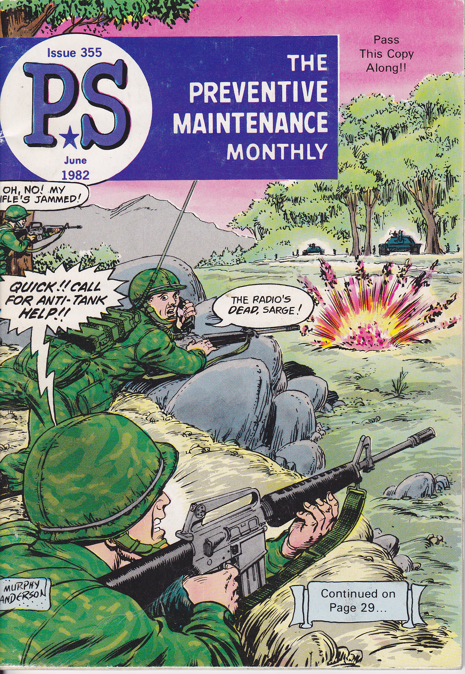
Preventative Maintenance Monthly
Fun Fact: Sounds from the handset on my PRC-25 were recorded and used in the sound track of a recent, major Hollywood movie. No BS GI!
Tks a heap for this info. I’m interested in what LRRPs used in Laos in late ’67, as I copied them and didn’t know what equipment they used. Did they encrypt voice msgs at that time (i.e. KY-38), or did they tape and send as ‘burst’ transmissions? Any info would be appreciated. thanks
Hi – From what I know, any of those methods would be available to the people who needed them. Probably any and all of those would have been used at some point. It would depend upon the ranges involved, whether A/C relay was available or direct ground-air comms were used. I know the GRC-109 (CW) was extensively used in those Shining Brass missions, probably with One Time Pads and direct CW to save the weight of GRA-71 burst components if the tactical situation allowed. Also a KY-38 is very heavy and very hard on batteries..in addition to its’ PRC-77 radio..
When you “copied” them, what were you using? That may help answer your question.
What about power from the batteries? I have heard that the battery is good for 40 to 80 hours.
I own a 25 and a 25B. Also, on the AN/GRA-39, The manual states that the batteries (6 in each unit) needs to be changed every 24 hours. My GRA-6 needs only 2 D-cells and a 45 volt battery ( I use 5 9-volt batteries in series). Works better and last for a hell lot longer.
And just a quick note, I beat the crap out of my 25s and they still work to this day.
Well I quoted the expected battery life from the Specification: 60 hours. But that depends a lot upon the Transmit-Receive ratio and also the operational temperature. We often had older batteries and they sometimes didn’t last as long as expected. It depended upon where they were in their shelf life and their storage temperature history.
Some Vietnam vets I have talked with stated that the PRC-25 was not very reliable, others stated otherwise. (I do a lot of operational displays at veterans events.) Unreliability has not been my personal experience with the 25 or 77 in the service. There are a lot of variables, but it really is a rugged field set.
Dear N6CC:
I HAVE READ YOUR ARTICLE ABOUT THE SET AN/PRC-25 LIKED ME AND PRETTY, HAVE A PROJECT TEAM TO RESTORE AN / PRC-77, I NEED TO GET THE BATTERY AND THE ANTENNA AND SET OF HEADPHONES, YOU WISH TO HAVE CONTACT PLEASE ADVISE ME QE. YOU SEND A GREETING OF FRIENDSHIP AND RADIOAFCIONADO.
Sincerely
JUAN MANUEL KG7GTI
Hola Juan – Response sent directly to you with possible sources for the parts you need.
73, Tim
I was a 31B20 Field Radio Mechanic in Vietnam assigned to HHC 1/5 CAV Oct 67 – Oct 68. More than once a RTO would bring in a PRC-25 needing a new battery pack because there would be one or more AK-47 round(s) lodged in the battery pack. I would replace the battery pack and cover and always clean and check out the operation. In more than one occasion the RTO wanted the old battery pack because it had saved his life.
Hi Bennie – Yes, some things never change, Radios and RTO’s can be a prime target. Indicative of their high value for sure…
Thank you for your service Soldier.
BZ
Tim
Being an old fart who actually did get the 12 month free vacation in the Exotic Republic of Vietnam back in 1970-71, I did get some experience with one of these sweet little radio’s strapped to my aching back, those damn crypto unit’s weighed in nearly at a ton, the way it felt when you got back from the patrol but they did do the job and those little yellow fellows who were trying to kill us were not able to listen in to our orders as we received them. Of course there were times when it didn’t make a damn bit of difference if they heard you or not, and at those times clear communications were more important then security, they could be bypassed for such things as calling in artillery or an air strike near you when the shit hit the fan. Sure wish I had one of those old set’s now though, I have my ham ticket, have had for years now, but my problem is funding, Can’t afford to even replace those cheap crap hand held’s from China that the FCC put the kibosh on a few years back by Bofeng. I do have an old Standard hand held that does a nice job but has a limited number of channels available. The China Crap I now have set up as a scanner but since the State has gone all encrypted, it isn’t worth a crap for that anymore either. At any rate 73’s DE KE0JBL
Bernie my MOS was also 31B20, from 69-70 with the 1st Infantry Division & then Air Calvary. Upon arrival in, ‘in country’, I didn’t touch any radios but was assigned to play the role of a grunt. Later, after they needed me to apply my MOS, I worked on radios. Also, since I had experience as a grunt, I played both roles; a grunt & a radio repairman. Thus, I also went in rat patrol in Thunder Road & didn’t touch a radio. Then, in Air calv., I was a swithboard operator. I guess a soldiers MOS is where they need him.
Hey Bennie. Served with HHC 1/5 Cav 68-69 February. General Motors 65.
On the Sensitivity issue are you referring to receive sensitivity?? If so the Tech specs on the bench is .5 uv at 80% modulation using a AN/USM 323 signal generator. Was a USMC 2531,2537,2841,2861 with my last 8 years at Electronics Maintenance Company Pendleton.
73 – 94.
Hi Gunny – Thanks for the input! That figure of 0.5 microvolts for receiver sensitivity makes sense. That would be typical of the technology in those days and not too bad even today. I think the original 1960’s manual did not specify receiver sensitivity directly since the test set in use then made that somewhat difficult. It was “pass / fail”. The later USM-323 (Hewlett Packard) made that direct measurement easier.
Your shop repaired some of the radios we were using down at Red Beach at the time. Got us back online in short order!
Thanks for your service Marine, S/F. Tim
Building 22220, ah, my best time in the Corps. Was in HF when I first got there, then Quality Control. The Prc-104s were just starting to come in when I left. Got there in 74, after Embassy duty, the left in 81, bound for 1st MarBrig in Hi. My favorite radio was the Trc-75, but they were all good radios and the troops did an outstanding job on all.
Always wanted to go Ham with a Prc-47, specially RTTY but could never get down to the Depot to buy one. Timing.
Now I’m retired twice over and got an “Angry-9” I’m putting together. Matching rcvr/xmter serial numbers but she’s got issues that need to be looked into.
Started out as a 2841, then 2847 till they dropped that MOS, became a 2861.
Tim, you have an OUTSTANDING website and it’s my main go-to place for info. I hope I can find a Military Collectors group here near Dallas, after I get my General ticket.
Semper Fi to all, and 73’s
Russell
Hi Russell – You have been around these old radios! The Angry 9 is a good place to start, very usable set…I prefer these older ones because I can repair them if necessary. The High Speed modern sets are pretty much out of reach for me technology-wise. Too specialized and complex! Thanks for stopping by my website and have fun with your GRC-9…
S/F and thanks for your service,,Tim
Any idea how to connect an ls 454 loudspeaker to a prc 25? My h161 headset works but I can’t get the loudspeaker to work
Hi RL…The LS-454 speaker connector will need to be rewired.. The wire on Pin E needs to be moved to Pin B to work with these portable sets. See link for further:
http://www.prc68.com/I/LS454.shtml
Tim
Tim,
Australian SAS patrols apparently sent Morse on some of their PRC-25 sets. “Patrols operating close to Nui Dat also used the VHF AN/PRC-25 Radio Set however it took up a lot of pack space and rations plus water had to be split up amongst the other patrol members. An adaptor was sometimes fitted to the AN/PRC-25 radios, which enable the patrol signaller to transmit to base in morse code while the base station could reply in voice.” That mention is at page 2 here-
http://pronto.au104.org/Pronto_Book/ProntoSVN_CH5-2_2012.pdf
Do you have any more info on this?
Bill W8FIX
Hi Bill – Thanks for that info and link. An interesting read. But I wonder what was going on here. Adapting the PRC-25 for CW would not lighten their load as implied, nor would it extend the range of the radios, presumably via MCW into the FM transmitter. I wonder if there is a typo here; maybe a different radio?
Thanks – good eye! Tim
Found info on the Australian MCW adapter. It was made around 1972 specifically for the PRC-25 and PRC-77. The purposes were “to increase the operational range of the radio set and to provide a quieter means of transmission than voice when operating in close proximity to the enemy.” It also worked with the GRA-71. The adapter is small (54 x 52.4 x 31.8 mm; 163 grams) and fit on the 14 pin dummy plug on the radio’s front panel. Battery drain was negligible. Closing the key generated a 2 KHz MCW tone and also keyed the radio and kept it in transmit until 2 seconds after keying stopped. Nomenclature is Adapter Set, Morse Transmission, MX-F2. Don’t know how many were made and whether any survive.
Hi Bill – Good find! I’ve never heard of that idea or hardware. Very curious about how MCW with an FM set would increase range but it certainly has the potential to keep transmission quieter while in use. Clever idea. And with a GRA-71! I’ll dig around and see what I can find as well.
I can see that the ability of sending burst CW via the GRA-71 on a VHF link could come in handy – with or without an intermediate relay…Would provide some transmission intercept security without the weight and bulk of a KY-38 for example..
Thanks! Tim
Found more background on the MCW adapter. Turns out that using an external device to send MCW on tactical FM sets was around in WW2. TM 11-351 for the TG-5 field telegraph set says the TG-5 “will operate satisfactorily as a tone keyer with any Signal Corps radio using a standard carbon button microphone such as radio sets SCR-300, SCR-508, SCR-510, SCR-608, SCR-610, and SCR-619.” All it took was making up a cable with PL-55 and PL-68 plugs and a 400 ohm resistor to prevent RF feedback. Also have seen a note that using MCW sometimes helped overcome jamming. Improvise, adapt, overcome.
Any chance you could provide more info on how you’re powering your ’25? I’m currently using external 12v power. I don’t know which pins to use fornthr 3v to the amp.
Hi Steve – I am using a rechargeable 12 volt SLA battery for A+, plus two D Cells in series for the 3 volt tube filament via a 1 ohm DIY current limiting resistor. See text above. Works great, they all fit inside the stock battery box… The best way to describe the wiring is to look at the BA-4386 battery connector diagram to get the pins right. A picture being worth a thousand words….Take a look at Brooke Clark’s great website for details…http://www.prc68.com/I/2577Battery.shtml
Thanks for visiting my website..
73, Tim
Sir,
How In the world do I repaint the little letters and numbers
On the top of the prc-25
I’d like to repaint the entire radio too
Mike
Hi Mike – good question. Since the labels are raised above the panel it becomes easier. After you repaint the entire panel you can reapply white paint to the letters by using a pencil eraser dipped in white paint. Get a new pencil, slice the eraser cleanly with a razor blade to make a flat surface. Apply just a little paint to the eraser and then transfer it to the tops of the raised letters. Takes some patience but it works..
Good luck! Tim
What’s the best method of disposal of the magnesuim battery pack? Can they be land-filled or even better recycled?
Thanks in advance,
Sean.
Hi Sean – I don’t know offhand. Our local waste management company accepts magnesium-chemistry batteries for recycling. Best to check with your local waste management company or your municipality for specifics.
Tim
Thank you for the excellent article. Have started getting back into green radios for operating on the bands and living history displays. Just recently acquired a PRC-25.
73,
Tom W1WSO
Have fun with it Tom – and thanks for visiting….Tim
I carried the AN/PRC-77 and hated having the KY-38 underneath it. We used to call the KY-38 “The Green Machine”. The interconnect cable always went bad where it went into the KY-38. The book spec for the BA-4386 was 24 hours with a 9:1 transmit to receive ratio. To disable the harsh 150 squelch tone, short power pin J to ground.
Hi Ron – Yep, lots of Gravity in that system! That cable is certainly a mechanical weak spot. We had no problems drawing a KY-38 and the KeyMat but the dang interconnect cables were hard to come by. I think “integrated COMSEC” was the way to go, but nothing is “simple”…
Thanks for your service!
Thoroughly enjoyed reading your page, last time I saw a jungle antenna was 1969. Was in 5th SFG in II Corps, Montagnards were outstanding tree climbers, they could get the antenna up amazingly fast. One other note: the PRC-25 battery was the source of another very important piece of equipment- the heavy-mil plastic wrapper was the best map case ever, sealed with LRRP ration tape your topo was bone dry.
Hi Mike – Thanks for adding some “ground truth”…Yep… Those battery wrappers were also excellent to keep the handset dry -ish. Simple, important things..
Thanks for your service and for stopping by…
Cheers, Tim
The story of the PRC-77 does not end in Vietnam and should be told further, especially when we think of the further technical developments of the device by the German company Telemit in Munich or the changes made by the Austrian army. And not to forget the role that the PRC-77 played in the CIA’s Operation RUBICON, together with the West German secret service in the late 80s
Hi Harald – It’s true, the PRC-77 was used by the US and others well after 1975, my unit used them in-theatre during the Gulf War in 1991, they still did the job well. However in US service they were being phased out by the SINGCARS radios but many units still retained them, including Reserve units and probably in some training unit activities maybe even today. Many good modifications to the design were done by allied countries, not the least of which was the inclusion of a 25 kc channel spacing to double the number of discrete channels available. I guess that such later modifications (including outboard crypto and audio/PS/Amp accessories) done outside the US would no longer technically be considered part of “AN/PRC-77” radio systems. The design is readily adaptable to things like replacing its discrete circuitry with more modern LSI/ASIC circuits to improve performance and reduce power consumption.
Thanks for your input and for visiting my website – Cheers! Tim
Hi Tim, I just acquired 2 PRC-25 radios with couple compatible antennas from a SK estate .
1 of the 25s supposed to be working 5 to 8 years ago, other was held onto to as a spare parts radio. I’d like to power them up from a bench supply setup but can’t find a a schematic for a homebrew bench supply setup that will deal with the filament inrush current issue. I didn’t see anything as such on your website but maybe I missed it. I managed to keep the PRC-25 off my back in Nam 68-69 serving with 101st Airborne as I got into MARS station at my LZ – Lucky me ! Buit now I’m itching to light up this radio and see what I missed – It appears radio runs on 12 to 15V and 3 V for filament but needs some sort of inrush current protector. I got plenty variable and fixed bench supplies around – will setting the current limit on the 3V source supply protect the radio filaments / 73 Dennis N6KI
Hi Dennis If you operate them from an adjustable PS, just set the filament voltage to 2.5 VDC, then no series resistor necessary. Put 12-15 VDC on the Vcc line and you should be good to go. PM Sent….
Thank you for your service Soldier!
Tim
What an incredible website! I am amazed by the detailed information and accurate descriptions provided about the PRC-25 radio. The layout is user-friendly and easy to navigate, making it a go-to resource for anyone seeking knowledge about this iconic device. The owner’s passion and expertise truly shine through, making this site a true gem for all radio enthusiasts. Thank you for creating such a valuable resource, it’s greatly appreciated! Keep up the fantastic work!
Best regards
Hello Tim! Great page and article. Used these radios on my tank and on my back as a scout in the Army. I acquired a USMC rebuild 25 model from Barstow some years back. In fact, mine is serial number 253! Anyhow, the function switch broke off. Any idea who can replace it for me? Also, can you sell me a battery adaptor? I have a few cases of Mag batteries but I’m sure at this point they are all dead. Any help with this would be appreciated! Thanks and cheers!
Hi Tom – OK on your PRC-25. Yours and mine may have been neighbors while at USMC Barstow..
I don’t have or sell any battery adapters but you can easily put some cells together to power yours. I use two 6 volt SLA batteries in series for the 12 volt circuits and a separate D Cell for the filament voltage as described in my post article. Probably other solutions for the PRC-25 out there on the Interwebs too… I assume you mean the function switch KNOB broke off? If so try contacting Fair Radio Sales in Ohio – they likely will have a replacement knob. If the switch itself is missing or damaged, a much bigger problem of course, maybe Fair Radio has a replacement available.
Thanks for visiting and thank you for your service, Tim