
UPDATED 2/9/17
Both the GRC-9 and GRC-109 used the BA-48 battery to power their respective receivers as an option. When operated from the various dynamotor, vibrator or AC supplies, the receivers were also powered continuously. However, when operating in the field from the G-43 or GN-58 hand-cranked generators, a receiver battery became very handy.
Starting with the receiver power supply:
When keeping a well-disciplined Net schedule, the hand cranked generator powering both the receiver and transmitter might have been remotely practical, but in guarding an Alert Net or other continuous receive requirement in the field, the BA-48 battery was essential.

BA-48 Battery
Above: The BA-48 battery. Note the date code of May 1984

BA-48 Powered the GRC-109 Receiver
Since a fresh BA-48 is currently unobtanium and since I do a lot of operating of these radios in the field (often by myself) a continuous power supply for the receivers was needed. So I designed a compact DC-DC converter that provides 100 VDC and 1.4 VDC (regulated) from an external 12 volt battery. This could either be a vehicle battery or more commonly, a 12 volt Gel Cell. I chose to regulate the 1.4 VDC filament supply to protect the tubes from Murphy’s Law, making it “soldier proof”.

GRC-109 Receiver powered by DC-DC Converter – N6CC
The first GRC-9 prototype supply (gold box) provided power to a 4-contact female cable plug (gray cable, seen above) that mated with the receiver battery connector of the GRC-9 Transmitter-Receiver. It works great and is very quiet, running at approximately 20 KHz, no mechanical, acoustic or electrical noise is evident.
It uses a custom – designed ferrite core transformer with separate secondaries for each voltage and it draws about 500 ma during receive. (The GRC-9 prototype power supply was designed to be powered primarily by a 12 Volt vehicle battery so design simplifications were made at the expense of efficiency.) I later decided to add a capability to allow it to power the GRC-109 receiver as well, but as usual, a custom connector was needed. The 4-pin battery connector in the GRC-9 and GRC-109 receive systems are unique to those radio as far as I can tell. What to do?
So I built up a prototype connector and attached it to the power supply so the ‘109 receiver could plug into it directly, just like the BA-48. I made the female connector from a 1/2 inch white PVC pipe end-cap for a housing and used 4 “molex” – type female sockets from Radio Shack connectors (R/S Part Number 274-154. Note: The R/S catalog mis-identifies these sockets as 0.093 inches – they are actually 0.125 inches!). These are made for 0.125 inch OD pins, the exact size as the ‘109 receiver power pins.
I positioned the females inside the pipe cap using the receiver male plug as an exact alignment positioner. I then filled the connector with “hot glue” from a glue gun, squirting the molten glue inside via two access holes in the pipe cap. The solidified glue holds the 4 sockets firmly in place and the pipe cap is attached to the PS cover with a #8 machine screw. The leads penetrate the cap and cover through a small access hole. The connector is very rugged, water tight and should be good for several kilovolts insulation-wise.

GRC-109 Receiver DC-DC Converter
Above: The completed connector is very rugged and should be even stronger than the rubber-insulated female connectors provided for in the stock system.
The power supply should run the receiver for several days of casual ops in the field on a 7 Amp-Hour Gel Cell. That battery can easily be recharged by a small “dashboard-type” solar panel sold to keep vehicle batteries topped off while I’m doing other stuff at camp. We’re talking indefinite ops here. Next project: maybe build this system into a BA-48 replica. Then, a similar design as the Nems Clarke 12 Volt “Power Adapter PA-109” for the entire GRC-109 system so I don’t have to crank and send CW at the same time.

GRC-109 Receiver with battery power
The power supply powers the receiver while the PU-181 powers the transmitter. In a quiet location like this, inverter “hash” would be obvious. Nothing heard!
Transmitter HV B+ power supply design (10-28-12) Work-in-progress…..
Just starting on a power supply design to provide about 425 – 450 VDC at 100 ma to power both the GRC-109, RS-1 and RS-6 transmitters. For now, I’m concentrating on only the B+ requirements, the TX filament supply to follow. This supply will be run from a 12 Volt lead acid “garden tractor” battery with much more “camping” lifetime in the field than the Gel Cell currently powering just the receiver.
When complete, the intent is to integrate both the TX and the previously-built RX supply design into a common circuit using this single ferrite core transformer. The following work done on my PS test bed fixture with HV dummy load resistors.

Prototype GRC9/109 TX B+ Power Supply
Initial bread board prototype on my PS Test Bed.

GRC-9/109 TX DC Power Supply Development
Above: So far so good on initial power-up. Delivers about 415 VDC from a 13.6 VDC input. Efficiency = 68%. Not real great efficiency, but getting there as I learn the Black Art of high frequency ferrite transformer design. Needs a few more secondary turns too. Output Ripple less than 0.25%. The scope shows the Base drive and Collector waveforms. Pretty clean. The 3 big black resistors mounted on the aluminum plate are the HV dummy load resistors simulating the transmitters’ B+ load.
Lots more to do, but I think I will package the integrated TX and RX supply into a spare GRC-109 transmitter case that will power the GRC-109 and RS-1 sets in the field. It could also power the RS-6 sets as soon as I can figure out those connector issues. A switched tap to provide 580 VDC for the GRC-9 transmitter would also be simple, I designed-in plenty of primary drive power capacity to handle it. Or maybe a separate GRC-9 TX power supply inside. Stay tuned.

GRC-109 DC-DC Power Supply Beginnings N6CC
Above: Anyone remember Heathkits? “Learn by doing”. This is a “build from scratch” using mostly Junk-Box parts on hand…..

GRC-109 DC Power Supply Parts Layout
Above: Shake the junk-box and see what falls out. Scrap aluminum panel, figure out where all the parts will fit the best, drill a bunch of holes. All the transmitter power supply parts mount to the front panel, the receiver P/S mounts to the case.

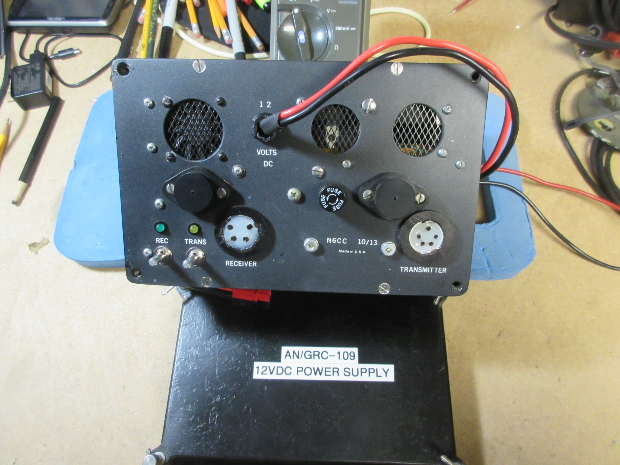
GRC-109 12 VDC Power Supply – N6CC
The panel came out reasonably well; the parts didn’t take up too much volume in the surplus GRC-109 transmitter case. I applied some sexy Black Satin paint and added a “Made in USA” label. (Well there goes my plausible deniability!) I have to get some plastic caps for those TO-3 transistors, the cases are the Collectors and carry the primary square wave.
Those holes in the corners are for the threaded thumb screws used to attach the stock-issue environmental cover plates, just like the rest of the system components. The DC power wires with Power Pole 30 amp connectors roll up inside the cover. Ready for burial in the swamp.

GRC-109 12 VDC Power Supply – N6CC
Above: Design and fabrication complete, testing underway, it’s On the Air, it works great! I included a small fan for forced-air cooling which I might need if I include a GRC-9 transmitter power supply inside in the future. (If I can find a female chassis connector for one!). Just powering the GRC-109 the supply runs barely warm to the touch.
The only significant heat source is the wire wound dropping resistor for the 6.3 volt DC (despite the 6.3 VAC error on the below schematic) transmitter filaments. I couldn’t quickly come up with a simpler, more efficient method for powering them without the heat loss.
The receiver power supply is electrically very quiet. The transmitter supply is also quiet in the receiver above 5 MC or so, but some switching harmonics can be weakly heard in the receiver down on 80 meters with the TX supply running. Need to review the component grounding scheme. Otherwise, so far, so good.
Load and Line regulation is good, with 12.6 VDC input although it is a linear circuit except for the receiver filament source. It draws about 800 ma with just the receiver section turned on, about 4.8 amps with both sections turned on and the transmitter “key down”.
The GRC-109 connectors are made from PVC 3/4 inch threaded pipe adapters with stock Molex female pins held in place with hot glue. Bullet proof, simple, not real pretty. The former stand-alone receiver power module is now installed inside to power both the GRC-9 and GRC-109 receivers.
Now, some systems test and then off to The Bush for a shakedown cruise.

12 Volt DC-DC Converter powering the GRC-109 Receiver
Above: The converter can power both the transmitter and receiver with a small Gel Cell like this but it’s best to power the transmitter directly off the G-43 hand cranked generator and use the Gel Cell for the receiver only. The Gel Cell will run both just fine, but not for a lot of transmission time of course. Better use the garden tractor battery and leave the G-43 at home. That would power everything for a week.
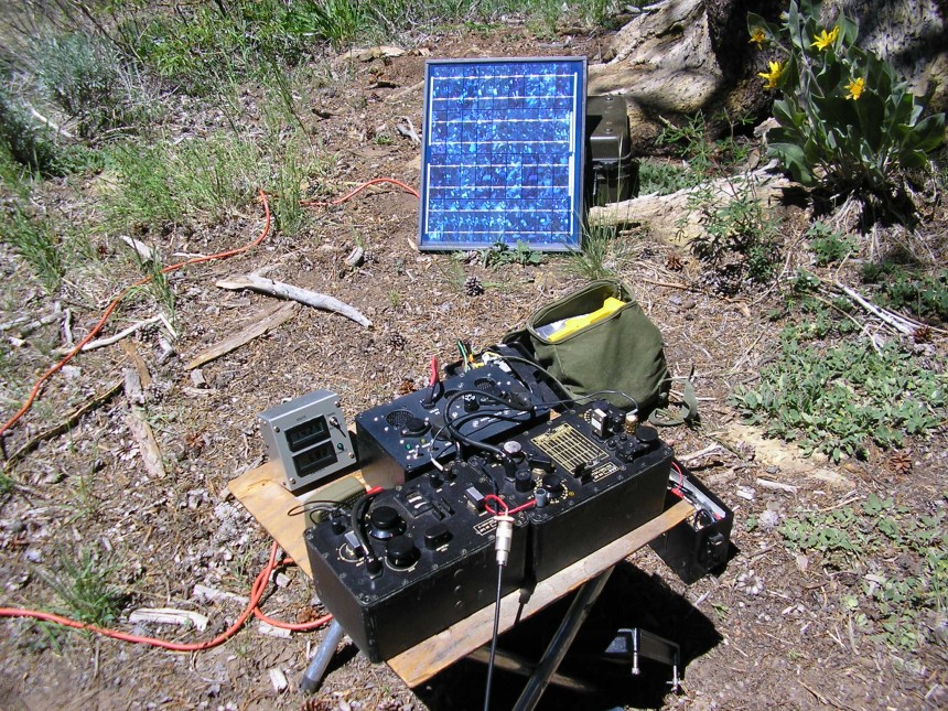
Solar Powered GRC-109 in the Field
I’ll include the schematics once I am satisfied I don’t need to tweak the design. However, the high voltage supplies are built around ferrite cores that I happened to have in the Junk Box, pedigree unknown, so it may be difficult to replicate. The magnetics are the heart of the design, otherwise just standard HVPS design with regulated +1.4 VDC for the receiver filaments. As a consequence, this post is more about “what can be done” versus a detailed “how to do it”.
UPDATE: So here’s the current prototype schematic which may have morphed a bit along the way. It could be used as a starting point for anyone who may want a similar piece of equipment. I need to get some CADD drawing software,

GRC-109 12V DC PS Prototype www.N6CC.COM
As with any “One Of” designs, many compromises were made to utilize parts and space available. Component ratings, wire gauge, transformer design, safety factors etc were driven by space and junk-box part realities. Since my application included the availability of a large 12 volt battery for primary power, I was able to keep it simple at the expense of some efficiency.
To improve efficiency I could have used base drive windings for the receiver HV oscillator transistors rather than the simple resistor drive shown. I could have also designed a more efficient 6.3 VDC source for the transmitter filaments rather than the big wire-wound DC dropping resistors shown. Magnetics also determined the oscillation frequency which is 8-9 kc, basically outside my (current!) hearing range. Reducing that frequency would have resulted in somewhat improved efficiency but that would have required better filtering. A tradeoff.
The supply runs fairly cool so that little re-purposed CPU fan is really unnecessary but I included it for a future upgrade to include a transmitter B+ supply for the GRC-9 set. Then additional cooling might be needed. We’ll see.
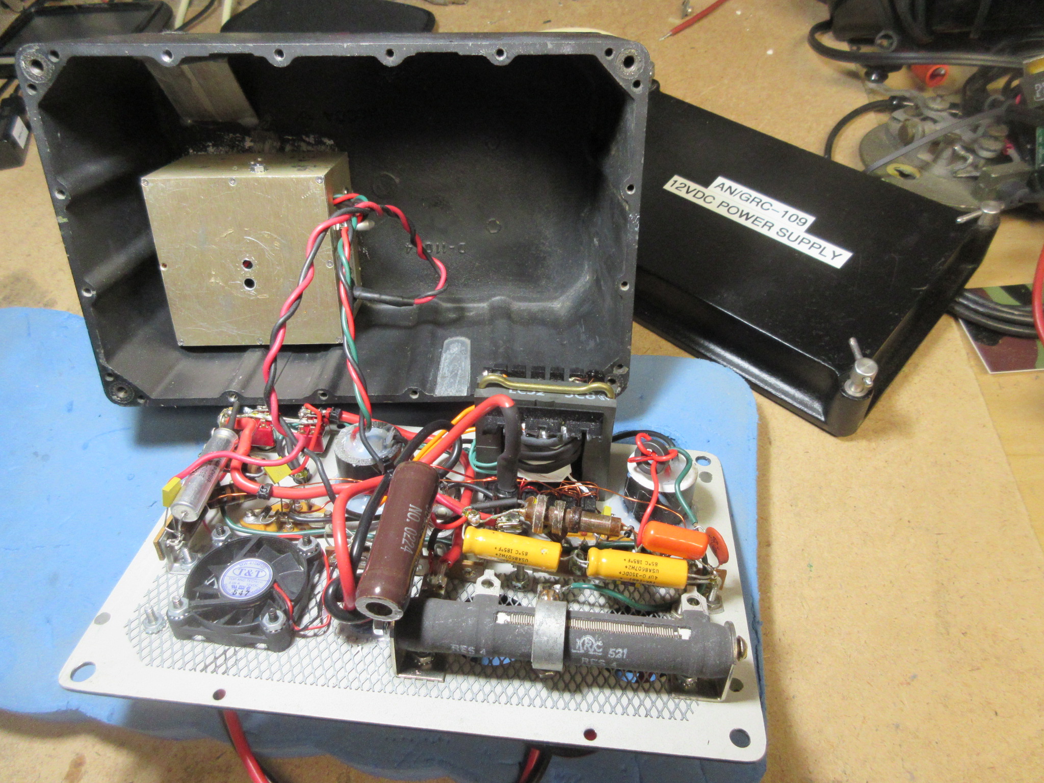
GRC-109 12 volt DC power supply N6CC
The receiver supply which was previously built is now mounted inside the box along with the other circuitry. It is inside the shielded box mounted to the case.
Finally got some TO-3 insulating caps for the panel transistors.
GRC-109 12 VDC Power Supply packaging N6CC
Then on to another successful field deployments: ARRL Field Day 2018

AN/GRC-109 station outside the camp barracks.
I love the sound of CW in the mountains…..
Thanks for posting this. My battery died quite a while ago and I’ve been putting off making a power supply until now.
73
KI5KT
The Ba-48 is a bunch of AA cells and D cells.
Carefully remove the outer cardboard.
There is black tar inside that will stick to cardboard as well as anything else.
Do this outside on a hot summer day.
The Solid State power supply for a AN/PRC-6 works
Hi, Have you done any more work on the 12vdc power supply for the 109? I am interested in building one but lack the knowledge .
thanks
Jon – KM6OP
Hi Jon – well I have not made any further improvements to the supply as yet. I am still looking for a connector for the GRC-9 cable so I can power both types of sets but so far, no luck. They seem to be rare, only appearing on the DY-88 and 105 dyno supplies which no one wants to part-out..
I need to get my notes out and at least draw up a block diagram of my design as a starting point. There were several compromises made to accommodate specific junk-box parts I had available (like the HV transformer core/bobbins, filament drop resistor etc). I’m not sure it would be easy to replicate, especially without that exact ferrite transformer core (no longer available), but a block diagram might get you started. Unfortunately I didn’t have the resources to design it with commonly available parts so it could be replicated. My bad…
Anyway, give me some time to get a sketch made – it will be pencil and paper, no CADD capability here….
For an “easy fix” you could just get a 12 volt sinewave type inverter that runs off 12 VDC. Then just plug your AC supply into that, you are in business…no building necessary.
73,,Tim
Hi Jon – I finally got around to transcribing the PS schematic from my notes. See above updates:
I wouldn’t recommend trying to duplicate it exactly as shown due primarily to the obsolete magnetics I used but it could be a starting point for you. FYI Tim
Tim, I follow your endeavors occasionally and also own a complete GRC109 set. I have the rcvr of the GRC9 as well for which I want to build a ps. I saw you made your own connectors for GRC9/GRC109. I have been looking for some of the cables to power the units up using my own home brew ps.
That being said, check ebay (Fair Radio Sales) item numbers 192430093470 and 192430093490. I think you may find them of interest.
Also is there an annual event (day) dedeicated exclusely to mil commo equip both on the air and hamfest/gathering as it were?
Thanks, Mike
Hi Mike – Thanks for the note. Yes, those are very handy cables for powering the GRC-9 receiver. probably fair prices as well. The matching (female) connectors on my DIY power supply have worked out well – Molex contacts, hot glue and a PVC fitting for a housing.
As to operating events, there are some “Military” nets on, they are listed in the Electric Radio magazine but also via the various Yahoo Groups sites. MRCA, ARMYRADIOS etc. Some are AM, others are SSB, the east coast guys also run a CW new I think. All are pretty informal and always subject to propagation…Those groups also hold annual swap meets/rallies around the country.
Thanks for visiting and have fun with your field sets!
Tim.
Tim,
I am purchasing a GRC-109 TX, RX, generator with legs/seat/cable and pp2684. I’ve been reading the info on your site and especially your GRC-109 12 VDC Power Supply project. I am a good op but I am “the world’s best cold solderer,” so building anything is not my expertise. Do you have an eBay site for purchasing your GRC-109 12 VDC supply? Is there a BA-48 battery adapter out there for using common D, C, AA, etc., batteries as a substitute? I’m I correct the RX portion can operate off a 6V battery but not the TX portion?
Thanks for taking the time to answer this.
73, Dave KB2KBY
Hi Dave – Another GRC-109 on the air soon! Good deal..
The power supplies I show on my website are “one of a kind” and built for my immediate use, I have not built additional ones, or offer anything for sale. It was mostly for my engineering hobby as applied to the 109 here. The little (gold) supply runs only the receiver, the larger black supply includes the receiver supply plus a high voltage supply for the transmitter as the schematic shows. 12 volt input.
You might take a look at K4CHE’s excellent website. He shows how to make a BA-48 simulator using D Cells and 9 volt batteries to power the 109 receiver. Take a look here:
http://k4che.com/BA48/BA48pg1.htm
You might also do a web search, there may be others who have made 90 volt/1.5 volt power supplies – that is a common type needed for the old battery operated receivers.
Another route is to power your new AC supply with a 120 volt sinewave inverter from a 12 volt DC source. An off the shelf solution. Make sure it is a sinewave type, not a cheap square wave or “modified sine” type – those generate lots of RF noise….
Have fun with your 109 – Mine gets lots of use!
Tim, you were kind to reply to my last GRC-109 question in which you recommended the use of a pure sine wave convertor powering the 109. (Any reason why not just a 6v battery to the power supply?) Any minimum and/or maximum wattage recommended for the pure sine wave? Recommended 12v battery with the amps for use with the pure sine wave convertor? You said in one of your problems for the R-1004 to look at the tubes and use a special grease as they oxidize. Where can you purchase that dielectric grease? I can see easily all the top screws to take out but what about the one big brass screw and three brass screws on the sides? Just simply take those side screws out first? No big trick to them? (I am a very elementary novice on the 109. Any manual that can be downloaded to show the breakdown? I’m a visual person plus reading type guy.) I’m chicken to power things up at the moment. I actually got a very low serial numbered set!, both just double digits. TNX for taking the time to answer these questions. Take your time for the reply. 73, Dave
Hi Dave – Good questions! Power supplies: The large PP-2684 PS was designed to run off AC or a 6 volt DC “car” battery. That’s how it was designed and should work but the vibrator in the PS that converts 6 VDC into 6VAC will probably not work right off.. The internal contacts oxidize over time rendering them Inop but they can be disassembled and cleaned. (Lots of info on the Interwebs on reviving vibrators..) I found with mine that the vibrator PS generates a lot of “vibrator hash” noise in the receiver and 6 volt car batteries are hard to find so I decided to not go that route for my actual field ops.
A pure Sine wave inverter generating 120 VAC is an easy solution to power the setup. Mine is a small 300 watt job (Samlex) and it works well off a small 12VDC “garden tractor” battery although any similar 12V car battery will work fine, at least for testing.
Grease? I use silicon “ignition” dielectric grease from the car parts store on the rubber case-chassis gaskets, not on the tubes. The tube pins (and bandswitch contacts) may be oxidized from age so alcohol or Deoxit contact cleaner works well if needed.
Disassembly: The big brass “screw” in the case corner is a container with dessicant material to keep the internal parts dry, it is not structural but must be removed to get the chassis out of the case. The 3 small brass screws on the side of the case allow access to alignment adjustments and don’t need to be removed to get the radio out of the case. The Army manual is here – should tell you pretty much everything you need to be aware of for disassembly/operation: http://radionerds.com/index.php/AN%7EGRC-109