UPDATED 6/7/2023
“Executive Summary”
- Antennas can have high gain, high bandwidth or small size. Pick any TWO.
- Every antenna is a compromise
- Put up a resonant dipole
- Have a nice day (outside!)
The Question: What do you want your portable field antenna to DO?
The employment of these antennas is generally for my portable field Ops, typically camping or otherwise vacation/road trips. My focus is on regional comms with my family, my buddies and EMCOMM groups on the Low HF bands and local comms on VHF. I’m not into chasing long distance “DX” very much but any of these horizontal wire antennas will work over very long ranges especially when elevated to around a half wavelength.
A simple kit for temporary, lightweight, deployable wire antennas is essential for any field Ops. No “Rocket Surgery” here, just proven, simple, efficient systems that work very well in a field environment. Included is my experience-driven rationale for what is in this kit and what is not, and why.
Described below is my kit as it fits in a standard US Military M-1956 “Butt Pack”. I have used the types of parts and techniques in this kit for 50+ years and it supports almost any kind of field (or home) radio installation from HF through 6 and 2 meters.
The simple, effective half wave dipole. Write this equation inside your helmet: L = 468/f Where L = end-to-end length of the dipole in FEET, f = operating freq in MEGACYCLES. Eg: on 3550 kc, L = 468/3.55 = 131.8 feet long.
Here is a cool 1950’s tape measure for field antenna work. Measure from the dipole center, pull it out stopping at the frequency you are using. It then shows where to cut the quarter wavelength wire for that freq. Lowest frequency (maximum length) indicated is 17 mc. (VHF and upper HF.) With an alligator clip to your transmitter it can become a portable quarter wave monopole.

Antenna Tape Measure

Antenna Measurement Tape
Sun’s up? Freqs up. Sun’s down? Freqs down.
For local and regional HF, I usually use a double dipole with legs for both 40 and 80 meters (and sometimes including 60 meters), fed in parallel from the same feedline. This covers both day and night time freqs without having to change anything while camping.
Known as a “fan dipole” the double-dipoles have been in the Handbooks since the 1930’s; it’s the electrical basis for the military AS-2259. When deployed “low” for NVIS applications dipoles are also known as “cloud warmers”.
The kit also includes extra wire for dipoles, half-rhombics and Vee beams on other bands. It includes pre-made Jungle Antenna ground planes cut for 28 MC and 51.0 MC plus a twin-lead J-Pole vertical for 2 meters. Just simple, effective and proven antennas. Locally customize as required, you won’t need to bring ALL this stuff if you’ve done a little pre-planning.
“It’s a brave person who can admit to using a store-bought antenna”
Some guy.
Unless you are set up on a 5 square foot balcony under observation, in the Sahara or on the Ross Ice Shelf (no vegetation to support at least one end of a wire), forget those “Buddipoles”, “Isotrons”, “Loops”, “Hamsticks” and other such marketing miracles.
If you have the space, and can “pull it off”, put out a quarter wave HF wire to the nearest support, even if it’s just laying on top of some 3 foot scrub. Place another quarter wave wire in the opposite direction on the ground or laying atop more scrub. Maybe some kind of LC coupler if your radio needs it. You’ve made a Hasty Dipole. See below.
Although it won’t outperform a somewhat elevated dipole, this will clearly out perform any expensive, short, loaded, lossy “leaky tuned circuit” or transmit loop contraptions. Particularly during “receive” due to the tiny capture area of all those severely compromised antenna designs. Plus, you can roll it up and transport it in your pocket.
Loops are excellent for direction finding and can be very effective at nulling out specific local noise sources otherwise getting into a receiver. Not so much for a transmitter antenna. Their radiation efficiency is very poor even though their SWR can be tuned/transformed to 50Ω, just like a dummy load. Beware.
But I get it – absolutely no room for a good antenna? Loops etc are better than nothing.
These wire arrangements will also get your antenna away from all those noise sources inside and around the typical inhabited structure. VERY important. But this post is about a portable, field antenna kit.
Wire HF antennas are simple, lightweight, cheap, compact, easy to deploy and EFFICIENT! It’s basic physics. If its long RANGE (> 2000 km) that you are after, mount the horizontal wire antennas 1/2 wavelength high.
An antenna engineers’ Axiom as above:
“You can have High Gain, High Bandwidth or Small Size. Pick any TWO”.
But my Buddipole has a 1:1 SWR !
So does a dummy load…..Think about that…
Sorry – Flame Shields Up….
My portable field antenna kit:
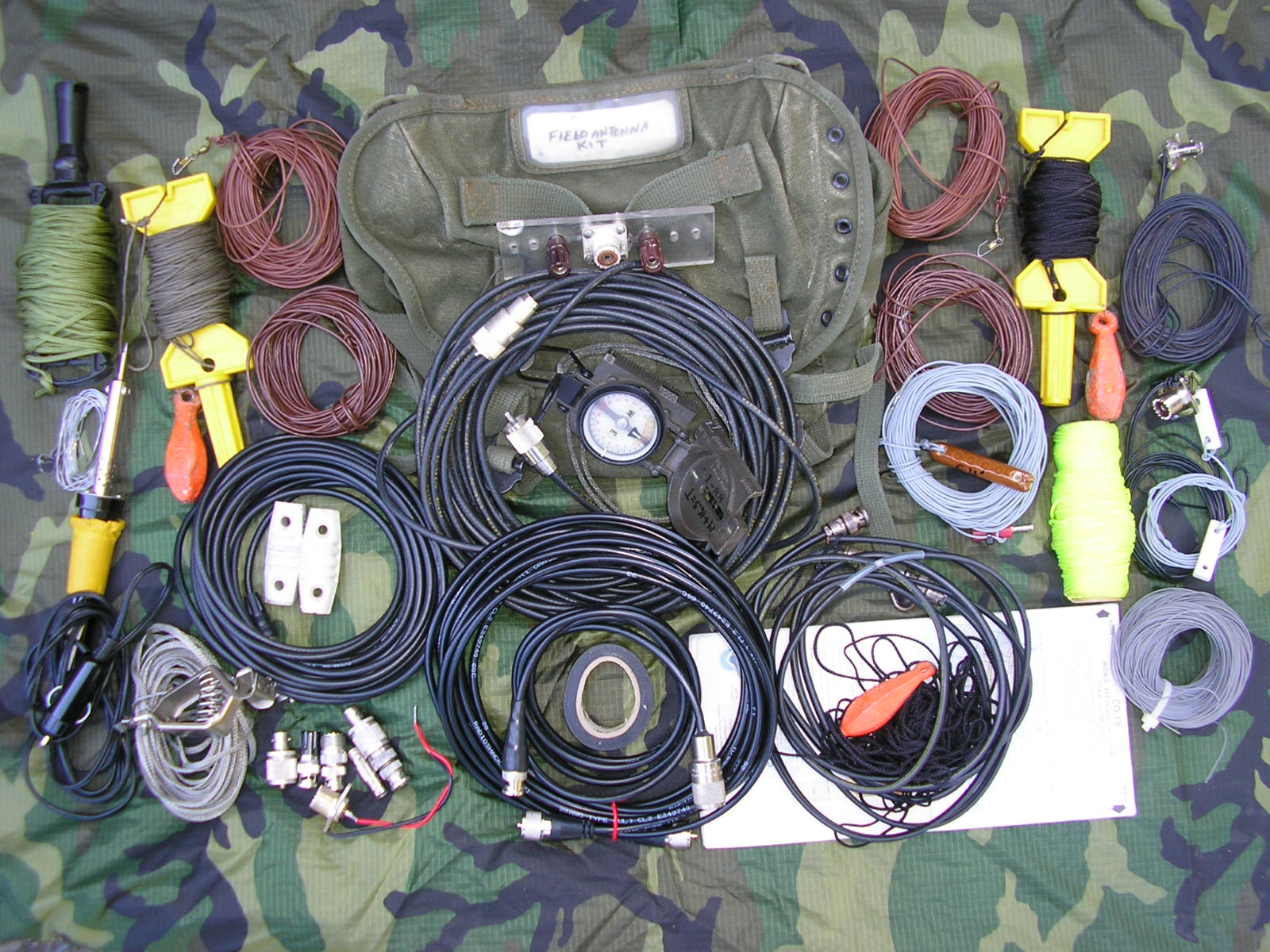
Field Antenna Kit – N6CC
As shown, the kit contains the following:
Lightweight HF dipole center insulator with terminals and SO-239 Coaxial connector.
Dipole 20 AWG insulated wire legs for both 80 and 40 meter dipoles. Note fishing snap swivels for far-end attachment to halyards.
One 40 foot RG-58C/U coax feedline with PL-259 connectors
Two 20 foot RG-58C/U transmission lines, one with BNC and the other with PL-259 connectors.
3 each nylon heaving lines / halyards.
Three 8 Oz fishing weights for launching into trees.
One “high visibility” heaving line / halyard.
One 1/4 wavelength insulated wire with insulator and banana plug for HF or ground wire array needs.
One coil 200 feet 26 AWG insulated wire for halfwave ground reflector wires or stealthy/halfwave antennas on other freq’s.
One 2 – meter twin lead J-Pole and coax feed line with heaving line and fishing weight.
One 6 – meter “Jungle Antenna” ground plane cut for 51.0 MHz, photo below, details seen elsewhere on this website.
One 10 – meter “Jungle Antenna” ground plane made with WD-1/T commo “slash” wire.
One 12 volt soldering iron with cigarette lighter plug, solder and electrical tape.
One lensatic compass with aviation Sectional map of my usual Op areas. (aiming antennas)
Two porcelain end insulators.
Assortment of BNC – UHF and wire adapter connectors. One BNC-UHF jumper cable.
One 20 foot (adjustable) length of ground braid (keep it short!) with alligator clip.
M-1956 Canvas Butt Pack to contain the entire kit.
I see that there is now a company marketing a very stripped-down version of this kit for partial functionality. The $300 price tag includes conventional wire-wound ( ! ) end termination resistors. (The inherent inductance of typical wire-wound resistors completely defeats their purpose as terminations for unidirectional wire antennas.) So if you build your own kit you will probably better understand its design and usage.
“There IS a way. The easy way is always mined” Murphy’s Laws of Combat
“There is no free lunch” The First Law of Thermodynamics
Why Coax? With the resonant HF antennas that I use, the RF transmission line losses are low and acceptable. (There is nothing magic about antenna “resonance” as far as effective radiation goes. The resonant antenna just helps keep the feedline losses to a minimum). Coax is flexible, tolerates rain, rolls up into a compact kit, “connectorizes” fairly easily, deploys and retrieves easily and is pretty hard to see.
These are all advantages over twin lead, ladder line etc. although open wire lines like those are very “low loss”. For a temporary, resonant HF dipole in the boonies, not too high up and that fits in this small kit, coax was the transmission line of choice. I use RG-58C/U.
Although I carry a couple, I usually don’t use “formal” insulators at the dipole ends. I don’t run more than 100 watts (PRC-47), usually just 10-20 watts or so from the smaller field sets. The nylon halyards provide more than adequate insulation, even when wet. I use brass fishing snap swivels at the dipole ends to provide a quick connection to the halyard and these also eliminate twisting and kinking of the wire and nylon halyard while winding back up. They also “pull” more easily over a branch than a big insulator would – big insulators can get hung up on small branches. White or glass insulators can also be quite visible.

6 Meter “Jungle” ground plane antenna with bamboo spreaders
Above: the Jungle Antenna deployed for 51 MC operation before being hoisted up to operational height. Simple, effective, long-range, lightweight and fits in your BDU pocket. Just find some local sticks for spreaders; bamboo as used here is perfect.
(See Field Expedient Antennas post for further details and variants.)

Jungle Antenna – BNC Connector
Above: A Jungle Antenna made with the older style WD-1/TT commo wire utilizing a standard BNC chassis-mount connector. The 4 radials (in this case) are soldered to the 4 mounting holes in the connector flange, the vertical radiator wire is soldered into the BNC center pin. This one is pre-cut for the 28 MC Ham radio band; each leg is about 8 feet long.
Use either 2 long sticks in a “cross” pattern or 4 shorter sticks for a “square” pattern to separate the radial wires. Connect up your coax via a BNC connector, hoist up high, expect very good range. When the “skip is in” on 10 meters, this antenna has produced cross-continent contacts with low power. These will also work very well on the 27 Mc “CB” band if you need to use it in a pinch.
On Optics: Keeping it low profile while “stealth camping” or in suburban HOA zones: I have found that brown wire is the least visible when strung through trees for dipoles or other HF wire antennas; it has less contrast than black or even green. Gray is best when out in the open, viewed against the sky. 20 AWG teflon or PVC insulated, stranded wire is hard to see, adequately strong and takes up little space.
Be sure to skuff-up the insulation with sand paper to knock down the glossy sheen – cuts down on sun reflections for even more stealthy camouflage. Interestingly, bare copper wire becomes difficult to see against foliage AFTER it has oxidized a bit. Its surface becomes non-reflective and approximately olive drab colored as well.
Keeping antennas concealed avoids questions. A good (and laid-back) friend of mine was confronted by an irate Park Ranger for putting up a Field Day wire antenna in “his” trees at a State Park. Threatened with a citation, he was ejected from the park. Beware. “Hi – I’m just here camping….Nothing to see here, move along.”
“Try to look unimportant – they may be low on ammo” Murphy’s Laws of Combat
Bare wire contacting wet trees or leaves can detune a system and/or increase losses, especially if the contact is near the high-impedance (and therefore high voltage) ends of the antenna or other high impedance node. Not a critical consideration but use insulated wire if you have the choice. You’ll get more consistent results. For a “fixed” installation where the wire is always entirely in the clear – doesn’t matter.
The presence or absence of wire insulation affects both the resonant length and impedance of an antenna. However with HF antennas the effect is minimal and can be ignored relative to other considerations such as height and near-field objects.
On Launching: I have found that 8 Ounce fishing sinkers are the optimum weight for slinging up into the trees. They are light enough to throw but have enough weight to fall down through the branches easily once they have flown over your target branch. If they get hung up part way down, the Arctic Orange paint job makes locating them easy (or just use a partially-filled canteen; run what you brung). When slinging, wear gloves – nylon line makes nasty “rope burns”!
For launching the dipole and for halyards, I use woven nylon line sold for duck decoy anchors; one length serves both purposes. It is low visibility, strong and just right for launching behind an 8 Oz fishing sinker. Wound up on a handle sold for carpenters chalk snap-lines, it works great.
It is much better than parachute “550” pound test line which is unnecessarily strong for temporary antennas, it is hard to launch due to its weight – and easier to see than the antenna wire itself. I have found that duck decoy anchor line to be the optimum weight for this purpose. Anything around 1/16″ / 1.6 mm is good.

Rigging the PRC-74 Dipole Antenna – N6CC
Above – The Assistant Radioman helping to set up the PRC-74 dipole fixture with built-in balanced feedline.
“Teamwork is essential – It gives them someone ELSE to shoot at”
Murphy’s Laws of Combat
Here’s the PRC-74 dipole spindle assembly with transmission line and legs for 80 meters CW:

ML-1742/PRC-74 Dipole
I can “sling” a wire up well over 20 meters into a tree usually with just 1 or 2 attempts. It takes a little practice but is easily mastered. For launching a temporary field antenna forget the bow & arrows, compressed air mortars, fishing rods, drones etc. (However their complexity may make sense for a very high or semi-permanent or one-time installation – they may also be more fun!)
Just fake out a sufficient amount of line on the ground between you and the target tree after tying the wire element to it. Grab a bight of line with the sinker on the end, swing the weight around in a vertical circle (underhand) a few times to gain momentum and let ‘er rip at the right time. When using NVIS system techniques for local and regional comms I usually attach the halyards much lower, 5 – 15 meters up – very easy. Underhand slinging takes just a little practice but it works very well.
I have also used my “Hill Billy Engineering” DIY slingshot with a Zebco fishing reel – it can work OK, but like other contraptions, it is bulky and doesn’t fit in my field kit. The main problem with the slingshot is you can’t launch a heavy 8 oz sinker very high – and you need the weight to pull the line down through the branches. (It depends somewhat on the target tree species.)
A 6 oz sinker can be shot or cast higher but then get hung up and not drop. You can use very light line and a lighter sinker but then you have to splice an intermediate weight messenger line/halyard to then pull up the wire. Too many parts, too complicated, too slow for a temporary field installation.

Zebco-Wrist Rocket Antenna Launcher
Above: The slingshot antenna halyard launcher with a 2 ounce sinker. It works, but doesn’t fit into my kit. I’ll go with the hand-slung weight using the KISS method in the field.
With any technique you use, place about 3 feet of “hot pink” or fluorescent yellow leader on the weight first. That will help you see it dangling from the tree, especially if it is still high up. You’ll thank me later.

Antenna launching weights
Both 6 and 8 (preferred) ounce “torpedo” type fishing weights painted Arctic Orange for slinging the heave lines. They fall through the branches easily. Attached to the launch halyard with 1 meter of fluorescent yellow line. Hard to miss among the branches.

Fluorescent halyard launching weight
Pretty easy to spot among the green clutter, Hot Pink line would be even better here.
The use of “hot pink” or fluorescent yellow nylon for entire halyards (hardware store carpenters chalk snap lines) is warranted when setting up a public display or EMCOMM station when the high visibility can prevent clothes-lining someone. Those snap lines also come on spiffy winder-upper gizmo’s to keep them orgainzed.
A case for simplicity in the boonies: I have used these types of portable antennas at home and in the woods for over 50 years of casual Ham ops/camping and also including decades of Military service. Resonant dipoles are simpler, cheaper, more efficient and have intuitive directionality when compared with “G5RV’s” etc.
G5RV Portable? Not…. They must be great – everyone is selling them!
Throw that G5RV away as a portable “field” antenna unless you will exclusively run 20 meters and need a little directional gain in 4 random directions, you want a frequency-dependent quasi-omnidirectional “scatter” radiation pattern, if you like high coax feedline transformer losses, if you like overheating a mismatched Balun or if you want to carry around a lossy, bulky “antenna tuner” to make up for its inadequacies. Better yet – bury that G5RV in the back yard and use it as part of your ground system.
See a very good article by VE2CV on the G5RV’s problems in QST, March 1994, Page 34. There are several others detailing its inadequacies and compromises – look at the work done by W5RH The G5RV Antenna System – An Analysis which is particularly good. The G5RV can be an acceptable “base” antenna that is supposed to perform somewhat efficiently and predictably only on 20 meters for which it was designed (but doesn’t work very well there either).
Elsewhere, it can be made to work (with an additional coupler) if you realize, understand and accept its compromises, feedline complexities (and cost). But a bunch of wire in the air, connected via an antenna coupler will also work “multiband” just as well from the perspective of the guy on the “receiving” end.
“The G5RV antenna system is suitable for multi-band operation, just as any wire from about 88 to 140 feet might be.” As noted by antenna design expert L.B. Cebik (Reference 89).
A practical example with a G5RV: My buddy bought a G5RV a long time ago thinking it was the “way to go”. This was the original 102 foot long version. (By the way, there is nothing engineered about that length. or even “magic”. 102 feet was the the maximum length the designer, Louis Varney, G5RV, could accommodate in his back yard. Hmmmmm.) Today, the “magic” is in the marketing….
So we installed it per the instructions, about 40 feet high, above a clear farmland area where the water table was about 10 feet down. Pretty much an ideal location. We then measured the feedpoint impedance at the coax side of the balun with an antenna network analyzer before connecting the coax to the station. The VSWR was all over the place from 3.5 to 30 Mc as expected. The lowest it produced was 1.6:1 with some reactance at 20.065 Mc. It was well into the “Red”, over 3:1, almost everywhere else, including on 20 meters, the single band for which the G5RV was “designed”.
That very high VSWR is not a particular problem per-se, since the 450 ohm ladder transmission line from the balun up to the dipole elements is very low loss and the antenna will radiate most of the power you can manage to push into the ladder line.
The problem comes when you then connect coaxial cable from the balun at the ladder line down to the equipment. The high VSWR at that junction causes big losses in the coax; the impedance is “all over the place”, so you must use an antenna coupler with its inherent additional losses and high voltages. (That random length coax then also acting as a lossy, frequency-dependent RF impedance transformer.)
Further, that balun only works as an unbalanced-balanced 9:1 impedance transformer when it is terminated with a purely resistive 450 ohm load. This is NOT what the 450 ohm ladder line in a G5RV looks like on almost any frequency when connected to the antenna elements.
Also note the big mismatch between the 450 ohm ladder line and the much lower feed point impedance of a typical dipole/doublet/G5RV. Not even close.
Not optimum – but it will produce contacts…It’s just a bunch of wire in the air. But you can buy them.
Here’s the ladder line – dipole connection.

Doublet/Ladder Line Connection
Above: Standard stuff. (next time run the ladder line wires through the insulator holes!) If you MUST use a G5RV, ditch the balun and coax and run the ladder line directly to the transmitter and feed it with a balanced-output antenna coupler. (But now it is a generic Doublet, not a “G5RV” anymore) That will work pretty well at a fixed station – but not very practical for a portable antenna kit.. Sorry – End of engineering-details rant!
———————-
Back to effective simplicity: Another field expedient antenna is the Hasty Dipole:

TRC-77 Field Expedient Dipole Legs
Above: Even with a full kit, sometimes you are just lazy or don’t have the time to deploy a “proper” dipole at a temporary site. Then just rig a Hasty Dipole which is a half wave dipole with no transmission line. Connect each quarter wave wire directly to the radios’ Antenna and Ground posts respectively, run the wires off to your supports. Works just fine, the TRC-77 (in this case) loads to full power output.
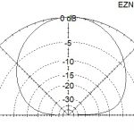
With each the dipole leg headed off at a 45 degree angle to its support as shown above, it becomes an Inverted Inverted Vee; I call it the I^2V. That antenna radiates with a major lobe straight up as you might expect, perfect for local/regional comms via NVIS. See its elevation plot below.
The I^2V presents an SWR of around 3:1, easy for my military field sets but also for a “50 ohm” radio with some matching help if your radio needs it. It is also within 2 db of omnidirectional at a 20 degree takeoff angle, even better at higher angles. Its a useful antenna, especially for regional work.

Inv^2 Vee The Inverted Inverted Vee
On Baluns in the Boonies: Of course, running a balanced antenna like a dipole and feeding it with unbalanced feedline like coax calls for a balun or at least a current choke at the antenna/feedline connection. Good engineering practice. However I have rarely used them and no-balun, coax fed dipoles seem to work as expected with respect to directionality, RF on the transmitter chassis, SWR etc.
In the boonies, unwanted feedline radiation (if there even is any) is usually not an issue; try to keep the coax at right angles to the antenna for as far as you can, to reduce that. Once again, the guy on the receiving end will not notice the difference. I like to keep it simple.

Boonie Dipole – no Balun
Above: Another day in the mountains….The NVIS “Cloud Warmer” as deployed.
Of course for wire antennas at a fixed installation, open-wire ladder or “window” line all the way back to the transmitter is your best choice to minimize line losses with a balanced antenna (and then it must be properly coupled to the transmitter). However that stuff is clumsy, difficult to transport in a small pack, highly visible and generally impractical for a portable, field antenna system.
Further, resonant dipoles generally outperform the purpose-designed “long” wire or vertical HF antennas supplied with military field radios such as the AT-101, “Hank”, other Inverted L antennas or verticals like the AT-1011. (Verticals radiate equally poorly in every direction and require a big, low impedance ground system to achieve any reasonable efficiency.)
Both wire types need two supports but the balanced dipoles do not require a ground or ground wire array like the Inverted L’s or slant wire antennas. Simpler setup for the same effective radiated power and the dipoles don’t waste skywave power on a vertically polarized component like an Inverted L does. Also, less probability of an interference field between each polarization mode which causes holes in your coverage pattern.
HF Verticals are great if you only have to operate while moving in a vehicle, if you don’t need to communicate within a 300 km radius or so (beyond ground wave.) or if you only have 1 square foot available for your Antenna Farm.
End-fed wires? They must be great; everyone is selling them! Meh.
The generic End Fed Wire and the End Fed Half Wave (EFHW) is a special case of those. They are all the rage these days, and as with any conductor up in the air, they will produce contacts. Easy and relatively simple to deploy, they warrant some discussion. My experience/analysis here: N6CC EFHW Wire Antennas
My kit has sufficient wire for employing end-fed wire antennas occasionally – if I am lazy, in a hurry or only have one support available. They can be simple to rig in a field situation but are generally my last choice especially if more than 1/4 wavelength long.
The Low Dipole with reflector: To enhance NVIS radiation “straight up” for regional comms, it’s useful to deploy a half wave wire in the near-field, on the ground under the half wave dipole to serve as a reflector. Theory and modeling indicates it should add 2-3 dBd gain versus a simple dipole over “average/poor” soils. Wire conducts better than dirt!
Absent an instrumented antenna test range it is difficult for me to perform an “A-B” comparison measurement due to QSB fading and the practical aspects of instantly adding/removing the wire! But definitely worth it, simple, seems to work in the field – I’ll take it! The wire should be about 5% longer than half wavelength to enhance the reflection effect.
A 2-element directional “Yagi” array pointed “up”. What’s not to like?
The ends should be insulated and away from dry vegetation. The ends are high impedance points and will see high voltage; a possible ignition point in dry grass etc if you are running high power levels. Below: Two examples of ground reflector wires; one insulated, the other bare stranded wire on an RL-29 reel with clips for the end insulators:

Dipole ground reflector wire
These are actually for laying on the ground directly under a halfwave dipole antenna to reinforce ground-bounce; in this case cut for a half wavelength + on the 3.55 mc CW band.
When the dipole is erected 0.25 wavelength (can be a little lower at the expense of gain) above ground it produces a strong signal up at high angles due to ground-bounce for regional NVIS coverage. These low-loss ground wires enhance the in-phase ground-bounce necessary for even more effective radiation at high angles.
Another significant advantage of this technique for regional comms is that the low dipole is quiet during receiving. Quiet since it has low gain at low signal arrival angles. So it can reject interference from very distant stations and especially atmospheric static crashes from distant, multi-megawatt lightning activity near the tropics. Obviously these advantages make it a poor choice for “DX” work beyond 500+ km or so. Not my target.
Verticals for regional comms? Forget those fancy military ground-mounted vertical HF antennas/tuners unless you want to work really long range, omnidirectional “DX” via F1/F2 refraction or just local groundwave stuff. Verticals are terrible for “short skip” regional comms from say, 20 miles through a few hundred miles out via NVIS. Verticals produce a deep NULL straight up – exactly what you DON’T want for medium ranges.
Verticals are also comparatively noisy since man-made noise is primarily vertically polarized as is the noise from distant, multi megawatt lightning strikes. QRN. Your worst-case antenna unless you are mobile or constrained by real estate etc. (If you want to work long-range “DX”, you are much better off with a horizontal dipole at a half-wavelength high anyway.)
However, the above observations are about effectiveness of communications on frequencies within narrowly defined limits. Specifically in my application for regional (not “DX”), few hundred mile coverage out from remote locations like campsites, vacation hideaways and even my home base. If you want to operate with strictly / only military issued gear for the sake of “the experience” or authenticity (I also do that routinely), go for it !! It’s supposed to be fun now!
Note: Some really well designed field evaluations were done by the US Army in Panama in 1963. It addressed the issue of short radio ranges in jungle environments. The HF portions of those experiments contrasted the AN/TRC-77 with the AN/GRC-19 utilizing different antenna types in different configurations.
Slant wires, verticals/whips, dipoles, inverted dipoles, wires in the tree canopy etc were carefully evaluated. Short answer: The low horizontal dipole was overall most effective. An interesting read: Interim Report on Tactical Jungle Communications Study. (Reference 87) Lessons learned also apply in tactical deployments outside of purely jungle areas.
Resonant dipoles deliver high performance, are cheap, simple, lightweight, easily “home made”and compact for storage and transport. A rare case in life where the simplest, cheapest solution is also the most effective all-around. Since you get to pick the field deployment site (supports availability/orientation) you can also deliberately aim a dipole pattern for your target.
If you have no skills, no time, no wire, no tape measure, no tools or no imagination, you can purchase a “store-bought” dipole; a last resort that will work.
Stealthy dipoles? I have never been “caught” with antennas in the woods. (Forest Rangers don’t like anything in “their” trees.) “I’m just here camping”….
So “What’s the Best Antenna?”
It depends…….

PRC-74 Dipole as deployed
Above: The PRC-74 dipole assembly. Ready made insulator, terminal strip and wind-up fixture as deployed from trees. Simple, also works great on the GRC-9, RS-6 or GRC-109’s when in the field. This antenna stays packed with the GRC-109 system kit. It would be a no-brainer to duplicate this with scrap materials.

PRC-74 Dipole insulator
Close up view. The transmission line is about 25 feet of thin twin-lead. I’m guessing the feedline Z could be around 72 ohms. Pretty hard to see when deployed.

Plexiglass Dipole Center Insulator N6CC
Above: The home made plexiglass dipole center insulator as seen in my kit above. Deployed here at a mountain campsite with legs for 80 meters CW. One wire leg ran directly over our campfire, about 40 feet up, the coax quickly disappeared into the foliage. It was there for a 4 day weekend camping trip before any of my buddies even noticed it or the RG-58C/U feedline. Pretty stealthy.

Dipole center insulator – DIY
Any reasonable non-conducting scrap material will work as the center insulator; the DeLuxe version above with suitable connectors installed. Even with a 1 KW transmitter and assuming a 72 ohm antenna feedpoint impedance, the voltage between the elements at the center is less than 400 volts peak. At 100 watts it is 118 volts peak – almost anything made of plastic will work if it is strong enough. Plexiglas or lexan is ideal, dry wood will work in a pinch too. Or a dried out pine cone.

BNC-Banana Dipole Fixture
Above: Another off-the-shelf expedient, a Pomona 1296 shown here, or the preferred Pomona 1452 (female) BNC/Banana terminal adapter. The female Pomona 1452 (NSN 6625-00-102-5652) is preferred for a dipole fed by RG-58/U coax with an existing BNC male connector already attached. Otherwise you will need a “double barrel” adapter as shown above.
This can work well and is simple and small. However the RG-58/U can pull out of the BNC cable connector if the feedline is too long/heavy. The feedline may need some strain relief at the connector for long runs back to the radio. A Prusik knot is your friend.

DIY Antenna Matching Unit – N6CC Mobile
Above: Although not really “portable”, here is my home brew mobile antenna impedance matching / patch panel unit. Built on plexiglass panels and permanently mounted in the Bronco it can select either the TS-50 Ricebox, PRC-47, the GRC-9 or any other installed HF radio for fixed-portable operation. It can also select either the 14′ (to the tip) whip on the rear bumper or an external SO-239 antenna jack for fixed-portable operation.
It uses large-spacing Mil-Spec variable capacitors and AirDux coils and is configurable as an L network or a CLC Tee network as needed. The seemingly odd knife switches are excellent for high voltage – high current RF switching tasks. Having a mobile antenna capability is important in addition to pure “portable” ops:
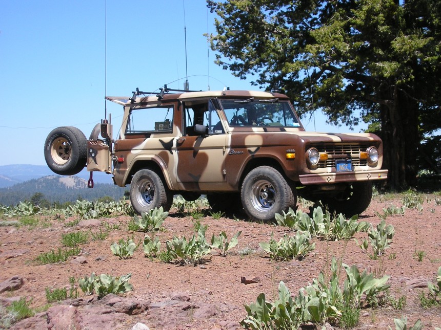
Mobile Tactical Antennas
Above: My mobile setup when operating mobile or fixed-portable. Antennas include an AM-FM broadcast radio antenna, 1.8-30 Mc center-loaded HF whip, 51 Mc Whip, 28/27 Mc whip, GPS antenna under a radome on roof, 145 Mc 5/8 wave whip and VHF/UHF scanner whip. Also included, and connected to the impedance matching device pictured above is an HF slant wire for regional NVIS comms while stationary. That wire is seen just touching the top of the spare tire in the photo. I also have visible and infra-red strobes available for signalling. The homebrew matching circuit permits operation on any authorized frequency I could need to use. From this mountain top, I have it covered.
The “tuner” permits switching between Hi/Lo Z transformation modes, radios, antennas and additional fixed HV doorknob capacitors. This is accomplished with an otherwise odd application for knife switches that are excellent for handling the high RF voltages and currents that are present. As such the coulpler can handle more power than I can generate – but at the same time operate in thin mountain air where corona discharge and breakdown can occur. It even includes a small NE-51 neon lamp across the input terminals to indicate full power transfer as well as a modulation/carrier indicator – very handy, especially at night.
Thankfully, and by design, nothing “automatic” here, it is pretty bullet proof, and will match almost anything in my portable field antenna kit as well.
————————–
Back to simple, quick and dirty. Running a wire up into a nearby tree and two “counterpoise” wires laying on the ground makes it happen for this AN/TRC-77 CW transceiver. This configuration is “per” the TRC-77 manual. Let’s see if it works well.

AN/TRC-77 driving the antenna
Above: The radiating element here is a 25 foot long, bare copper stranded “slant wire” up into a tree. The counterpoise consists of two 50 foot pieces of WD-1/TT infantry field telephone wires connected to the set’s Ground post. The ground wires are spread about 90 degrees apart. That insulated wire has 3 steel strands for strength and 4 copper strands for high conductivity. The steel strands make it springy – it remembers how it was last coiled up. But it makes excellent antenna or radial ground wires.
Here, testing the 10 watt transmitter on the 40 meter ham band. My first contact with this antenna was KF6GC on CW, a 178 mile shot in mid-day. This antenna system goes on the air quickly with minimal effort. It works OK, even for a slant-wire; a dipole is significantly better although harder to deploy. The Wonderful World of Tradeoffs.
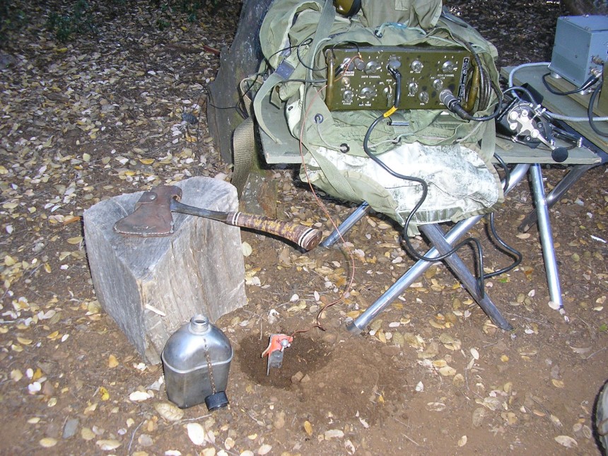
Field Expedient HF transceiver ground connection
Above: Although the ground radial wires are necessary for the efficient operation of an unbalanced “Bush Antenna” like that, this particular deployment also needed an additional “ground” to keep RF off the chassis while working on 3560 kc. The soil was particularly dry. In this case, the 18″ metal tent stake with the paint sanded off; keep it wet and add a little salt from your C-Rats or MRE to improve soil conductivity – it cured the problem here.

Tent Stake Ground Rod
Another handy (essential) device for field antennas is the “Radioman’s Helper“. This is a two-piece, 15 foot bamboo pole made by slipping a smaller diameter section into a larger one, with a hose clamp to keep them together.
A mangled piece of a wire coat hanger “S” hook on the top end is very handy for placing or routing antenna wires up into trees, around branches or connecting a halyard loop to a nail high up on a building, etc. The “S” hook allows you to push wire up or pull wire down as needed. The pole is also essential for grabbing the sling-weight which often doesn’t (rarely) make it down though tree branches to within reach…

Radioman’s Helper – Bamboo pole
The smaller end of the left “hook” piece slides into the larger “handle” slotted end, secured with the hose clamp. I consider this 15 foot pole to be an essential tool for stringing wire antennas in trees. Rides on the roof rack on trips.
In the below case the pole is lashed to a “support of opportunity” to hold up one end of the TRC-77 slant wire antenna. Or just jam it down a local gopher hole. Another mount is to just hammer a short piece of re-bar or concrete form-stake into the ground and slip the large (open) end of the pole over it. Self supporting, strong enough. Very handy:
Bamboo “Radio Man’s Helper”
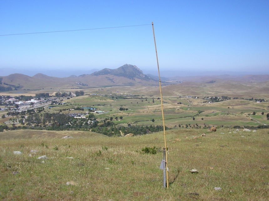
Above: The Radio Man’s Helper, here deployed as an expedient mast on this tree-less hilltop. This antenna, on this site, with the 10 watt TRC-77 operating on CW is easily capable of local and cross-continent contacts. Day or night.
You can use the bamboo pole along with the usual dipole parts from the kit to build a multi band dipole antenna array suitable for NVIS propagation. The bamboo bottom section is now reinforced with duct tape. Note the color-coded wire element attachment snap swivels:
Gray = 8 for 80 meters, Blue = 6 for 60 meters, Yellow = 4 for 40 meters.

Bamboo NVIS Antenna Kit
Just hammer a steel stake or piece of re-bar into the ground, slide the big end of the bamboo pole over it. This will hold it vertically after you connect and deploy the 1, 2 or 3 resonant dipoles in parallel from the feed point insulator out to the ends. Insulate and secured the far ends via nylon line and 10″ nail spikes for guy anchors. You can also run a half wave ground reflector wire under the dipole(s) to enhance the vertical gain if the soil is particularly dry/poor.

Bamboo NVIS Antenna Feedpoint
The feed point uses an old Budwig dipole center insulator hanging on the hook; it’s strong enough. Tie the wires at the insulator holes then connect them via the red/black binding posts to the SO-239 coax connector. Ready to attach the dipole legs, then stand it up.

Bamboo Mast base anchor
Just slide the bamboo over this concrete-form stake. A short piece of re-bar is also good.

The bamboo Radioman’s Helper makes a handy, light weight, easy to deploy NVIS antenna mast where there are no trees or other supports available to hold up wire antennas. Here on the “antenna test range” awaiting attachment of the dipole legs for 80,60 and 40 meters.
(You can also use it to find True North, determine local time or, with a time-tick from WWV, determine your longitude! But that’s another story.)
The Antenna Atlatl: Based upon the ancient spear-launching device (the lever). Just slide the launch weight inside the foot-long hollow end of the larger bamboo pole.

Antenna Launch Atlatl
As with a surf casting fishing pole, aim for your target tree and whip the end forward. You can easily throw an 8 ounce sinker 100 meters or more. With some practice it’s easy to get it 30 meters up into a tall tree. Multi-use antenna tool!
For more information about using this kit for building practical field antennas including terminated Vee’s and vertical rhombics, see Field Expedient Antennas
It includes information on making field expedient termination resistors from available materials.
For more ideas on how to employ stealthy antennas, take a look here:Stealthy/Covert Antennas
For further reading (or a good place to start) is the US Marine Corps Field Antenna Handbook MCRP 6-22D, Reference 88. For a more technical dive into the theory, practice and construction the ARRL Antenna Handbook is excellent.
Tim,
Great antenna kit! I am a firm believer in HF dipoles as the simplest, cheapest and most effective field antennas. I don’t try to get them up high, since I usually work 80m NVIS when I’m “cabin camping”. (Besides, I throw like a girl). I do use a gin pole made of MS-116 and MS-117 mast sections with a pulley on the end to hoist a wire into a tree. I like to make reel-out dipoles. My first one was made from two hand-crank antenna wire reels from the famous AN/CRT-3 “Gibson Girl” liferaft transmitter. Later versions used the more readily-available camper’s clotheslines and carpenter’s chalk line reels. For heavier dipoles, I did find an online source of genuine MIL-spec reels. Just add your choice of wire. (The same source also carries new, preserved 1967 vintage magnetic headphones, much better for CW than the modern hi-fi ‘phones).
73,
Bob WB2VUF
I like the 1:1 SWR comment! My Elmer K6VHP(SK) beat that into me. In a pinch, I tune for minimum reflected power and call it good. The math only works in deep space………….hihi!
73 DE JIM K6FWT
Hi Jim – Yeah, maybe I’m a little hard on the Buddipole stuff. They are certainly well made and will work if you have absolutely no alternatives support-wise for simple wires. But antenna current – in the right place – does the work!
Nice QRZ site photo’s you have there – a neat TCS setup too. I like the hollow-state “glow” photo’s – very cool!
73 & thanks for visiting my site!
Have fun,,Tim
Greetings”
Looks like a great antenna kit to me. I’m oriented toward RG-8 mini coax because the loss is a little less than RG-58. I use brown #16 speaker wire for antenna elements (split into single strands). I use a 1:1 coaxial cable balun for balanced antennas. Seems to work a little better than direct connection. Use dipoles pretty much as you described for 3 to 50 MHz. Change elements depending on frequency. Use “Jungle”, expedient RC-292 antenna or vehicle magnetic mount antennas for 146 MHz or 440 MHz..
Again your system should work well and best of all its inexpensive.
Hi Dan – Well I agree – use of a balun on a simple dipole is certainly “good engineering practice” – I recommend it! The one I made for my PVC center insulator gizmo works fine, the SWR is as expected (low) and the pattern seems to be as predicted for a dipole. I also see that dipoles just simply fed with coax work fine for me and are simpler and lighter to put up in the field. I’m not sure a distant receiver would notice any difference, but reducing feedline radiation and local noise pickup would be degraded without the balun. That may be handy around the home QTH more so than out in the woods…
Also, the thin RG-8X type coax is good to use and it is lightweight. I use RG-58C/U because I had it around and it is lightweight and packs easily in a small coil. Loss-wise on the HF bands the difference between say RG-58 and RG-8X for a 100 foot transmission line would not be discernible at a distant receiver – propagation variations would probably dominate anyway if you did an A-B comparison test. Yep – the better coax is lower loss but to me, it’s not a practical difference for the kinds of HF antennas I rig and use in the boonies…VHF of course begins to be a different story.
Speaker wire is just fine and it is widely available – works great. (Isn’t copper wire crazy expensive these days? LOL)
Thanks for stopping by! It’s fun to play with this stuff – especially in the woods where I can put up better antennas than I can around the neighborhood here!
73, Tim
Good job and nice your project
hope see u on air
73
9w2li
Hi Azmie – Thanks for stopping by my website…
Have fun with your antenna experiments!
73, Tim
Tim,
Your website is one of the best I have ever seen!! I just want to thank you for all of your great ideas! I revisit this site all the time and I reread your posts. I now have my on commo blog and I hope it will be half as informative as yours. Thanks for your service!
73’s
Joe
Hi Joe – Thanks! and thanks for visiting, it has been a fun project…
Great site. I have learned a lot from it. I will be taking my test later this summer, of course I have learned the code and forgot it 3 times over the years, at least it’s not required, so I really have no excuses. Anyway, I am starting to accumulate supplies, radios, etc. I would like to put together a few of your kits. I realize most other guys would know from your list exactly what to do/buy, but any way you can give a little more specific information using little words for us newbies?
R/CJG
Hi Chuck – Thanks and good luck with your license study, it’s a great hobby. “Details” PM sent.
Thanks for visiting!
Tim
Hi Tim, thank you for sharing your excellent ideas! I’m setting up a go-kit and was trying to figure out something simple, lightweight and effective for antenna(s) and accessories… yours are the best ideas I’ve found so far!
73,
Marcelo W6EUH – XQ6BQ
Hi Marcelo – Glad you could find some of this to be interesting. It’s a fun aspect of the hobby – and useful….
Good luck with your kit! Practice makes perfect….
73, Tim
Hi Tim , just ran across your site after searching the Web for portable dipole antennas . I have recently purchased an Alinco DX-70th radio and am looking forward to using it while out and about in the outdoors, so now I am looking to make a few wire antennas and I really enjoyed reading through your website. I especially like how you differentiate between best case scenario and good enough .
Thanks for sharing .
73, Steve KD8VPT
Hi Steve – well thanks, hope you found some of it useful. As we all know, experimenting with antennas is fun and a good way to learn about both theory and empiricism. I guess I’ve found that simple and “good enough” often works just fine and the guy on the other end probably wouldn’t notice any difference anyway.
Ham radio is a great hobby and being outdoors is wonderful – and antennas live “in between” so they are an ideal place to play…
Have fun with your DX-70 and thanks for stopping by!
73, Tim
I have made a back pack radio using a Yeasu 857. I use it on RTX and it work well. Just obtained two PRC 1099’s and your site have given me some new ideas on getting in the field.
Thanks
73
Glenn
Hi Glenn – Yep – portable and field ops are fun and it puts radio to practical use. Good deal on those PRC-1099’s, very nice HF sets.
Glad you found some of this useful and thanks for visiting my site…
73, Tim
Tim
As a newer operator to the HF world, I enjoyed the thoroughness of this article. Learn something new everyday! I love tinkering and improving my diy 2m antennas. HF on the other hand has driven me mad. For transparency I do own a commercial Buddistick. Ran an older TS 50s then started using a FT 450 and as a noob, have had fun making contacts with my simple setup. OMISS 40m nets is pretty much all I do, time permitting. So the Buddistick and my radials never change. However, now that Santa got me a new Kenwood 480SAT and I am more of a portable user, I find the timing perfect that I found your article. An upcoming road trip with my son to some hills to test out the new radio has had me obsessed finding simple yet effective diy resonant antennas since i do not use a tuner.
Just wanted to share, and say thanks for an informative article.
73, Terry
Hi Terry – Thanks for visiting…I think wire HF antennas for portable ops work very well and are simple. Pretty much tried to make my point in the post – but no offense regarding the Buddipoles! haha. They are metal and can work.
I also have a TS-50 (in my truck) and I like it a lot but it shuts down if the antenna impedance is even a little “off”, so I use a simple (MFJ) CLC Tee tuner with it. Good portable combination, very forgiving with compromised antenna designs.
Have fun going portable! Tim
Want to purchase this kit. If possible, how much is it? And how can i?
Hi Jason – Thanks for stopping by. Well, the kit on my website is really a one-of-a-kind that I built for my own use. I posted it here to encourage others to build their own kits to enable their own field radio work. So unfortunately it’s not for sale (but all the parts are pretty much commercially available)..
Have fun – antenna experiments are fun and educational.. Tim
What are your thoughts on the off-center fed dipoles. I have a commercially made one that my Dad bought. It’s 90 feet on one side and 45 on the other and I think the balun is 9:1. The feed point is at 35′ with the ends at 10′ each. It seems to work OK except on 15M but does suffer from feedline radiation. I’ve installed a choke which did eliminate that problem……..
Hi Charles – Well they should work OK since they are basically lots of wire in the air, halfwave on 80 meters, (versus smaller, more compromised radiators). But why would one choose an OCF wire antenna over a naturally balanced dipole/doublet? A center (coax) fed dipole balun would be basically 1:1 (lower losses than a 9:1) and inherently somewhat immune to feedline coupling/radiation. I also think that an OCF wire antenna might be fussy about equipment grounding on some frequencies since it is unbalanced. Yours should work OK at that height as you have found, especially for NVIS on the lower HF bands. I’m pretty sure you need to use a tuner to work multiband…(non-resonant dipoles need them as well)..The only reason I think an OCF wire antenna would be used versus a center fed dipole might be due to supports availability requiring an asymmetric feed deployment.. But if it works, it works !!
Cheers & thanks for visiting my site…Tim
Update: Upon looking at the Buckmaster OCF-7 specs for this antenna I am puzzled. They show a pretty impressive VSWR versus Frequency graph showing low VSWR dips in the various ham bands. But how is this performance possible if they don’t state the feedline length for the test? n-halfwaves? The customer-supplied feedline will be a “random” length, thus becoming a random impedance transformer versus frequency. So the resulting VSWR/frequency performance will be random and entirely and dependent upon the feedline length – and not what their graph shows. Anyone know how this is done?
Great site and have to say I love your portable field antenna kit. I recently passed my tech and am currently studying for my general and would love to put a kit like this together for camping, hunting and general go bag use. I am new to building antennas but not to electronics and was hoping you could shoot me some more details to help this poor newbie build this great kit. Really appreciate all you do. Craig- KF0EEJ
Hi Craig – Well, Thanks & thanks for visiting….Glad to help, I hope you found some of this useful.
Do you have some specific questions that I did not address ? Just send me a PM or Comment.
Congrats on your new license – a fun, practical and very useful hobby awaits! Tim
Great kit!
It looks like you addressed just about everything necessary to successfully deploy portable antennas quickly and efficiently for all the popular HF bands. I always enjoy seeing what others come up with for their go kits. Lots of good ideas there… Excellent work!
Thanks for sharing
Steve -W9HH
Hi Steve – Thanks! Camping, ham radio, antenna experimentation and being “in touch” from very remote places is always fun – and practical!
Thanks for visiting my website..73, Tim
Hi Tim, I love your site and agree with other commentators that it is one of the best. I also love low HF dipoles, for all of the reasons you’ve noted. I’m very interested in trying the near-field, on-the-ground reflector. The only thing that puzzles me is where to connect the ground wire reflector — rig chassis, coax, or…? Sorry for the Muppet Question, but thanks a ton! 73 Ern KI5QYC
Hi Ern – Thanks for visiting!
In the example of a horizontal, halfwave dipole, just place the half wavelength reflector wire directly under the dipole – and don’t connect it to the radio. The reflector will have high impedance/voltage at the ends, high current in the middle so no other connection is needed. The operative idea is that wire is a better conductor (and has higher Q) that soil.
Hard to tell the gain improvement without an instrumented antenna test range but it makes sense…Tim