
UPDATED 2/5/2022, Stay tuned, Under Construction
A friend in Colorado recently gave me a veteran RT-794B/PRC-74 because he wanted it to go to a “good home”. I shall try… Many thanks to Steve! In return, and as promised, I will write up my observations, research and future field use as I go along.. More to follow.
This is the main Receiver-Transmitter unit, becoming the AN/PRC-74B when all parts are included.

AN/PRC-74 SSB/CW Manpack Transceiver
Basic Specifications: (from FM24-24, December 1983)
Frequency Range . . . . . . . . . . . . . . . . 2.0 to 11.999 MHz (AN/PRC-74 and AN/PRC-74A);
2.0 to 17.999 MHz (AN/PRC-74B and AN/PRC-74C)
Planning Range . . . . . . . . . . . . . . . . . . . . 40 km (25 mi) ground wave; refer to sky wave
propagation chart to determine medium range
Number of Channels . . . . . . . . . . . . . . . . . . . 10,000 spaced every 1 kHz (AN/PRC-74 and
AN/PRC-74A); 16,000 spaced every 1 kHz (AN/PRC-74B and AN/PRC-74C)
Power Input . . . . . . . . . . . . . . . . . . . . . 10.5 to 17 V DC, 12 to 31 V DC or 110/220 V AC
Power Source . . . . . . . . . . . . . . . . . . . . . Battery (BA-30, 70 each or BB-418/U, 10 each);
vehicle power system (requires PP-4514/PRC-74); any appropriate AC power source (requires use of PP-4514/PRC-74)
Power Output . . . . . . . . . . . . . . . . . . . . . . . . . . . . . . . . . . . …. . . ..15 W PEP
Antenna . . . . . . . . . . . . . . . . . . . . . . . . . . . . . . AS-1887/PRC-74, slanted wire and dipole
Tuning . . . . . . . . . . . . . . . . . . . . . . . . . . . . . . . . . . . . .. . . . . . . . . . Detent
Type of service . . . . . . . . . . . . . . . . . . . . . . . . . . . . . . . . . . . . . . . -3 K00J3E, 100HA1A
Weight . . . . . . . . . . . . . . . . . . . . . . . . . . . . . 18.8 kg (41.5 lb) with dry Battery BA-4386/U,
two each; 13.4 kg (29.5 lb) with wet Battery BB-418/U, 10 each; 22.7 kg (50 lb) with PP-4514/PRC-74
Operational history: Under development
I’ve done some preliminary research on its history and usage. It didn’t really replace any specific radio per-se; the new requirement was for a portable HF voice radio that could be used while being carried.
That is something previous HF field radios could not do since the BC-611 Handy Talkie and the Navy MAB in WWII. A side mounted, tunable whip antenna made that possible for the PRC-74, it would also work with the usual wire antennas for fixed-portable operation.
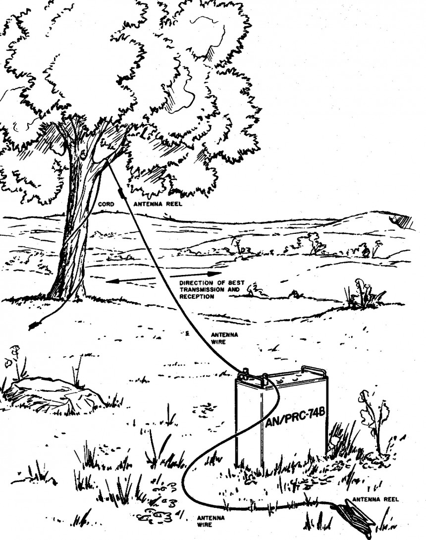
PRC-74 Bush Antenna
The first fifteen PRC-74’s were issued to units of the Military Assistance Command Vietnam – Studies and Observations Group (MACV-SOG) in Vietnam in November and December 1966. They were then widely used by Special Forces there. This included SAAT teams whose unconventional warfare (U/W) mission was to infiltrate deep into enemy held territory to locate and rescue downed pilots or prisoners held by the North Vietnamese communists or their Viet Cong dupes.
Those missions required portable, long range HF radio; CW being the most efficient mode of choice. However the assigned radio personnel were either unqualified or otherwise not proficient in CW. So a special 11 week CW school was set up at the airborne training site at Camp Long Tranh to get these and other SF radio operators qualified on an essential skill for their missions (Reference 1 MACV-SOG Communications).
The AN/PRC-74 was nominally sourced as an interim stopgap for the AN/PRC-70 (which had not even appeared yet due to significant development delays). The AN/PRC-70, in turn, was intended to have replaced the AN/GRC-109 HF radio in some SF applications, although the GRC-109 could not be operated while being carried and was CW-transmit only.
The CW and SSB voice PRC-74 provided a new capability in select man pack applications while the PRC-70 was still experiencing design problems. (Reference 1). The PRC-70 would provide HF SSB voice and CW but also VHF FM voice in one (heavy) package. As a consequence, note the out-of-sequence Model numbering; the 74 preceding the 70 in deployment.
The PRC-74 portable transceiver was ostensibly intended to provide beyond line-of-sight communications for U.S. Army long range reconn, air assault, Special Forces and other “mudborne” US Army units (FM24-24) .
Below are some Special Forces soldiers training with the AN/PRC-74 at Ft. Bragg, date unknown. This photo appeared in a US Army Special Operations Forces historical publication, (Reference 105). The caption mis-states that the RTO is transmitting a message in Morse code with the AN/PRC-74. He is actually holding an M-80/U microphone, not a CW key. Close enough.
No whip antenna attached, the dipole feed line appears to be in the foreground.

PRC-74 at Ft. Bragg
Not sure what’s going on here. The barefoot guy with the long hair and headset doesn’t quite fit the picture. He DOES have what might be a very well-worn P-38 can opener on his dog tag chain. (HaHa! Go NAVY!) Maybe he is a Hughes Tech Rep. these days. Or a Partisan from the village Pizza shop being trained in guerilla comms? US Army Photo.
There was the basic unlettered, initial issue AN/PRC-74 that covered 2 – 12 Mc and then a similar “A” model; the B version that covered 2 – 17.999 Mc and also was interoperable with the GRA-71 code burst morse keyer. The C model came still later with minor improvements to the B version. It was adapted from a “commercial” transceiver (Model HC-162) made by Hughes Corporation to fulfill the Special Forces requirement. It became the AN/PRC-74, the first frequency synthesized HF manpack SSB/CW radio set fielded by the US.
It was eventually superseded “on paper” by the PRC-70 that had wider HF frequency coverage and also included VHF FM voice. Good idea, badly executed and some of the SF guys that I have read preferred the PRC-74 which they thought was quite good – although a battery hog and sometimes had problems with the heat and humidity.
The manpack HF function of both the PRC-74 and PRC-70 was later replaced by the HF-only AN/PRC-104, still in use today. There doesn’t seem to be many PRC-70’s around as far as I can tell (I know of one being used by a Ham). Virtually nothing about the PRC-70 in the historical record.
Incidentally, Tadiran also made (or modified/re-badged) some PRC-74’s known as the “Transceiver RT-794T”. Oddly, those included an AM (AME) capability.
This particular example:
What an adventure this one has been! Seems this radio may have been that unfortunate one that the depot maintenance guys never got working – so they pulled any good modules from it and replaced them with ones that were too difficult to troubleshoot. Enter FrankenRadio….It happens, get the radios back out to the troops – work on the “Too Hard” ones later on… eventually “beyond economic repair” and scrapped.
None of the module serial numbers match each other or the chassis, so this one has been “through the mill”. It is a “B” model, 2 – 17.999 MC, wired for use with the GRA-71 code burst keyer. The particular example in this post was built in 1968. The PA module was overhauled by the Sacramento Army Depot in 1982.

AN/PRC-74B chassis wiring, typical
Above: Showing typical wiring on the underside of the chassis. Note the use of terminal strips and spade lugs to connect to the main wiring harness versus multi pin connectors. (At least these give you access to some power supply and control voltages.) That’s the RF module in the center, the transmitter RF power amplifier on the right.
I had to replace 4 transistors and 2 diodes on the gain control board. There was evidence of some Blowtorch Soldering…..The RF stages and synthesizer were badly misaligned, So now the receiver works OK, better than 1 microvolt sensitivity. But the transmitter power amplifier is not working and the ALC feedback loop that it drives is also whacky (and somewhat complex, the manual is not particularly helpful) . Much more investigating to be done there…

PRC-74B Power Amp Testing
Above: Typical bench project; locating where the transmit signal stops going. Looks like it might be bad PA transistors. I hate it when that happens.
Another problem was the mechanism that drives the 4 position band switch from the front panel. The manual advises that “the band switch mechanism is properly set if the band switch changes from Band 1 to Band 2 when the MC selector knob is moved from position 2 to 3”.
Thanks, that was helpful…. The MC knob has an extended lever to permit the operator to exert some additional torque while rotating these cams, pawls, gears and switches. The parts were sufficiently worn that it usually jammed during rotation. There is just enough gear backlash coupled with worn cams and pawls that it doesn’t work reliably so I just had to mechanically disabled it by removing the drive gear. I can change between the four major bands with a screwdriver for now…
Another bizarre problem: The wire that connects the front panel antenna Ground post to the chassis (actually to the PA module chassis) was broken – but the teflon insulation was intact OVER the break. Whiskey Tango Foxtrot? That almost sounds like a fault injected into a students radio to see if they could find the problem while in training to maintain this set. Hmmmmm.
The Manual: TM11-5820-590-35-1. Not particularly good, it jumps around a lot, the sub system schematics are not near the associated text, the schematics are multi section – with the “down range” circuitry in the manual ahead of the their associated input stages. Grrr. Very poorly organized, looks like a “rush job” to get these sets fielded.
A more immediate concern is that the radio cannot be aligned as a fully operational radio. Each module must be removed, powered up by up to 3 independent power supplies, some external adjustment pots, inputs provided as specified, outputs loaded properly and measurements made while adjusting. Makes sense for a module assembly line but tough to get a complete radio figured out and tuned up at Depot level shops, not to mention field repair sites.
Very few signal test points are available while the modules are installed in the chassis. The fault isolation procedures in the manual (and the PRM-31 Test Set) will help identify a bad module assembly but it offers little information needed to identify problems at the component level. Back to the Depot or further up. Physically getting at many components buried in there is tough anyway.
I’ve spent about 100 hours on it so far but it’s a challenge – I am learning a lot along the way and that’s the “fun” part. Fortunately no unobtanium IC’s, microprocessors, LCD displays etc. All straightforward mid-1960’s analog transistor design. Even lots of NPN silicon transistors among the germanium PNP ones. Many are easy to replace as necessary…Except those TO-61 stud-mount PA transistors that sport a Hughes in-house part number. Probably a stock JAN type of the era, but graded out by Hughes for similar performance in the push/pull output stage. Someone suggested 2N2876’s. Hmmm.
Maybe the thing is to “Ham-mer” this set and design a new PA stage using modern 12 volt silicon RF transistors rated for linear P-P service and with adequate gain and frequency response. Fit it inside the existing module, disable the 40 VDC power supply oscillator and feed it directly from 12 V. Some impedance matching and bias changes would be needed but could be simple enough. Except for the package/heat sink and volumetric requirements. I have not found any modern stud-mount transistors that will do the job these days.
UPDATE 12/6/21: After some thought I have installed two 2SC2078 NPN silicon transistors in the PA module. They came from scrapped CB radios and should work fine as replacement transistors along with some necessary associated changes. I rewired the stage for +12 VDC on the collectors (vs 40 volts). However the PA driver stage has always been unstable so I have to fix that first before I continue testing the new PA transistors. See my note in the Comments section below. This project is moving – but very slowly…
Functionally, the radio’s kind of like a mini PRC-47 with extended frequency coverage but without the 100 watt power level function. One significant issue for use on the ham bands is the way it generates a CW signal. Like many SSB radios, this is accomplished by injecting a keyed audio tone into the mic circuit – which causes that tone to appear as a sideband (above) the suppressed carrier frequency, the indicated “Window” frequency.
Standard stuff, but the PRC-74 uses a 2 kc +/- audio tone to generate the CW signal. Will be very confusing to the receiving station as well as trying to figure out which frequency your signal actually is on. The Collins KWM-2 (FRC-93) does essentially the same thing with a 1.7 kc (appx) signal. Had those sets used an 800 cps (+/-) tone instead, they would now be “forward compatible” with modern ham gear. HiHi.
Some of these sets seem to be around but I think they are not particularly attractive to most hams as they are only USB. Amateur radio convention has chosen LSB operation on the 75 and 40 meter phone bands. Of course USB operation on those bands is perfectly legal although many “appliance operators” these days seem to think otherwise.
I understand that “converting” one of these sets to LSB is quite invasive. Probably not widely done. Of course the basic model “plain” and “A” versions would not operate above 12 mc so they would be even less interesting to many Hams.
On Primary power: In addition to the stock wet-cell battery there was an alternate manpack battery box which included holders for 70 D Cell batteries. Wow…A pragmatic logistics-supply consideration… The receiver only draws 95 mA.
UPDATE: I just received this NIB Battery Box and whip antenna clamp from Mark K1HF as a very kind donation to “The Cause”. This CY-6121/PRC-74 was as “NIB” (New In the Box) as you can get – it was still in the original vapor proof packaging from July 1971. Many Thanks Mark!! It’s gone to a Good Home.
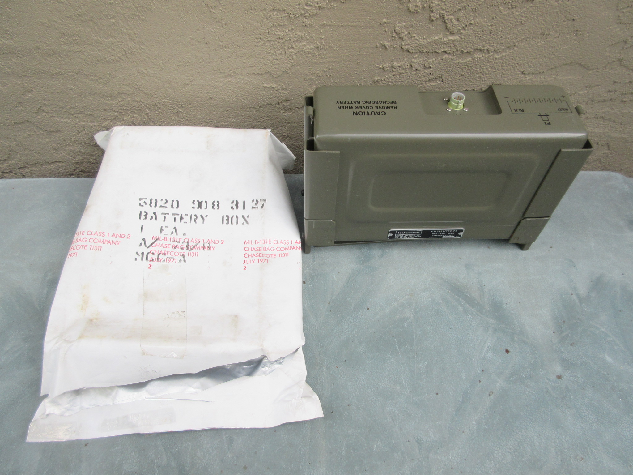
NIB CY-6121/PRC-74 in original packaging
By the way, Mark is looking for a PRC-74 RT as he gathers all the accessories. Please help him out if you can, or if you have a lead!

CY-6121/PRC-74 Battery Box
A rather complex “box”, it contains the inner clamp assembly for ten BB-418/U wet cell NiCad batteries. (The “/U” denoting Universal application) These batteries do not fill the entire volume of the box as you can see. This probably indicates the requirement to use this existing battery type (also used in the AN/TRC-77) even though the footprint of the RT could have accommodated somewhat larger batteries of a different geometry.
There is another battery box for this set, the CY-6314/PRC-74. It was designed for use with two BA-386/4386 dry cells, a battery also used with the AN/PRC-25. This CY-6121/PRC-74 sports a 1968 Contract date from Hughes.
Clipped to the RT, it makes for a rather large package, but like the earlier AN/PRC-10, it is proportionally quite thin, keeping the weight closer to the soldiers back. A “more comfortable” carrying arrangement when lashed to a standard packboard. (There is no issued web gear carrying harness for this set.) Also note the swing-out feet on the bottom of the battery box to facilitate standing the radio face-up. Also as seen on the AN/PRC-10. Good idea.

AN/PRC-74B Ready to Go
Above: A complete field package, ready to go with dipole/wire antennas. In my use, the battery box will accommodate two 12 volt rechargeable SLA gel cell batteries wired in parallel for operation. (That internal clamp assembly for the wet cells is removable). Note the different paint colors used.

PRC-74B with Whip Antenna Bracket
Above: The PRC-74B with the MT-3613/PRC-74 whip antenna bracket and an AT-271 three meter whip antenna installed to test the receiver. I need to find or fabricate an electro/mechanical equivalent for the AS-1887A loaded whip antenna. That M-80/U mic was standard issue for these sets although an H-189/U Handset is also appropriate.
I am using a 12 volt, 7 Amp-Hour SLA battery in the battery box; it works well. It will eventually have two batteries in parallel once I get the transmitter PA fixed.
A quick deployment to check the receiver performance at a campsite with other gear. Military Field Day EX 2019
It was in good company with the TRC-77 and TRC-88 as well as the PRC-25, all of the same era. We also included a GRA-6 field telephone system back to the CP with its VRC-7 and PRC-47 base radios. A pretty good Forward Operating Base setup in the bush. That little alarm clock is essential for making my Comm Windows from a campsite – too many distractions (like chow) going on.

PRC-74B Field Evaluation
——————————————————————————————————————-
Further work on the PA power output problem. Pull the module, power it externally, drive and load it properly, look around. Also look for any collateral damage caused by this – or something else that caused this short. That wattmeter still hasn’t moved off zero…. Embrace the Suck.

PRC-74B PA Transistors
As I feared, one of the PA transistors was shorted. Now to find suitable replacements or rough equivalents. That’s the dead one, laying on the pad.
The TM11-5820-590-35-1 maintenance manual dated July 1968 shows the 6 digit Hughes part number for these transistors as 703075. The one that failed in my set is stamped with TRW as the manufacturer and it has 7230128038C printed on the side .
However my PA module was overhauled in 1982 so that may be a newer number for a replacement, possibly better transistor. It is likely that those PA transistors were replaced during overhaul as they are apparently prone to failure. The tables also show that Depot level maintenance activity spares allowance is 20 transistors for each 100 radios. That suggests a high failure rate compared with other transistors in the radio. Those last 4 digits printed on the failed transistor may be a date code: 8038, the 38th week of 1980.
My PA module was overhauled by the Sacramento Army Depot so it is possible that a different (better, hopefully more robust) transistor was available (and installed) at that late date. Hard to say. The Federal Stock Number for the PA transistors is listed as 5961-999-7341. Manufacturer code 01281 which is TRW. Manual page B-40
Not knowing what performance parameters Hughes required for their “house numbered” parts, this will take some investigating via reverse engineering. Then finding available parts that would meet the as-built circuit requirements as well as the mechanical, stud-mount package. It’s tight in there.
One key parameter would be a pair with similar Beta’s or hfe performance, all other specs also being suitable, especially a high GBW product capability. Dissimilar Beta’s/hfe would cause bad waveform distortion in this push-pull output circuit which already has minimal harmonic filtering.
(See the note above regarding 2SC2078 “CB” radio PA transistors.)
More to follow….
I enjoy your articles/history lessons of the various mil commo gear. I am retired 31 years Army, the first 15 yrs as a Huey driver / instructor and the remainder as a PA/Flight Surgeon. Now I just collect the dues for all the years. It was a fun. I pulled out my old PRC-74B and dusted it off. Checking the internet I found your entry on this unit. I will put it on the air this week. It operated FB about 10 years ago on 20 meters. I thought since it was USB only and I did not want to mod it but keep it original that 60 meters would be the perfect band. I also have the GRC-109 and part of the GRC 9 set. My 74B is missing the ID plate, bummer. It did come from an SF unit, an A team, A-6 and shows the wear (abuse). When I bought it I bought a complete set (I think; haven’t inventoried them in a while) of NOS modules for this rig. If my radio plays well, I probably won’t need the modules but you never know. I had thought about selling them as a complete set but not sure yet. If you are interested, I will contact you first before I list them on ePay. TU 73, Mike
Thanks for checking in Mike. Will respond offline.
73 and thank you for your Service….
Tim
Hi Tim, glad to see contemporary interest in the 74s. I have one limping along and made several ssb and cw QSOs with mine today on 20 meters for old times sake in anticipation of getting out with the local radio club for a little QRP fest next Saturday.
Only big problem left with mine is I seem to consistently need to shift -1 kHz when transmitting on cw to get within the passband of guys using regular ham gear – not sure if that’s a design thing, or a tweak, but as they say, if it aint broke, don’t, so until that time comes, I ain’t. I just don’t call anyone I tune in at the 0 spot on the 1 kc dial 🙂
Good luck with yours.
73 Scott
Hi Tim,
I’ve got two of these up and running, unmodified, the original 74 and a B model like yours. I mainly use them on 20m and 60m USB since the CW implementation makes it difficult to use routinely.
Check around on ebay for the original battery boxes, they are around for not too unreasonable prices.
73 Roman
Hi Roman (and Scott) – Yes, that CW implementation with the 2000 cps (+/-) tone is cumbersome. I am still working on some ideas to fix the PA/ALC feedback loop in my set. Maybe build my own PA circuit to fit inside the stock module. Would allow me to use modern, 12 volt transistors and also eliminate the need for the 40 VDC oscillator PS in the transmitter. Once I get that all solved I will look for a battery box. They do seem to be “around”. Thanks for checking in..interesting, useful radio!
Hi – love seeing the radio. I used the 74B and C in the field while assigned to the 7th and 10th SFGA in the late 70’s early 80’s. Always CW of course. The radio was always reliable over the years that I used it and they were pushed hard in extreme cold and heat. I don’t miss carying it in my pack though.
Have fun with it!
Greg KC1CIC
Hi Greg – Thanks for checking in…Nothing like “ground truth” from a service user! I am going to dive into mine again when things slow down this winter – and figure out its problems. Looking forward to future camping trips with it…
Thanks for your service Soldier…
73, Tim
I just acquired an AN/PRC-74 yesterday at the Fall NEARFEST in Cow Hampshire. I need to get an antenna bracket for it and an M-80 and H-250 for set. The unit appears to be in good shape and needs the seller demonstrated on 60 Meters since the set remains unmodified for LSB. I used to have an AN/PRC-104 for MARS, etc. I used it to contact the EOC at Guard State HQ a couple of times. Due to unemployment, I sold it to make ends meet during the great recession in 2009/2010 until the Good Lord blessed me with a state gooberment job in public safety. I am looking forward to getting the beast on the air and making some CW contacts on 75 and 40 meters and maybe getting on 60 meters yet. I don’t know if I will modify it for LSB yet…
Hi John – Congrats! An interesting, very useful radio. The audio accessories are pretty common, the antenna parts less so. I think you will find that CW is not really viable due to the injected CW tone frequency. Your targets will probably chase you around the band trying to tune you in (or vice versa). Still, it will work. Good find!
Tim
HI Tim, did you ever obtain a battery box? Send me a message as I can help, good reading on the -74 thanks for taking the time to post the information on it.
Hi Mark. No, I still need a battery box for mine. Will contact VIASEPCOR.
Thanks,Tim
Hi Tim!
Thanks for your interesting article about the PRC-74.
I bought on ebay a PRC-74 A in 2005. I restaured and converted it for LSB and extended tune on transmit position, according to the Jim KARLOW (KA8TUR) publication.
Now, I enjoy it on 40 and 80 m band even it’s a bit difficult to tune sending and receiving to exactly the same frequency to the tens of hertz by. May be a problem of alignment. I got step by step the different accessories,(antenna, battery boxes…). If you want, I can send you pictures if you give me your e mail address.
73 and best regards
Cyrille, F4HUE
Hi Cyrille – Thanks for the note. I still need to get the transmitter power amplifier module on mine going but I look forward to playing with it. PM sent.
Merci !
Tim, N6CC
Hi Tim. Thanks for all the info. about these radios. I’m starting to collect old military radios and this is one of my first. I bought this and another one from ham operator who is liquidating his radio collection due to illness. Can’t wait to get this thing on the air after I upgrade to general class.
73’s
Chris KD9FMU
Hi Chris – Good deal on that pair of 74’s… An interesting radio with some good historical use behind the design. Yep – get on that General upgrade and have fun with them!
Thanks for stopping by…
Tim
Tim,
I really enjoy reading your discoveries as you troubleshoot these rigs. From tubes to transistors…you have some incredible insight. I have to chuckle while at the same time swearing under my breath when I read about broken wires inside the insulation. One of those moments when you question both your sanity and your ohmmeter. Wafer switch 180 degrees out? Good grief!
Btw…I ended up here after searching which radio was supported by the G-77/G hand crank generator. Of course, once I landed here I couldn’t resist reading the entire post while letting a few SOB expletives go as read about your discoveries. Wow. This is one for the record books.
Craig
N6CAV
Hi Craig – Thanks for checking in…Fixing the PA on this one is currently on the back burner but pretty close to “Next”. It’s a cool radio that will feel at home camping.
Another weird thing about the documentation – as I am sure you have noticed – is that the manual for its G-77/G hand generator is also the manual for the entirely different G-43 generator – but they don’t tell you that. Huh? Fun stuff…
Will we see you at Camp Plymouth next month? I should be there for a day, but no displays this time, too much going on around here..
73 & see ya around…Tim
Had a PRC 74C in Korea that I had previously purchased at PDO. I modified it to be more Ham Friendly, by removing 1 detent ball from each frequency knob control, and routed the antenna circuit out the bottom into a so239. Also put standard 12 volt lugs on the bottom, and powered it with a 12V 20 amp PS. I put a couple support legs near the face of it, and set it on the desk as a traditional radio.
I was lucky, and was able to put up a rhombic, using a 1/4 mile roll of WD1 commo wire for each leg. Worked West and East coast US daily on 20m with it. Sold it to another HL9 before heading stateside. Wasn’t the best radio to use in a area with lots of stereos, but lots of fun. Wish I had kept it.
Bruce wd4ngb
Hi Bruce – Thanks for the note! Ham Engineering – never occurred to me to remove the “detent” hardware…Not continuous tuning but it would “feel” like it..haha
… Yep you could make some noise with a big rhombic!!
Thanks for visiting my website & Thanks for your service..you’ve been around!
Tim
I operated the Prc-74B during my tenure 78-81 with 10th SFG Bad Toelz Germany
and again with 10th Group Ft Devens. We utilized this radio for CW Burst Transmissions
to our SFOB at 300GPM. A great and reliable radio
set..
I enjoyed reading all of the stories about the AN/PRC-74, hc-162. Now for the rest of the story: I did all of the mechanical design for those radios. They were done as a company funded project Headed up by a brilliant EE Roy Olson V.P. Hughes Aircraft Co. and Fred Fields,E.E. The first 25 AN/PRC-74’s sent to Vietnam were accompanied by John Steven, E.E. He supported and trained the Special Forces. For me it is wonderful to hear all of the wonderful stories and speculations
Hi William – Very cool! You sure got a lot of “stuff” into that small package. Sorry if I was a little hard on the switching gearsets! All done on a drafting table with pencils and T Squares…Excellent work! Rare skills these days with CADD doing all that interference checking “automatically”.
Thanks for your input and for stopping by!
Cheers, Tim
Love your website
We have a working PRC-74 with the LSB modification and have just recently acquired a battery box like yours. What batteries did you use in the end?
A fun radio for 80 and 40 meters
Thanks again,
Simon
Hi Simon – Good deal on the 74 /LSB. I have not used a radio with that modification but it’s obviously made it more useful for Hamming. Unfortunately the PA stage in mine is still awaiting more bench work to get it going – so I am only using a single 8AH Gel Cell to power it while just using the receiver. I think 2 of those batteries will fit in the box when the time comes. Heavy, but available!
Cheers and thanks for visiting my website..Tim
Great to read all the stories. I worked at Hughes Aircraft, Fullerton when these radios were manufactured. I remember seeing them stacked on the factory floor. Always wanted to own and operate one. So 3 years ago I had a chance to obtain one and bought one. Will be getting it on the air when I have more time. Have been procuring accessories. I probably knew people who assembled radios.
Hi Ed – Thanks for the note! You could really appreciate using one – with your connection to them! I’m a fan but mine still needs a lot of work..
Thanks for visiting my website, 73
Tim
Any luck on finding a replacement for the power output transistors? My manual shows 2N2887 (TRW) but no suppliers have them. The TO61, with isolated collector, may be a problem. May have to substitute another package and try to fit them in.
Hi Phil – The OEM parts seem to be scarce and finding a reasonably matched pair for P-P service is very unlikely. That package is also long obsolete. I have a pair of NPN Silicon 2SC2078’s from defunct CB radio PA outputs. TO-220 package and they should work just fine. There is room in there to mount them for heat sinking. I rewired the stage to power them with +12 volts Vcc (versus 40 VDC as original). The PA driver stage was also unstable for reasons yet unknown – and that stage also sets the PA bias current so some further investigation is needed before I can complete the mod. I’m confident it will work but getting at the driver stage components is tough – and that driver transistor is also unobtanium. The journey continues! Thanks for stopping by..Tim
Good afternoon,
I love this write up. I have a PRC-74B, the transistors are bad. I was curious how you got the Power Amplifier module out. I removed the captive screws on the bottom of the radio. I was curious if you could give me a little help.
Thank you
Wyatt
PM sent..Thanks for visiting!
HI Tim, I purchased another PRC-74B last fall to replace the one I sold, bought it from Dale who upgraded to a PRC-174. It was a bit challenging to complete another whole accessory kit but mission accomplished. I like the picture you recently added, not too many PRC-74 field pictures around.
73
Mark
K1HF
Hi Mark – OK on the new 74B, I am still working on mine, very slowly! Still has PA and PA driver issues. Yes – not many photos of the 74’s in service, I just recently found the one with the SF guys operating theirs in training. Cheers! Tim
Seem I have purchased another PRC-74. In the early stages of checking it out. The RX seems to be working ok. One note with the RF gain pot, one of the wires was hanging off, so very low audio output. Now resolved. The main frequency selection switch MC is not aligned correctly. I need a replacement plastic connector as it is worn out. The TX side is dead. So time to start testing.. Did you ever get the PA stuff sorted?
All the best.
Hi Simon – I think these are interesting sets that had seen a lot of service in combat. That said, I have found them difficult to troubleshoot due to dense packaging, few accessible test points and a manual that isn’t very well done. I found that the MC gearset in the band switch was very problematic in my set which I attributed to wear but it’s still kind of marginal to the task. I gave up as you may have read.
I have not finished the PA / PA Driver work, it has been set aside for a long time now, I need to get back to it to evaluate the CB PA transistors I installed but the driver also needs work first. It is very complex trying to provide temperature compensated PA base drive and base bias at the same time. Hughes also had issues with their own design; it went through at least 2 revisions. Confusing to troubleshoot.
Thanks for visiting and have fun with yours! Tim
Hi Tim.
thanks for sharing all the information with us. I like it to read your writings, especially as I am also using the green vintage radios.
Some time ago I had a GR-345 radio which is a copy of the PRC-74A .The GR-345 was made by Redifon in UK under license agreement for the European market. A number of this Redifon radios were delivered to Germany and used by the (formerly) “Federal Border Protection Forces (German : Bundesgrenzschutz). The radio’s German designation was “FuG 15” (Funkgerät 15 = Radio Set 15). It was mainly installed in 6-wheeled armored vehicles of the type “Saladin, together with an additional 100W amplifier (LV-100, an upgraded LV-80 as the German army used it with the GRC-9 radio set.). But back to the PRC-74 ….
I do not know if you are still struggling with the PA transistors and looking for replacements.
Probably I may be of some assistance. I still have spare transistors for a SEG-15 radio that has gone long time ago. I think, they will nicely fot your PRC-74. You may have a look to the datasheet: https://vikiwat.com/en/transistor-kt907-npn-60v-1a-13-5w-350mhz.html.
They are sold-out, but I am willing to donate my spares for your poor little PRC-74. You may feel free to send me a PM in this matter.
Hi Harald – Thank you so much for your kind offer on the PA transistors! I looked at the data sheet and I am sure they would be fine in the PRC-74… However I will decline the offer as the radio has other problems with the PA driver/bias stage and I think once I get that redesigned the “CB” PA transistors I have installed will probably work fine. So save your spares! Hard to find!
Also, thanks for the background on the FuG-15 and the history lesson on its application with the Bundesgrenzschutz – I looked it up, very interesting times for sure.
Thanks again and Danke for visiting! 73, Tim
I am curious as to how the 2SC2078’s will work. You will likely have to redesign the input/output networks to accommodate for the change in impedance when you go to 12v on the collector instead of 40.
I am about to try some 2N2876’s in my 74B here real soon. They do not have as high a dissipation as the 2n2887’s but they are all I got right now. I hope they work. It looks like my 74 lost a transistor recently.
Mosfets may be a better choice in the long run.
Hi Anthony – thanks for the note. Yup, running the PA at 12 volts will require some changes in I/O impedance matching too. The PRC-74 PA driver is complex, also controlling operating bias and responding to ALC signals as well. Mine is unstable so I have to investigate/fix that before I can further evaluate the CB PA transistors. I am sure I can get it to work but it’ been on the back burner for awhile…
Thanks for visiting! Tim
The PRC 74 series were very unique back in the late 60s through the 80s. While I was still on active duty, I acquired a few from PDO at Ft Campbell Ky around 1976. I was able to get 4 or 5 operational from combining parts.
I slightly modified one of them, and took it with me to Korea. I had a lot of fun with it talking to my buddies back in Tennessee.
Wish I still had it.
Bruce WD4NGB ex HL9JV, HL9TF, E30GA
Hi Bruce – Thanks! Ham ingenuity at its best! The PRC-74 is still a good radio. Thanks for your service and for visiting my website…
73, Tim
Very detailed article. Beautiful radio! Definitely a man’s tool.
I am wondering… What is the AWG size of the wire used for the original dipole legs of the PRC-74?
93 foot is a long length for each leg, and all that wire rolled up x 2 must be heavy…
Do you guys know what AWG size was originally used? Item number was 1560017. Have been looking with no luck finding out the original wire size.
The wire has to be strong enough to be able to hold the Dipole center, which is heavy, and also the weight of both legs of wire, when completely extended on its 186 ft. total length (93 ft each leg).
I guess, for ham radio use, no more than 30 ft is good for up to 40 meter band.
73
Rob
YS1RS
Hi Rob – Good question! I don’t know the AWG of the antenna wire and the manual does not address that. You’re right, it has to be fairly big to be strong enough to hold itself up when deployed to maximum length (@ 2.5 MHz). The fixture I have did not come with the wire and the “bobbins” that I got with the radio did not have the wire either, so nothing I can actually measure for you.
I have used # 18 and 16 for portable 80 meter dipoles and have not had problems in casual use. Since the lowest freq I can use is 3.5 MHz that seems to be good enough. For a permanent installation that I also did not have to carry around, I’d probably go with #14, it’s of course a tradeoff.
I looked at your QRZ page – we have a lot of common Ham interests and your work with UN and other aid assistance is an example for us all. Very well done and I wish you the best with your humanitarian efforts. Well done!
Saludo!! , Tim
Hola Tim!
Than you for your kind words.
Yes, we share many common interests.
One of them is the “green radios”.
Unfortunately, near to impossible for me to own one.
The closest I am to one is having the PRC-74 Dipole Antenna Fixture I bought from internet (hihi).
On the other side… I like to test new antennas, and since I already have the PRC-74 Dipole Fixture, wanted to complete the antenna set as much as close to the originals as possible.
That’s why I was asking.
I’ll go ahead with the info provided and have learning fun.
Every Antenna is a compromise. The military has tested them all, they have all the budget (your money) to test them all… and have made their choice.
Their choice has always been the old dipole.
Now, this one looks like a doublet, the radio has a tuner, so my interest in testing it.
In my case, after testing a bunch, the best antenna for portable ham radio, limited to the ham bands of course, has been the “Linked Dipole”. Again, the old trusty dipole but “fancy”.
Lots of useful info in your site Tim.
Thanks for sharing!
Saludos
73
Rob
YS1RS
Hi Rob – Well, you’re right. The PRC-74 dipole antenna is technically a “doublet” by virtue of its balanced feedline, a subset of dipoles I think. I am using it (and also coax-fed similar antennas) without a balun, good to use but not necessary for success. A linked dipole with intermediate insulators to adjust its length is very handy and simple.
Thanks for visiting and have fun! Tim
I still have two PRC-74B STASHED AWAY IN CANADA.
I WAS IN VIETNAM FOR FIVE YEARS AS A TELECOM ENGINEER AND USED TO USE A PRC-74 ON MY DINING ROOM TABLE RUN WITH A 12 HONDA BATTERY. ADD A 1 INCH RG 8 COAX TO THE PEAK OF MY DUPLEX FRENCH VILLA AT 100 FEET INTO A CB ANTENNA.
I WOULD RELIABLY WORK VSD6R. In Hong Kong and the Philippines, along with net control at 17.2 MHz in Ceylon
I had the second PRC-74 in my Samsonite briefcase which allowed me to communicate anywhere in Vietnam with Saigon base just needing a 12 V battery and a 30 foot tree to throw the loop over
I used to have conversations on a weekly basis with a Canadian aid worker worker in Uganda that was about 8000 miles away
Callsign was the VE7WU potable region 3
Hi Bill – Very cool…Yes, they are certainly both capable and versatile. I bet yours would work today once fired up!
Cheers and thanks for visiting,,,
Tim
Excellent and interesting website. You are quite correct that the PRC-74 was considered the “interim HF manpack radio”, and remained so until at least 1968. It was indeed intended as a temporary substitute, but for the AN/PRC-62, not the AN/PRC-70, which did not enter service until early 1980.
Development of the PRC-62, a highly advanced 20W 2-30 MHz manpack set, was begun in 1962 at RCA, and was expected to be available by late 1965. But when LBJ began the escalation of the Vietnam war in early ’65, it was realized that the PRC-62 (and its new magnesium battery) would not be ready. The military was caught without a modern HF SSB manpack transceiver–essential in the dense jumgles of southeast Asia–and so the Hughes HC-162 HF manpack, along with a few others, was considered as an interim radio. After a number of modifications, the HC-162 was qualified as AN/PRC-74 and placed in service with the expectation that the PRC-62 would eventually replace it. However, PRC-62 development continued to lag behind, and since the PRC-74, PRC-74A, and the extended frequency range PRC-74B were providing satisfactory service, PRC-62 development was eventually terminated and the radio is now largely forgotten. Only one PRC-62 set is known to exist today.
73,
John K9WT
Hi John – Thanks for that…I guess I had never heard of the PRC-62 in the literature but it seems it had the same issues as the PRC-70: Delayed delivery due to complex developmental issues with something that “promising”. Meanwhile the PRC-74(*) set soldiered on for a long time. “A Bird in Hand…”
Thanks,,Tim