Updated 6/25/2026:
US Marines of a Tactical Air Control Party with the First Marine Division in combat at the Chosin Reservoir operating an AN/GRC-9 transmitter-receiver. Hand cranked generator, cold weather, possibly watching Marine Corps Corsairs or Panthers rolling in on target: NK or ChiCom troops danger-close, Nov-Dec 1950. Hopefully it got REAL HOT for the Reds in short order. Field day of the highest order, not fun. But I bet it did the job…
Note the weapon (.50 Cal BMG) cleaning rod likely being used for a ground rod. They are using the older GN-58 hand generator; the receiver battery cord connector is visible. Note the plywood pack board below the “crankers” left leg, probably used to hump the radio or generator. The transmitter band switch appears to be set to Band 2 Master Oscillator (3.6 to 6.6 mc range.)
The Marine holding the T-17 mic and map is likely a pilot from the supporting Marine fighter squadron. The Marines found that this type of assignment produced the best air-ground, close air support coordination possible. Thanks guys. We remember. So do the South Koreans of the Republic of Korea.
Official USMC Photograph.

The GRC-9 was widely used during the Korean War. Below: Anti-communist North Korean partisans operating a GRC-9 and hand generator. They were highly motivated volunteers from the tens of thousands of Koreans who fled south after the communists seized control of the north. They were trained, equipped and advised by US Army Special Forces personnel to help liberate their homeland.
Self-named as “Donkey” units, they conducted raids and unconventional guerilla operations, taking the war back to the Chicom and North Korean communists in coastal North Korea.

A possible origin for their name was put forward by an early Donkey leader who stated “the generator of the [AN/GRC-9] radio looked like a Korean donkey or ass. When you crank the generator… you have to ride on the generator which looks like a rider on the back of a donkey.” (Reference 105).
Or possibly a simpler origin in the Korean word Dong-il (Leader). There were approximately 12,000 of them organized into 15 Donkey/Wolfpack units.
The GRC-9 in AM Voice mode would be quite effective for communicating with their Team Leopard base station on Paengnyŏng-do island off the west coast of North Korea. They had been trained in the use of One Time Pads.
“With voice transmissions ruled out by distances, communications specialists must rely on continuous wave radio operation, using the International Morse Code. They must be able to receive and transmit at the rate of 18 words per minute, perform maintenance up to Third Echelon and even build a working set out of parts at hand. Other team members must be able to work at least five words per minute and know how to set up and operate a radio. Workhorse of the Special Forces is still the dependable Angry Nine, officially the AN/GRC-9.”
Special Warfare U.S. Army, Chief of Information, U.S. Army 1962.
Later on, same problem, same idea, same radio, different place. Special Forces SGM Richard Epps Pegram, Jr. operates the GRC-9 while on patrol with South Vietnamese Montagnards. Sadly he was killed in a North Vietnamese Army attack on FOB-4 at Marble Mountain outside Da Nang 23 August 1968.

Above: The “GRC-9” at work with U.S. Army Special Forces and Vietnamese irregular forces fighting the North Vietnamese Army and Viet Cong communists in South Vietnam. Note the taller G-43 generator had replaced the GN-58 in this instance. Official Photograph, U.S. Army, August 8, 1964.
That image is from a Signal Corps film following a Special Forces patrol in Vietnam. The filmer or the person that entered the description in the National Archives file mis-identified the radio as the GRC-109. Incidentally, this 1964 photo is the only one I have found of US personnel using a GRC-9 in Vietnam. Well into obsolescence by then, the GRC-9’s were used by some US advisor personnel, especially early in our involvement.
Shown here, training and supporting an irregular forces patrol. However, the GRC-9 was widely used by the South Vietnamese government Civil Guard and Self-Defense Corps in the early 1960’s and also by ARVN units as well. The Viet Cong captured many of these radios and used them themselves.
The ChiCom Type 102E set is a repackaged, Chinese copy of the GRC-9 with a few changes. The North Vietnamese Army and VC used the Type 102E extensively in their assault on the south.
WWII? The AN/GRC-9 was a mid-late 1940’s development as an incremental improvement and replacement for the SCR-694/BC-1306 which itself was a replacement for the SCR-284/BC-654. Due to a lack of any actual deployment evidence to the contrary, it is widely understood that the GRC-9 did not see service in WWII as the war ended (VJ Day) before it was available or even ready for issue.
Here is an interesting shot of an SCR-694 being used by OSS Special Operations personnel on a rice paddy dike in China in 1945. It’s not known if it was before or after VJ day 1945.
That would indicate kind of a big change of direction on that date regarding our support of Mao & Co. against the Imperial Japanese Army or Chiang Kai-shek against the IJA AND Mao’s Communists shortly thereafter. (Reference 105)

A listing of war supply contracts (Reference 101) shows that a $90,000 contract, SC 921, was awarded to Crosley Corporation for GRC-9 radios in June 1944. It further shows that the “Contract Completion” was in January 1945. The report does not indicate what Contract Completion actually means. (Pertinent signatures obtained?)
However contract dates and subsequent procurement orders, production, receipt and fielding can be quite different. As WWII drew down many late war contracts were cancelled but we don’t know much about this contract or any associated, possible production run.
Other detailed US Army WWII procurement records were published by the Office of The Chief of Military History on 9 April 1952 (Reference 74). It shows that during 1940-1945 no procurement’s of the AN/GRC-9 were made during that time frame. To me, further evidence that they did not see service in WWII. The SCR-694 was being procured in 1944 and 1945 for 14,416 and 9,316 sets respectively to replace the SCR-284’s.
Orders were made in 1951 and 1952 to 4 different manufacturers of the GRC-9. These included Lewt, Crosley division of AVCO, Tele King and Hoffman Radio Corporation. Per unit prices varied from approximately $1,256 to $1,605 depending upon the year, manufacturer and contracted quantity. (Reference 78).
A total of 63,972 SCR-284 sets were procured during its run but none in 1945 as the SCR-694 took over and the end of the war was in sight.
Below is a photo of a 10th Special Forces Group LT showing their gear to a MGEN and some 5th Army and 82and Airborne officers in Bad Tölz Germany. Photo Undated. The LT has what might be the “Trojan Horse” insignia on his beret upon close examination. That insignia dates the photo as being taken sometime between December 1955 and 1962 when it was replaced. Army uniform trivia used to date photos!)

Notice GRC, C’s and Ski’s. (Plus an M-3 SMG and M-1/M2 Carbines). In this case the GRC is a GRC-9, left foreground. Present is the GN-58 hand generator along with the generator, antenna and accessories carrying bags BG-172, 174 and 175.
Incidentally, SF units like this could have also used the CIA’s RS-6 or RS-1 HF/CW sets in the 1950’s, then also available to US military. The RS-1 then being replaced by the Army’s nearly identical GRC-109 in the mid-1960’s. Ideal for these types of missions, they were better suited for man-portable Ops than the GRC-9 for many reasons.
The radio in the above photo is mis-identified in a subsequent Army Special Operations Forces historical publication as a GRC-109 just like the same mis-identification of the GRC-9 in the Vietnam photo above. US Army Photo. (Reference 105).
The GRC-9 did see widespread service during the Korean war and well into the 1960’s by US forces. One interesting application was in AN/GSS-1 Electronic Search Central mobile shelters as part of HAWK SAM missile units to coordinate missile battery operations. Those Command and Control shelters also included the AN/GRR-5 HF Receivers.
The GRC-9 was also used in NIKE SAM missile batteries for site-to-site communications.
It was also widely used by our European NATO allies, probably well into the 1970’s, notably by the French, German, Dutch and others. Germany and France also built copies and made system improvements for their applications, notably the development of external power amplifiers. GRC-9’s also saw considerable service in Africa, Indonesia and many other areas around the world.
Its principal tactical use was in relatively short range networks that were beyond the range of the emerging FM voice sets coming into play at the time. With a planning range for CW of 30 miles ground/20 miles vehicular and 10 miles voice (TM 11-263 et al) it could meet that need. It could of course work over much further distances as the situation and conditions warranted but that was probably not its intended role.

Above: US Marines with Second ANGLICO equipped with the GRC-9, GN-58 and a PRC-8/9/10. Almeria, Spain. Circa 1958. This Op possibly related to the US support to the government of Lebanon combating a 1958 Muslim insurrection. Photo: SGT Ed Nunn USMC.
So how long did the GRC-9 remain in US military service, or in the hands of allies or Reserve units for that matter? Not much information out there. Take a look at this shipping box stencil:

This set was held at the Sacramento Army Depot (California) in the early 1970’s and was still “in the system”, tested and presumably ready for issue in April 1974. Note the “00” Country Code in the National Stock Number. This is the 2-digit code for United States (origin) and was added to the former 11 digit Federal Stock Number after 30 September 1974 as part of NATO supply and logistics standardization.
The “00” implication is that dropping the GRC-9 from US DOD stocks was a decision that came some time after 30 September 1974.
(NSN 5820-00-543-1996 identified the VRC-34, the vehicular mobile configuration which includes the RT-77 receiver-transmitter as the main component. The VRC-34 also includes the dynamotor power supply and all necessary accessories for vehicular operation.)
In Civilian Clothes:
There are a lot of GRC-9’s in the hands of European, South American and US Hams where they still enjoy a enthusiastic following. They are versatile, rugged and dependable and are readily put into Ham service without the dreaded “conversion” or “Ham-mering”.
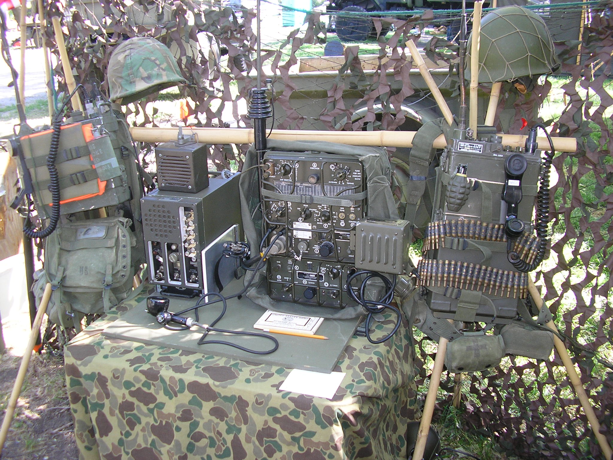
Below is my “GRC-9” set up on the Pacific beach at Spooner Cove near San Luis Obispo CA during less stressful times. (Actually, it is a GRC-87 – do you know the difference?*) We were running “Coastwatcher Ops” and transmitting Bikini Reports back to Net Control at Camp San Luis Obispo. This was during the Military Radio Collectors Group meeting in May 2010.
(*The RT-77/GRC-9 receiver-transmitter when deployed with the G-43 generator, LS-7A (or LS-203) speaker and the ME-61/GRC field strength meter is defined as the AN/GRC-87 “system”. (TM11-5820-453-10, 10MAY1963 refers) ) If you’re keeping score.

The distance from here to Camp SLO NECOS was 9.2 Miles over hilly, rocky terrain; they were running a TCS set. From here to another station in this 3-station Net was 3.3 miles, and from there to Camp SLO was 5.8 miles. That station was running another GRC-9 in a portable configuration however he was using the DY-88 Dynamotor power supply.
Under the conditions at that time (appx 1000 hours local) the signal to noise ratio of received signals was 2 to 3 times better on the whip than the AT-101 wire which surprised us. It was running approximately northwest, broadside to Camp SLO, averaging about 6 feet off the sand. CW and Voice Comms with the 15′ whip antenna were Q5.
I didn’t note the FoF2 critical freq at that time to see if the low wire would work in NVIS mode under those conditions. Apparently it was lower than our 3885 freq and/or the D Layer absorbtion was very high then. So little/no skywave contribution.
We ran the standard ground radial wire array, G-43 hand cranked generator and a battery for the receiver to save the “power supply”. The TCS was running a 30 foot inverted L and the other GRC-9 was running the standard whip antenna. This setup would have been a very workable tactical circuit. Authors Photo:


Above is a typical mountain top campsite to cover all circuits. There is the GRC-109, GRC-9, PRC-47 and the mobile GRC-9 all on-line. However, looks like the flash caught the Midwatch off guard. Zzzzzzzz. Good thing the Sergeant wasn’t around!
Below is a shot of our Perimeter Defense Force checking out the Company Command Post. Note the GRC-9 AC Power Supply built in the .50 Cal Ammo Box on the ground. Provides all voltages from 120 VAC.

Above: The GRC-9 was operational at the Military Vehicle Collectors of California April 2013 Rally at Camp Delta. A Battalion Communications Center capable of handling comms relay between any possible Time Warp from 1944 through the 1970’s. We worked lots of stations on 40 meters CW with the GRC-9 and its’ simple whip antenna. Always a hit with the visitors.

Above: Later that night…..

Don’t let this happen to you! Do your PMS and then double-check everything!

Above: QSL Card from the USS Pampanito SS-383, normally moored in San Francisco near the Golden Gate bridge. I worked their ham station, NJ6VT aboard the sub on CW with my GRC-9 from our Forward Operating Base in the Sierra Nevada mountains, see below. Her wartime Navy call sign was NJVT.

Below is a shot of the GRC-9 in the field using the .50 caliber AC power supply. “You have a strange rushing sound in your Transmit audio”….Yup…. This is the setup I used to work the USS Pampanito submarine on CW during a “Museum Ships On The Air” weekend. Better than 150 miles on 40 meters during the day.

Above is another shot while sending Ditties from FOB (Forward Operating Base) Margarita….The little AC power supply in the .50 Cal ammo can makes it convenient to work in camp. Especially when you bring the generator to run the Blender anyway!
Below: Would you believe a solar-powered GRC-9? Been there, done that. Here we are set up in the mountains west of Lake Tahoe at OP COMMANDO, monitoring kayak traffic 2000 feet below us on the North Fork of the American River. Panel charged the deep cycle battery which powered the sine wave inverter that powered the ammo box power supply which powered the GRC-9. Inefficient as hell but it worked!

Below is another shot of that same position – we also had a PRC-47 going on CW and LSB as well. There is the wreckage of a C-46 Commando somewhere within a mile of this location. Very dense forest in here. It’s on our list for a search expedition. This spot will make for a very good base camp.


Above: Mounting my other GRC-9 in the back of the old Bronco makes it pretty convenient while camping. I can check into the Saturday night West Coast Military Radio Collectors Group net on 3985 KC AM, even from my sleeping bag when it gets cold up here in the mountains. I can even get the latest soccer scores from Radio Australia while zipped up.
Many “gray hairs” later, it’s still going strong at campsites. I’ve put a lot of miles on this old set; never fails. It has all matching serial numbers, 2974.

I usually run 80/40 meter coax-fed “fan” dipoles but sometimes just a quarter wavelength wire or the MP-57/MS vehicle-mounted whip depending upon how long I plan to camp in one place. If the raccoons wake me up at 0345 I can check the propagation worldwide without getting out of my Extreme Cold Weather sleeping bag.
The Bronco is pretty cramped with camping gear so I had little room for a huge DY-88 dynamotor power supply. So I built a small transistorized power supply that runs off the vehicle 12 Volt battery; with the little supply sitting under the passenger seat. It works well and is more efficient than the dyno but I miss the Dyno Whine during Transmit !

Above: The GRC-9 at work down in the Commo Bunker sending out the nightly SITREP at Zero Dark Thirty.
(BTW, it’s an old military phrase that has been around since clocks were invented and the troops had to get up early. Then the Hollyweird crowd discovered it and was so enthralled with it they named a movie after it…. Same with “Hurt Locker” but I digress…Those people need to get out more often – yeah, right.)
UPDATE: 60 meter trials with the GRC-9 on CW:
I set up the GRC-9 on the 60 meter Channel 4 CW frequency of 5373 kc. Driving a 40 foot random wire in the trees from the Commo Bunker.

Experiments on 60 meters CW: It worked well, getting into the KPH SDR receiver about 50 miles from here, mid-day, at an S-7 or so signal strength. Keying dynamics and drift stability were both acceptable on that frequency. I used a counter to set the frequency to mid-channel as required.
More experiments, remote contacts and field ops are in order.
—————————————————————————————-
A note on the GRC-9 home brew power supplies discussed above: I have gotten many requests for the design of the various AC and DC power supplies that I have built. (These are “one-of” power supplies for my own use – I don’t manufacture or sell them.)
As we know, the GRC-9 requires a number of different voltages from the power supply. 580, 108 Reg, 6.3, 1.5 ……I was able to build supplies around junk box parts I had on hand, but the design is entirely dependent upon the kind of transformers you can get – it is central to any design you could make. It completely defines the circuit specifics you will need.
The AC transformer I used in the Ammo Box supply is from an old oscilloscope PS, that “TV” transformer is a Triad R-50BC – long obsolete. It had lots of different voltage windings. Along with a big choke it was a challenge to package everything into that small box.
The DC supply is built around a transformer from an old Heathkit mobile transceiver DC supply that was scrapped – and it also had a lot of winding voltages I could work with and adapt. Especially the all-important primary and feedback windings needed for a 12 VDC transistor power oscillator.

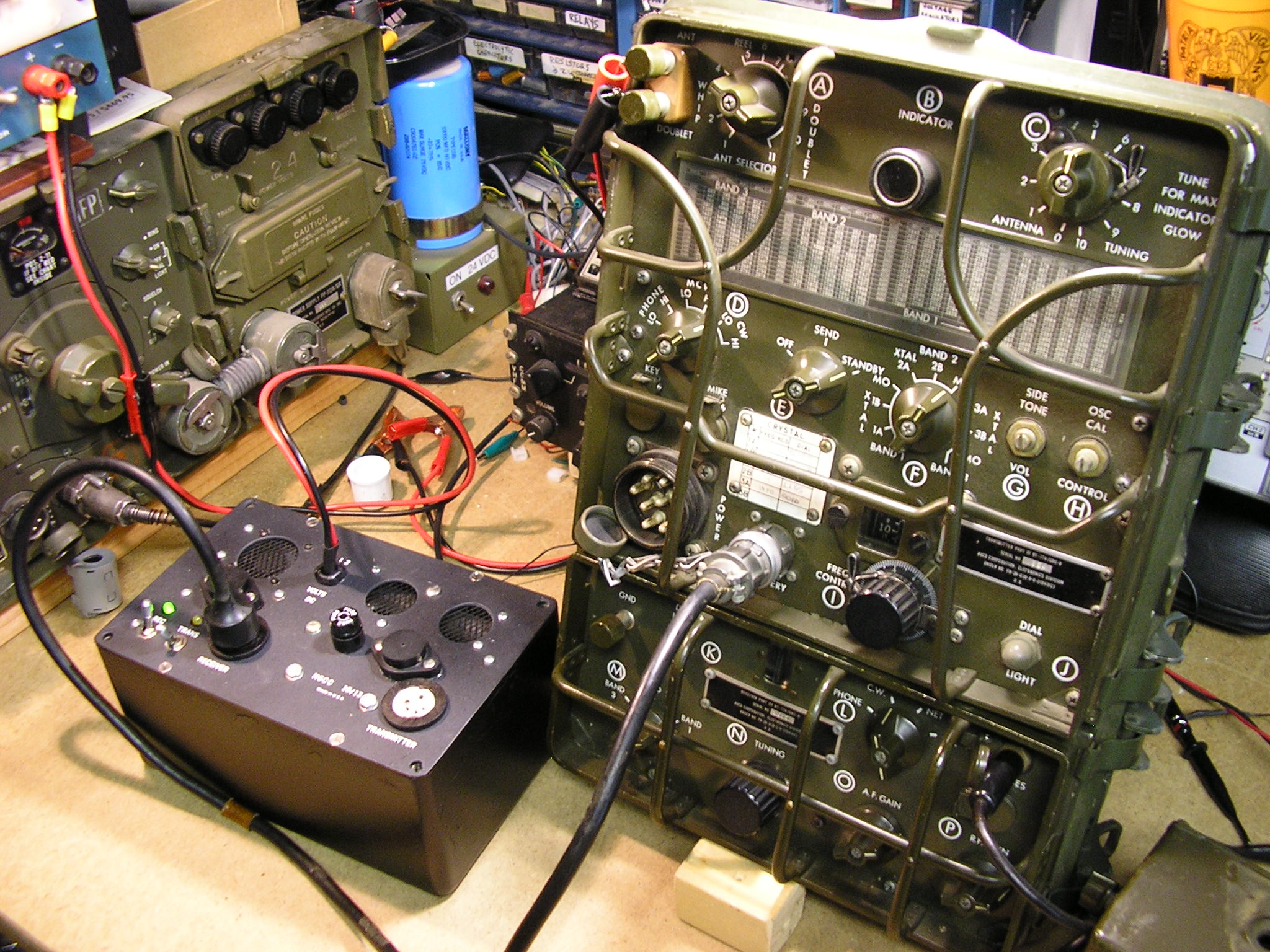
Above: The GRC-9 set up on the workbench along with the “Ammo Box” AC power Supply. A small, simple, compact solution to powering the GRC-9 from AC sources at home or in the bush via a generator.
Without either of the AC or DC oscillator transformers my design would not be useful to anyone trying to replicate them. That said, however, the designs are otherwise straight forward and follow the ideas in any of the older ARRL handbooks for providing those voltages. I used adjustable LM-350 voltage regulators for the +108 and 1.5 volt supplies.
I chose to regulate the receiver filament voltage to protect the tubes and I also regulate the receiver B+ in the supply. Consequently, the VR105 (OC3) tube in the GRC-9 does not “fire” with externally regulated +108V applied and this works well.
Unfortunately no one makes suitable (affordable) HV power supply transformers any more in the “transistor age”. Especially transformers for DC-DC HV converters. You must work with what you can find – and that took some digging….
And that was part of the fun……
Above: The GRC-109 DC-DC Power supply built into an excess GRC-109 transmitter box. This supply powers the GRC-109 transmitter and receiver from 12 VDC. Since both the GRC-109 receiver and the GRC-9 receiver can both be powered from the BA-48 battery or the later BA-317/U (the common 4 contact connector), this supply also powers the GRC-9 receiver directly as shown above.
It uses the standard CD-1119 GRC-9 Battery Cord as seen here. A future project is to include a +580 VDC GRC-9 transmitter B+ supply inside this box as well. One box will do it all. I just have to find a big DY-88/105 power supply chassis connector.
Look here for further details on that DC-DC power supply:
http://www.n6cc.com/angrc-109-special-forces-radio-set
———————————————————
Problem areas: Both of my GRC-9’s have been very reliable, they have all the original tubes and capacitors and I have not needed to make any* repairs on them despite 20+ years of frequent use, both mobile and portable. That’s after their military careers.
A “quirk” that the GRC-9 exhibits is a slight chirp when running CW transmissions in VFO mode. This is due to the design / dynamics of the oscillator running in VFO mode. Every GRC-9 that I own or have heard exhibits it. It is quite stable under crystal control however.
It is not objectionable to me or to other operators I have worked. The other guy knows you are running a classic rig, not some computer with an attached antenna. I call it “character”.
The only item needing attention is the bias battery used to keep the receiver 3Q4 pentode AF power amplifier tube properly biased. (The receiver will work without a battery installed, see below.) I remember recalling that my receivers “sounded” better with the battery installed – and hence the effort to supply that voltage – and the designers thought so as well.
UPDATE: I needed some DATA! The Sylvania tube data for the 3Q4 states that to run the tube as a Class A audio Amplifier, the grid bias needs to be – 4.5 volts and that the audio input not exceed +/- 4.5 volts AC. (It doesn’t want you to drive the grid POSITIVE – the definition of Class A.)
The data sheet states that the tube biased Class A will exhibit 7% distortion. Seems like a lot to me but in keeping the circuit simple and recognizing that its use was not intended to be “Hi Fi”, 7% was deemed to be acceptable.
So I did an experiment. I set up the receiver to hear its crystal calibrator at 2.00 Mc, driving a 600 ohm speaker. (The receiver audio impedance switch was set to 250 ohms for this test and that alone should produce some distortion by itself). This produced a beat note in the receiver while set to CW. I looked at the output with a scope, both with and without the bias battery.
Although I don’t have an audio distortion analyzer, at low audio levels I could see no difference on the scope, the sine wave was very clean in each test. I was a bit surprised. At high audio levels the stage was driven into some distortion and removing the bias made that worse-looking.
I also listened very carefully to bias – no bias condition and I don’t think I can hear any difference at “usual levels” although my hearing has taken a beating over the years. (An Audiophool would probably go apoplectic however…)

Above: Fun on the work bench.
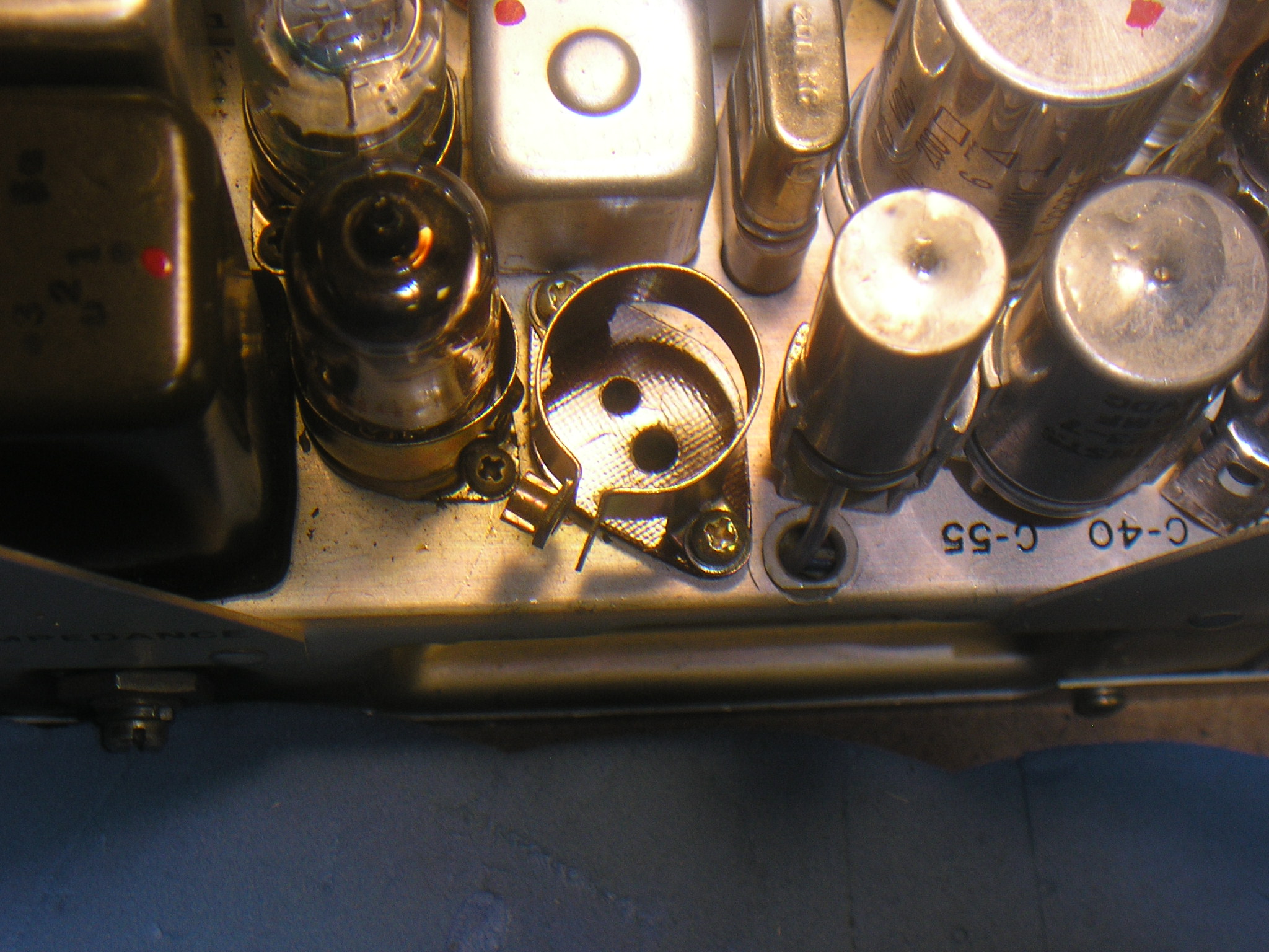
Above: The socket and clamp for the BA-1293 bias battery in an RT-77A. The RT-77 used a hard-wired battery. (The larger diameter + contact is grounded, the -4.5V goes to the smaller socket connector.)
Below: A BA-1293/U made by Duracell in April 1982 on a 1982 Contract. Labeled 4.02 Volts. As found in a GRC-9 that was refurbished by the Sacramento Army Depot. (The battery was dead in 2026)
This one contained a stack of 3 type 625 Alkaline Zinc-Manganese Dioxide button cells spot-welded in series:
I had previously built replacement bias batteries for that application; I used three 1.5 volt AAAA cells from an ordinary 9 volt Duracell battery. Left in series via the spot-welded stainless steel jumper straps, they make a good replacement battery of -4.5 volts. A bit of heat-shrink tubing or tape, and a salvaged battery connector, it fits in the original battery holder. That battery will last for years – the shelf life of the cells. Improvise, adapt, overcome.
Note that some of the newer 9 Volt batteries utilize individual rectangular cells, no workie. This one is fine..

Above: The jury-rigged bias battery as installed in the socket using a defunct BA-1293 battery base and pins (I didn’t have a complete battery with the plastic case). A bit of black electrical tape and heat-shrink tubing holds it together. Works fine but won’t pass inspection….
“If it’s stupid – but works – it isn’t stupid”
Murphy’s Laws of Combat
It may not sound any better in actual practice but the tube will draw its rated plate current and have minimal extra distortion when biased properly into linear, Class A operation. (Why would you operate any tube with a filament, plate, grid or screen voltage widely different from the design voltages and expect good performance?) It’s a big DUH!
Next I looked at the receiver B+ current draw, with and without bias to see if I could detect any change due to the bias. Removing the bias increases the B+ current draw by about 100-200 microamps from an overall 10 milliamps quiescent draw at low output levels. Negligible difference. Probably more of an increase when the volume is turned up – I didn’t test for that.
No surprises here, it’s all about Class A operation. The 3Q4 pentode specs state that it will deliver output with not more than 7% distortion when it is biased correctly for Class A operation. When the Volume is turned up sufficiently to drive the grid positive (with or without the compensating bias) you will get even more distortion. I’m going with the original engineering design – I use the battery. The designer knew what he was doing.
————————————————————————————————————————————————————————————————–
Gremlins Hideaway: One of my GRC-9 receivers had an annoying, intermittent receiver “cut-out” problem that occurred while turning the tuning knob. The receiver would just quit, sometimes preceded by a scratching noise while the knob was being turned.
I assumed it was debris between the tuning capacitor plates causing that (high impedance) stator circuit to short to the grounded rotor plates. I tried several times* to blow the plates clean with a micro duster – that seemed to help – but not permanently – sometimes the problem re-appeared at a different knob position. On the right track.
It started doing it again! I pulled the receiver and removed the shielding covers and blew it out again. Kinda worked. Upon CLOSE examination with a high-magnification eye loupe, I saw a few tiny fibers protruding off the rotor plate but they were not positioned to touch the stator. Ah Ha !! Tin Whiskers.
They were maybe 1-2 mm long, and looked to be about the diameter of spider web silk – if you can get the light just-right to even see them. Maybe a couple of microns in diameter. If they are here, they are probably elsewhere in the capacitor assembly. They are apparently strong and stiff enough to withstand the micro duster gas blast in some areas that were hard to get to.
Tin whiskers are a well known problem in the electronics business. They have greatly compromised all kinds of electronics since the environmental-cases started banning lead from tin-lead solder; and apparently even before that. This is the “RoHs” initiative started by the EU and then adopted by the US and others in a knee-jerk reaction. “A planet completely free of any and all risks.” But just a little bit of lead alloyed in significantly inhibits the formation of these tin crystal “whiskers”.
Tin-lead alloy solder does not have this problem; lead-free solder and native tin plating DOES. Some really interesting physics going on here….(If you have done any soldering with the lead-free stuff, you know it does not work very well as a solder, future whiskers notwithstanding).
My radio was made well before that decree started causing short-circuit problems, but the plates of my variable capacitor are apparently tin plated. A thorough “cleaning” with a pipe cleaner or a slice of a business card slid inside each rotor-stator plate gap knocked off any other whiskers that were causing the problem with this set.
Back in operation, no more receiver drop-outs. (By the way, the problem section of C7 was the local oscillator tuning – the LO stopped at certain rotor positions, thus killing the receiver).

Take a look at the tin whiskers on this variable capacitor frame. (Obviously not a GRC-9 capacitor – but you get the idea!) Holy crap! (Photo: NASA)
According to NASA’s website on Tin Whiskers, at least 10 satellites have been lost and up to 7 nuclear power plants have been partially shut down due to tin whiskers shorting out critical circuits. Is the “cure” worse than the problem? Look at that photo and extrapolate – you be the judge.
Well, the receiver quit many more times after I had written the above. A pipe cleaner has become an essential tool, so now one resides permanently on the grille protector as a reminder and ready remedy:
—————————————————————————————————————
These are wonderful pictures. I should try and get something like this going in the Rochester NY area. These radios are just great when deployed in the field.
Rw
Hi Tim
Great photos and great job getting some of the old stuff working.
I have a GRC-9 question for you. I have a GRC-9 and a GN-58A without legs or cranks and a G-43A complete with legs and cranks. I purchased a GRC-9 power cable from a guy in Italy that has no markings. It fits the GRC-9 fine and the G-43A fine, but it does not fit the GN-58A. The connector shell is a few thousandths to large.
I had thought the cables for both generators were the same.
Have you seen this before?
Allen
WA7GSK
Hi Allen – That’s a new one on me; I thought those parts were all backwards compatible. It is possible that your cable was made by a non-US user and they didn’t “get it right”. I know that Yugoslavia for example fielded a GRC-9 / clone?, maybe under license or maybe not. There may have been others as well. Since your cable is unmarked, that is a possibility. The stock US CD-1086 cables had a metal ID tag on them.
Just a guess…
Thanks for visiting my website and have fun with yours – they are capable and fun!
73, Tim
Why all this palaver and messing with batteries for a neg supply. THere is a chip called the ICL7660 which is esp developed for this – it will provide -10 V or whatever you want at about 20mA out – just a capacitor charging system no no transformer winding at all required all you need is some DC from inside the existing chassis to run it. My tuppence worth. Tim Fidler in WRE , NzL
Hi Tim – Yep, an interesting IC that would certainly do the job…just have to feed it with +4.5 VDC
Thanks for the idea! Tim
Hi Roy – Thanks! If you’re not having fun, you’re not doing it right!
HI !
Nice pics of a sure nice and exciting stay at the beach !
50 years ago I have been instructor for the GRC-9 and many other radios, RTTY and crypto-equipment !
Hi Jim and thanks for the note. Yes- these old contraptions are fun to play with. I hope they did the job for you when you were doing it professionally! I use mine a lot and it has been very reliable…
73, Tim
Thanks for updating, I see you received the link I sent to the special forces patrol, cool stuff. I am slowly gathering all the extras for my GRC-9, just got the counterpoise set and am awaiting the arrival of the GN-58. Now need to find a set of hand crank handles for it. Keep up the good work.
Mark
K1HF
Hi Mark – Yup – That Signal Corps movie surfaced a few years ago and someone figured how to do a “frame grab” from it. I wonder how many similar treasures from the National Archives are yet to surface! Good luck with yours, you’ll get there. I started collecting my set about 20 years ago and parts were a little more available back then. The hunt is on for the Spares box!
73 & thanks for visiting my website.
Tim
N6CC
Hi Tim,
WOW!! Fantastic pictures. I picked my GRC-9 off of EBAY part by part and put the
whole TX/RX together. What a fun Winter project. I now have the chripy little guy
on 40- and 80 meters with a home brew solid state inverter power supply that I picked up from a Italian electronics guy. Am now modifying the DY88 dynomotor power supply with a 580 volt solid state power source, and will keep the vibrator running for a while for the RX voltages like 108 v and 1.5 v filments, (SOUNDS NEAT). But next year will work on having he DY88 running all solid state power– keeping original box looking old. . How about a sked ??
And thanks for the RX bias battery tip — so that’s why the receiver is a little grungy ..
Keep Well..
Jerry WA6BXV
Also the operator at USS PAMPANITO SS383 SUBMARINE.. YA !!
Hi Jerry – Thanks for the note! I’m sure you will have a lot of fun with your GRC-9 – it’s a kick. The SS replacement circuitry inside the DY-88 may be a first! But I agree, the dyno and vibrator make for agreeable “music” while running. Yes, the TX is a bit chirpy on CW when in the VFO mode but very clean when using a crystal. I like to think of it as Character and it is not too objectionable when heard. They all seem to sound like that in VFO mode..
OK on radio Ops on the Pampanito – I have worked the boat a number of times on CW. We were even hoping the boats’ SCR-522 would become operational on 2 meters AM so I could try to contact the boat with my ARC Type 12 from Mt Diablo, a favorite local camping spot. I can see the sub from there, but just barely. I was up there this past Saturday with the GRC-9 and other gear.
Now that I have fixed the GRC-9 receiver problem I need to get it reconnected up and smoke tested – then time for a sked. I usually guard 7050 KC.
Thanks for visiting my website & 73!
Tim
Hi, Tim: I have thoroughly enjoyed your e-mails and this site. I used an AN/GRC-9 when is was in the Army back in the 1960s. I thought it was a really neat rig, and would love to have one now. However, those I see on eBay are priced WAAAAAY above my reach. Maybe I’ll get lucky and someone will leave me one from an estate. 😉
I have a DY-88, and you are so right about the lovely sounds from one. I used to play the Highland Bagpipe up until I got RA, and the DY-88’s pitch, both from the dynamotor and from the vibrator, is the “A” the bagpipe plays (actually Bflat) only about an octave apart. They harmonize so nicely.
I want to try to use my DY-88 with one of my AN/GRC-109s sometime. Take care, and vy 73,
Ken W7EKB
Hi Ken! That’s cool about the Bagpipe “resonance”..Who knew! The sound of that DY88 dyno in particular just sounds like “precision” to me. I really appreciate well-designed and built equipment of any type….
Yep, GRC-9’s are getting expensive these days – long gone are the $54 RT’s from Fair Radio back then. They must have had a big pile of them…I found a second one at a swap, NOS for $50 with manual and grabbed it probably 20 years ago, glad I did. One is in the truck, the other is my field Ops set….A DY-88 powering a GRC-109 would work but the TX B+ may be a bit high for the components in the GRC-109 transmitter. I know you’re careful..
Have fun with this gear and keep it on the air!
73, Tim
The FAIR RADIO early prices were the nadir of GRC-9 prices. Before that, they mostly came out of MARS program booty, and cost up to around $150. I really think FAIR priced them too low,
at $50 each, at first. They probably had too many of them. Anyway, they were undervalued. And oh, i just remembered, same story with their GRC-109 radios.
Hi – That is mostly true about the “low” prices back then. But back then few people were interested in old military equipment, especially hams who were all about SSB Riceboxes. AM was long dead, FM was king. So Fair probably priced them profitably for the times – you could not give some of this equipment away back then. So Fair moved them out as any business should – and not sitting on them as an appreciating investment. I bought a pristine GRC-9 with an original manual for $50 back at the huge Livermore CA ham swap in 1986. I got there late in the day as they are closing down and most people had left – but there it was, sitting on the ground bypassed by everyone as a worthless lump. I recently talked to Phil at Fair Radio about the GRC-109’s they were selling in 1985. He said they got “hundreds” of sets from Army surplus stocks and they sold complete sets with both power supplies for $109. But back then you had to know CW to get a license so there was some demand for them – and probably not as a novelty military set. I bought one and haven’t stopped playing with it. The Good Old Daze!
Tim,
Will you be issuing the infamous FRAG order for Camp Delta?
Cheers!
Craig
N6CAV
P.S. I picked up a GRC-109 at the local flea market…I am working on improving my 5WPM (all that was required when I got my ticket).
Sure – Didn’t know anyone read those! LOL
Great site I just found, I learned on the grc9 during my service in the french foreign legion ’79….been a long time ago. I enjoyed it, yet was heavy as additional to my gear.
Hi Stefan – Interesting that you were still using them in 1979. Why not, if they do the job! Morse code is Morse code!
Thanks for stopping by,
Tim
Hola soy Rafael y soy radioaficionado y el indicativo es EA7EG y e visto vuestra pajina y me a gustado bastante pues yo tengo una AN/GRC9 y una PRC/6 amen de varios receptores de valvulas como Hallicrafters y otras marcas pues me gusta coleccionar receptores antiguos. tambien salgo al campo donde hago mis practicas con la GRC9 en AM aunque esta modalidad ya no se usa. Nada mas un saludo y animo con las practicas de radio en AM en el campo. Rafael-EA7EG
——————————————————————————————————–
Translate: Hello I am Rafael and I am amateur and call sign is EA7EG I seen your page and I really liked it because I have an AN / GRC9 and PRC / 6 and several receptors valves as Hallicrafters and other brands because I like collecting old receivers. I also go to the field where I do my practice with GRC9 AM although this method is no longer used. Nothing but a greeting and encourage the practice of AM radio in the field. Rafael-EA7EG
Hola Rafael – Estoy de acuerdo – la recogida de estos viejos radios si un pasatiempo muy interesante, pero en realidad el uso en el campo ya que estaban destinados es instructivo y divertido. ¿Qué pueden hacer todavía? Una gran cantidad!
Gracias por visitarnos y mejor 73, Tim
Hi Rafael and other readers
I have had GRC-9 and associated equipment for the last 20 years and have great fun with it, In my shack i have a French Version c1960, was mint unissued when i purchased it in the Netherlands, I use it with an LV-80 amplifier and can acheive 90 plus watts on the key, and with the assistance of a half wave dipole on 80 get great reports nationwide and across Europe
Perhaps we can try a sked or two, I am interested in the activity on 3985 Kcs, can anyone tell me times etc
Stuart
G0TBI
VMARS PRO and former Chairman, and one of three founders, sadly two no longer with us
Hi Stuart – We have an AM net on 3985 kc on Saturdays at 2300Z, might be tough to get across The Pond. You might try our east coast friends who run a net on 3885 kc, also on Saturdays at 1300Z. You could probably hit them with the power levels you have… some more details here: http://www.mrca.ar88.net/Nets/default.html
Times vary a bit seasonally.
Thanks for visiting my website & happy 2020!
Tim
THE BEST SITE ABOUT GRC-9 !!
Hi Lampros – Thanks! It has been a fun project with a fun radio…Hope you can get some useful information from it…
Thanks for visiting my website….
73, Tim
Hey Tim,
Got a Lewt RT-77 and I need the J102 connector. You happen to have one to sell or know where I can get one. Also, do you know the J102 wire color coding? I have the schematic, but in 2 instances, I have found several wires in the schematic located in different pins and don’t know which is correct. Sure would like to get it operational, but I sure don’t want to burn it up sending 500 volts the wrong way!
Thanks,
Art
Hi Art – Sounds like someone put a different connector on the panel for some reason? I don’t have any connectors but you might keep an eye on EBay of course. That one might be pretty hard to find unless someone is scrapping a GRC-9 – which would be unlikely! As to wiring, I have the manual (TM11-263) but it does not call out wiring colors, just pin numbers and destinations per your schematic. Looks like you might have to spend some time with a VOM and trace them out, pin to associated circuit. All I can say is Good Luck! The answer is in there…
Tim
Hi Tim. Just saw this comment you made in your PRC-74 notes: “This was even more insidious than the infamous backwards-installed band switch knob on some GRC-9s.” Can you elaborate? Have not heard about that before. Thanks for the great writeups. Bill
Hi Bill – That was “one for the books” HaHa. I had worked on a friends GRC-9 and it was completely screwed up. Upon examination, the transmitter bandswitch made no sense. The wrong circuits were switched in as indicated by the panel switch position, nothing worked frequency wise. Upon further examination, the transmitter bandswitch wafers were all in the wrong positions and this radio could have never worked – it would require removal of the entire bandswitch, disassembling it mechanically and electrically and reinstall – WAY beyond anything reasonable. The radio could have NEVER worked. How was this possible?
Then I realized the radio was fine – the band switch KNOB had been installed backwards – it pointed 180 degrees away from where the switch actually was! The switch internals were fine. But the knob and shaft have a 180 degree ambiguity in its rotational position. I just removed the knob, rotated it 180 degrees, put it back on the shaft – presto, normal operation. That was a real hair puller.
You’d think the design would preclude that possibility by having only one “flat” machined on the switch shaft – or knob, but they each have TWO. Sheesh!
I thought that would be a unique problem until a buddy described another GRC-9 that he had that was haunted…couldn’t possibly work….couldn’t fix it …Same problem – he was amazed at the simple “error” involved….
This is a good example of “Occams Razor” which states that the simplest explanation is usually the correct one [sic]. Indeed
Very nice Pictures, I love this old Rubbish, in the Time I was in the Navy we got this Equipment on the Emergency Bridge!
Thank You for this Page!
vy 73 dh4bae, Chris
Hi Chris – I didn’t know that these sets had been used aboard ship. But I guess, Why not? At least as an emergency set…
Thanks for stopping by.
Auf Wiedersehen & 73, Tim
It’s been a while, but I had one or two GRC-9s that were identified to a Navy ship, if I recall, a destroyer class vessel.
Hi Hue – The GRC-9 was carried aboard many Navy ships in the 1950-60’s for “landing party” operations. The Radioman 3 & 2 Rate Training Manuals (NAVPERS 10228-D, 1964, as an example) in the 1960’s described the GRC-9 and its use. The SCR-536 (BC-611) was also carried aboard in earlier days. I wonder if your sets were painted Haze Gray. I’ve never seen one like that but “never say never” HiHi…
Thanks for checking in…Tim
Foreign militares have updated and upgraded the AN/GRC-9.
The French produced an amplifier based on the output tube, times 3.
The Germans took the receiver and gave it a fully solid state power supply.
Hi Rudolf. Yes, those modifications were very well done and the amplifier was a great idea, well engineered. Those kinds of changes really extended the useful service of the GRC-9. I think the Germans also repackaged the receiver into a stand-alone unit that was independent of the transmitter. That would be very handy…All good ideas.
Thanks for stopping by! 73, Tim
Hi, fantastic radio and great WEB site.
I have a working GRC-9 here in the UK along with the DY-88.
The set is 99% complete as a ground station with the G-43 generator and as a vehicle setup with the DY-88, however the last 1% is a big problem for me because my GRC-9 is missing the TX and RX name plates as well as the long frequency chart that clips on to the front panel of the TX.
The GRC-9 was not as popular a set in the UK as it clearly is in the USA.
Is there anyone who could assist me in obtaining American versions of the TX and RX name plates as well as the frequency chart?
I have tried in the UK and Europe and over the last 6 years I’ve been looking for these parts, I’ve not been able to find them.
TIA,
Keith G4MSF
Hi Keith – Thanks for the note. I sent you a PM with a photo of my tuning chart, it may be useful to use as a representative tuning chart for yours. Hard to photo due to the shiny surface. And my cheap camera!
Sorry, but no data plates available here, maybe someone else has some available?
These sets are pretty popular and it seems that a lot of them were made, and survived. As you probably know there are many fans in the Netherlands and also Argentina. They are fun to use – have fun with yours! 73, Tim
What are the crystals for the transmitter which mhz are they
also this is a top website (sorry for my bad English i m from holland/netherlans)
with kind regards Stijn
Hi Stijn – The GRC-9 incorporates a doubler stage in the transmitter. So the crystals must be one-half of the operating frequency out the antenna.
I use the old FT-243 crystals and they work fine. I have a 5055 kc crystal in one of my positions so the transmitter output is on 10,110 kc.
Makes sense?
Your English is great!
Thanks for stopping by my website
Hallo Stijn – De GRC-9 heeft een verdubbelingstrap in de zender. Dus de kristallen moeten de helft van de werkfrequentie buiten de antenne zijn.
Ik gebruik de oude FT-243-kristallen en ze werken prima. Ik heb een 5055 kc-kristal in een van mijn posities, dus de transmitteruitgang staat op 10.110 kc.
Klinkt logisch?
Jouw Engels is geweldig!
Bedankt voor het langskomen op mijn website
73, Tim
Hello all,
I am surprised this AN/GRC-9 is even still around. We used it mainly for CW transmission. but that was 55 years ago and what I remember was it was bulky heavy and usually took 3 people to carry it.
Enjoy
MarkGray.
Hi Mark – Yes, sounds about right! Technology certainly moved on, but in its day it was pretty “high tech” I think. There are apparently a lot of them still around and they work fine. And still heavy…
Thanks for checking in,,Tim
Hi Tim,
Thanks for the interesting text, pictures and measurements on distortion regarding the bias battery. My 50cents on the topic: I would always replace the bias battery, mostly not for audio quality, but to maintain a reasonable current in the audio amp tube. Without a negative bias, it will draw too much current, and tube-life is shortened.
I so far replaced two batteries by disassembling the original ones, and putting a 6V lithium photo battery (I believe they were PX28) inside. This solution should have a long shelf life, and since the new battery fits in the old shell, looks original. The higher negative bias will produce a little less plate current, and might lead to distortions if the volume is cranked all the way to the max, but this is not a concern to me, as long as tube-life is prolonged and the original look is maintained.
Hi Gregor – Thanks for the note. Installing those small batteries inside the plastic plug-in is a good idea, looks original as you said. An extra 1.5 volts of negative bias probably generates an imperceptible amount of distortion versus -4.5 volts. It’s actually hard to measure without a dedicated distortion meter. But the original design is “good enough” for communications-quality fidelity..
Thanks for visiting my website !
73, Tim
Hello.
By creating a draft on this radio on the French wikipedia, I came across your article that I used in reference. I allow myself to have found a photo of a radio made in Italy by Elmer S.p.a which was used by the French Army:
https://www.doctsf.com/grandlivre/fiche.php?ref=16863
Concerning the French production, the first contract was in 1953 for 3000 devices by T.R.T. (Télécommunications radioélectriques et téléphoniques).
Good continuation.
Excellent photos and story! My GRC-9 works fine except for low drive to the control grid of the final and suppressor grid as measured via the octal socket. The voltages are about half of what is specified. This messes up modulation as well. Otherwise DC voltages are as per manual, including those on the pins of the tubes. I have replaced all tubes. The drive is similar on all three bands. I wonder if you or others have come across this fault and managed to rectify. Thank you.
Hi Bronek – That’s a problem I have not seen (yet). Are you saying the Screen and Suppressor voltages on the Octal test socket are about one-half rated but the voltages on the actual tube socket pins are OK?
You might start by looking for leaky capacitors, C-114 for the PA Grid and C-117 for the PA Suppressor problem. C-142 for the Doubler stage for low grid drive. If they are leaky that could pull down the associated voltages.
Please let us know what you may discover!
Tim
From 1952 to 1953 I was with 2nd Batt. 5th Marines, 1st Mar Div TACP..
We used the angry-9 every day to check in with net control..Devastate Baker. OH! Budweiser14 was our 2nd Batt 5th Marines TACP call sign.
We requested Air strikes with bombs..napalm..20mm. Our team was 2 USMC or USN fighter pilots and about 6 to 8 mos 2531 field radio operators. That radio really worked. Our last big hit against us was..Reno..Vegas and Carson..and I had to relay air strike request from the forward outpost. BOY did that hand generator tire me out.
Sgt Jim USMC Vet
Hi Jim – Thanks for checking in (here!).. Good info there, your memory is pretty good!
Nothing like Ground Truth from someone who was actually there, doing the job…
Thank you for your service Marine…. S/F
Tim
Thank you for building and publishing a GREAT web site! I have (somewhere) a PS for the GRC-9 that was salvaged from an Army surplus store that burned down some time in the 80’s and have always been interested in the radio. My only “Green” radio at present is a PRC-77, but I am hoping to grow my collection.
Thanks again
Ken
Hi Ken – Thanks for the note…Yep, get started on gathering the parts for a GRC-9 setup, it’s a rewarding pursuit and a useful, cool radio…!
Thanks for the visit & hope it can help you get more into Green Radios!
73, Tim
Hi Tim, I’m stefano IU1MGO, I used grc 9 during my military service.
I have one with very low bias voltages, I can’t find the c114.
can you help me?
Meanwhile, thanks for the beautiful photographs.
73
Hi Stefano – Apparently C-114 failure is a known problem with GRC-9’s (I’ve not seen it with my sets). However a guy developed a good “work around” to fix it since the part is pretty inaccessible. He is sending me the information (paper copy) – I will scan it and post it here when I get it…Hopefully it will fix your problem. Thanks for visiting my website and stay tuned…
Tim
Why all this palaver and messing with batteries for a neg supply. THere is a chip calle the 7660 which is essp developed for this – it will provide -10 V or whatever you want at about 20mA out – just a capacitor charging system no no transformer winding at all required all you need is some DC from inside the existing chassis to run it. My tuppence worth. Tim Fidler in WRE , NzL
Hi Tim, great to see the radio set in field dress! I live in the UK, and there are a lot of ‘1940’s weekends’ around here. And there are always a few Jeeps about with. you guessed it, a ‘9’ riding on the back. Most are for show, but a few are kept going by their owner. One guy was on his chatting away until his crank operator got tired, great fun. You keep up the good work, I’m going to start looking for mine, even if I have to hide a smaller radio inside the case, hi hi. 73;s G7FTD/WB7WCB
Hi Ken – Great to hear about the “living history” efforts across the pond. A great way to learn and demonstrate history!
Have fun and thanks for checking in….73, Tim
Good afternoon. Came across your site with a quick google search. I have a couple of restored and functional BC-659 Radios (SCR-620) and I have recently started to source all of the components of the GRC-9. I have the complete GN-58 and DY-88, as well as the Receiver/Transmitter. I am having problems sourcing the power cables for the power supplies. I have a couple of questions.
1. Do you happen to have an extra CX-2031A/U for sale or know where I could find one?
2. Are you still making the power supplies in the .50cal ammo can as seen in your photos? If so, I would like to buy one from you.
Looking forward to hearing from you soon.
Dave
Hi Dave – Looks like you’re on your way to a Korean War setup!
As you have found, those cables seem to be hard to find, I don’t have a spare but they (or connectors) might show up on EBay on occasion. Maybe Colombia Electronics EB store – he had some GRC-9 parts for awhile.
As to the ammo box PS it was a “one of” I built for my set with some parts I had available, I don’t make them for sale. But not too hard to replicate with some scrouging for suitable transformers etc…
Good luck – fun, interesting radios!
Thanks for visiting…Tim