
UPDATED 12/22/2025:
My favorite “Black Radio”. The AN/GRC-109 Special Forces Radio Set, AKA the “GRC-109” and “ANGRY 109”. Probably the ultimate “SHTF Radio” for trained (or trainable) personnel. The GRC-109 and its “father” the RS-1 include a “mystique factor” second to none.
The GRC-109 was “The Jeep of the radio world” as dubbed by a former Special Forces radio operator in Vietnam (Reference 53).
Background: The RS-1 and GRC-109 are both in direct lineage from the SSTR-1 set used by the Office of Strategic Services (OSS) operatives in WWII. The SSTR-1 was designed to be operable almost anywhere with a wide variety of power sources. A principal packaging requirement was that each of the main components could be “concealed inside a loaf of bread”. Think about that. There is an interesting 1943 OSS instructional video on YouTube demonstrating that concealment method as well as the operator training.
The SSTR-1 set below. It could also be installed or carried in a small suitcase.

It’s easy to see how the CIA’s RS-1, RS-6 and the later GRC-109 followed the separate TX, RX and multi-voltage, AC-DC power supply partitioning. Photo courtesy of Andy.
As with the SSTR-1, the RS-1 and GRC-109 sets both used crystal controlled transmitters with sockets for various crystal types. Their power supplies both included voltmeters for setup. They each have a built-in key and superhet receivers. None may easily fit inside a loaf of bread but they are dividable to simplify carrying and concealment, a critically important detail. The RS-1 and GRC-109 could be concealed in a swamp.
With a transmitter output of 8-15 watts over a range of 3 to 14 mc the SSTR-1 could do the job well. The GRC-109 had similar power output over a wider 3 to 22 mc range. Both sets could provide reliable long range HF comms from the field back to “base”.
Equally simple to set up and operate, the GRC-109 can be used anywhere worldwide with many versatile power source options. Environmentally tough, they can be stored, transported or operated in almost any weather conditions. Arguably the most “bomb proof” radio set ever in the US military inventory, even (especially) by today’s standards.

A Deep Dive, probably more than you ever wanted to know. Some research, a little Myth Busting, observations and adventures below. A Work in Progress:
The “COOL METER” is Pegged on this one… With technology and design roots in the late 1940’s, the GRC-109’s were used extensively from the early 1960’s through the 1970’s and beyond by US Army Special Forces, other US military, allied units and the CIA, worldwide. (The GRC-109A was manufactured up to 1973.) The GRC-109 is a nearly identical, further development of the CIA’s RS-1 which entered service around 1950. The later GRC-109 is functionally equivalent and delivers the same performance.
Below is the CIA’s earlier RT-3, the transmitter of the RS-1 system. That post-WWII system was developed in the late 1940’s with a principal requirement for ruggedness in addition to the usual RF performance. Almost identical to the GRC-109 transmitter (T784/GRC-109 as described below) but note the absence of the connector for the GRA-71 Code Burst Keyer and a different arrangement of the external CW key and receive antenna connector posts. No other “US” markings – I bet that fooled ’em !
The GRC-109’s were also used by US Army Long Range Reconnaissance Patrol (LRRP) units in Europe as well as in service aboard US Navy PTF boats in Vietnam; it reportedly did the job well.
Below: The AN/GRC-109 at work in its element: A US Army Special Forces SSGT working with a Bolivian soldier cranking the GN-58 hand generator in the South American jungle, 1967. Maybe (?) transmitting the news that the Bolivian Army had finally eliminated Che Guevara and Castro’s exported “revolution” from Bolivia. Official US Army Photo. (Reference 105)..Got Comms? Yes.

Note the transmission line split into 2 conductors to the transmitter GND and ANT terminals. Probably feeding a dipole with WD-1/TT twisted field telephone wire as an expedient antenna. Note the receiver battery and the use of the built-in CW key.
The use of the built-in key in this image indicates he was not using the AN/GRA-71 Burst transmission keyer. This mission likely did not need the transmission security against enemy direction finding efforts. However, I would bet that the massive Russian SIGINT intercept station in Lourdes, Cuba was trying their best. Slow, hand-sent CW with offline encryption was probably adequate in this instance. More on that later.
Extremely rugged and designed to survive parachute drops and ground pounders; they were built and tested to withstand lengthy burial in the ground or even under 16 feet of water (“with or without top cover”) as part of a clandestine equipment cache. These sets have a Cool Factor 36.6 db higher than any plastic RiceBox ever made by KenYaeIc. They were, and are extremely reliable, rugged and even quite EMP-resistant.
When field repair by Swaptronix isn’t an option……………….Ditty Dum Dum Ditty
The combined Operators, Org, DS and GS Maintenance Manual is TM11-5820-474-14. It is available on the Interwebs. TM11-5820-474-24P is cited to also include Special Tools but I have not yet found a copy.
The AN/GRC-109 (AKA the GRC-109) described below is my “Daily (OK weekly) Driver”.

So there I was……..
The iconic drawing from the manual. Just makes you want to be there.
Listen in ! Click the “arrow” button…
AR
Morse code “cut numbers” crypto transmission Net callup from the Peoples Socialist Utopian Paradise of Cuba, 5800 kc, late one night. Reportedly Castro’s government (Dirección de Inteligencia) spy communications system continuing at work; the station dubbed MØ8.
Any message transmitted to or from a US team equipped with a GRC-109 would sound similar: 5 letter cypher groups as encrypted by the DIANA One Time Pad system.
The RS-1 / GRC-109 Nexus: In John Bergen’s excellent book (Ref. 3) he states: “Since the Army lacked a lightweight patrol radio that could transmit over long distances, the chief signal officer arranged for the Agency’s RS-1 to be adopted for military use and renamed the GRC-109.”
Since Generals generally speak generally, that’s what he conceptually wanted, but the devil is in the details.
Why didn’t he pick the CIA’s contemporary RS-6 set to become the basis for the new GRC-109? Same basic capabilities as the RS-1, but to also include a code burst capability. It is a substantially lighter, comparatively fragile set but it has NO environmental protection. The RS-6 was intended to be used by the CIA at safe-houses, “black bases”, hide sites etc, NOT Recon or patrolling in the boonies. The RS-6 would be more at home in a briefcase than in a ruck sack. See https://www.n6cc.com/the-rs-6-radio-set/

They could have also picked the AN/TRC-77 that had similar capabilities and was already GRA-71 compatible. The Army had successfully fielded them in Europe at the same time. It was a “lightweight patrol radio that could transmit over long distances” and already did the job, save for the extreme environmental protection needed for direct caching. See https://www.n6cc.com/trc-77-hf-cw-transceiver/
The “Angry 109” Lineage: Consequently, the US Army did not just adopt the Central Intelligence Agency’s existing RS-1 sets by simply “renaming” them as the AN/GRC-109. Despite the General’s intent. Worth exploring but to beat that dead horse:
The RS-1 had ceased production about 8 years earlier in 1955. So there were no “new” production sets in the pipeline to be “renamed” and then put in Army service as the General had suggested. Nor did the Army modify existing RS-1 sets by simply “adding” the code-burst connector to the transmitter front panel and then calling them GRC-109’s.
This widely quoted, bad “renaming” extrapolation and what it infers is otherwise easy to make based solely on visual appearances or Bergen’s paraphrasing of the Generals intent. There’s a lot more to it than a “renaming”.
The AN/GRC-109 appeared about 12 years after the RS-1 sets first entered service. They were built for different end-users running different missions, ordered under different contracts, funded by different agencies and made by different manufacturers.
The ‘109 was manufactured as a “new start” radio from the ground up but its father’s DNA is obvious. The new production AN/GRC-109 is the Army’s specified replacement, in Army service, for the capabilities the CIA’s earlier RS-1 radio had delivered.
(For its part the CIA planned to replace the RS-1 with the partially-solid state AS-3 HFCW set and others in the late 1950’s further diverging from the emergence of the GRC-109. The AS-3 had a code burst capability. Not many were built as this type of equipment was evolving rapidly with the availability of viable transistors etc.)
“The GRC-109 is just a relabeled RS-1.” “GRC-109’s are just modified RS-1’s.” Myths BUSTED. The Devil is in the details. See ADDENDUM below.
WAR. In a 27 June 1950 internal CIA memo, the Communication Division Chief was directed to make 1205 RS-1 sets available at 9 different locations for issue to agents (along with 1225 RS-6 sets among others). Reference 73.
North Korean Communists had invaded South Korea 2 days earlier on 25 June 1950.
The RS-1 had also seen later use by the CIA and sets were “borrowed” by the US military in the 1950’s and 1960’s. Especially as the North Vietnamese Communists increased their subversion in Laos and Cambodia.
Plus their direct attacks on South Vietnam while the Russian Communists increased their subversion in Berlin, eastern Europe and elsewhere. Mao’s Communists were attacking Chinese Nationalists. Castro’s Communists were lining their victims up against the wall in Cuba while also trying to subvert southern African and South American states. Some “Cold War” eh? RS-1’s and RS-6’s were delivering clandestine Intel on all of this.
Enter the AN/GRC-109 as a NEW radio set: By the late 1950’s the US Army still needed their own dedicated, small HF radio set. Their versatile GRC-9’s were big, heavy, fragile and overly complex for portable ops but also well into obsolescence for that application. The limitations of the GRC-9 was probably what the signal corps Chief was thinking about. The capabilities of the CIA’s late-1940’s vintage RS-1 looked good and the Army already had experience with those. Not the time to reinvent the wheel!
Specification MIL-R-55242 was issued, dated 21 October 1963 (there may have been earlier versions which drove initial contract work; the first sets appearing in 1961). It contained detailed, comprehensive design and performance capability requirements for what was to become the AN/GRC-109.
A similar but significantly simpler CIA performance specification for a “Waterproof Agent Radio Transmitter RT-3” was noted as “Project No. 1110” dated 2 June 1949, “from original 8 October 1948”. Reference 114.
By 1965 the CIA noted that available stocks of their RS-1 sets were “diminishing”, having ceased in production 10 years earlier. The U.S. Army was ready. (Incidentally, the CIA did subsequently use some of the Army’s GRC-109 sets. I also have no doubt that RS-1’s and GRC-109’s were available for State Department use in many US Embassies world wide as a backup communications system.)
The U.S. Army specification did reflect required performance and the resulting detailed design of the RS-1 as the functional basis for the new AN/GRC-109. However it must be supportable into the future with standardized training, repair parts and depot maintenance within the U.S. Army supply and logistics system. A cost effective solution enabled by experience. As a practical matter in the mid-1960’s they were probably considered interchangeable (except for the burst keying capability) when available and as needed.
The RS-1 sets were initially made by RDR and later, NEMS. The main GRC-109 contract was awarded to Admiral Corporation, then to Oklahoma Aeronautics for the GRC-109A. See Peter McCollum’s excellent article on the detailed history of the RS-1 manufacturing “The RS-1 HF Transceiver” found on www.spyradios.com
Aside from component designators, identification labels and minor mechanical differences the RS-1 and AN/GRC-109 are essentially the same in operation and appearance, especially the receivers, both power supplies and all external accessories. The RS-1 and GRC-109 sets were all made by those same 4 manufacturers.
As a near-clone of the RS-1’s design it is even possible they were all fabricated with the same tooling – as supplied to all four manufacturers as “GFE”, Government Furnished Equipment.
The main difference between the RS-1 and GRC-109 sets is the T784/GRC-109 transmitter versus the CIA’s RT-3. It’s where the RS1 and GRC-109 parted company.
The role of Code Burst: High frequency radio direction finding (HFDF) was well understood and employed during WWII. Many dozens of German U Boats were located and then sunk as a direct result of HFDF operations. The US Army was able to to specify a CW code-burst requirement for the new GRC-109 as a counter measure since Russian Radio-Electronic Combat (Радиоэлектронная борьба) (REC) HFDF capability was improving.
(Incidentally the Russians also fielded HF radio code burst systems in the mid 1950’s. Their R-350 Orel – Орел is an example.)
In US Army service the GRA-71 300 WPM burst keyer allowed you to send your SITREP with a lower probability of detection (known as transmission security). So a typical 25 group (word) count message would take about 5 seconds to transmit before a mobile team QRT’d, dropped the antenna and boogied. .
Enemy DF net systems and processes (their OODA Loop) at the time would be hard pressed to initially detect, analyze, decide, then queue the DF stations. Then have the remote DF stations retune and have them obtain a good LOP, all this within 5 seconds. Then report back to establish a useful DF fix. (A different story with today’s automated HFDF systems – but that’s another topic.)
Especially on long range, mobile recon teams sending these very short, occasional information bursts. To further complicate enemy DF operations the mission CEOI would have them change frequencies and comm window timing of transmissions back to base.
The transmission security function of code burst was generally not a prime consideration for Special Forces camps in Vietnam for counter-direction finding. The VC/NVA and their ChiCom and Russian bankrollers and cheerleaders already knew where the Special Forces camps were located. I don’t think the VC/NVA had a useful tactical HFDF capability fielded in Vietnam anyway. (They DID have a useful communications intelligence intercept capability at times however. (Ref. 31))
Code burst DID afford some COMINT security from low-level intercept even if some messages had to be sent unencrypted for transmission at times. It also allowed up to 28 deployed teams to use the same comm network to deliver their SITREPs quickly without needlessly tying up the channel with manual-morse.
GRC-109 Deployment:
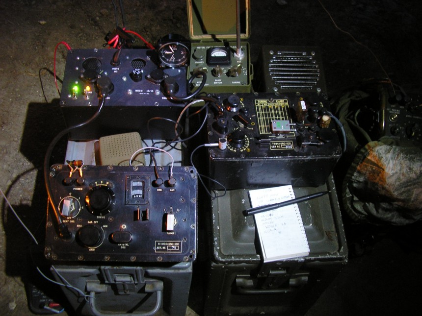
Below is a June 1968 photo taken at the Ft. Bragg NC Special Forces Training Group commo base station. The GRC-109 components with 2 transmitters and PP-2685 AC power supply are mounted in the “console”, another power supply and the R-1004 receiver on the shelf; that may be a well-traveled crystal box as well.
Along with the powered-On R-390 (non-A model) receiver tuned to what looks like 10.851 mc. The 2 transmitters band switches are set to positions 2 (6-9 mc) and position 3 (10-16 mc) ranges. Unless he is working with a training group on-base, 10 mc during the daytime indicates he is listening to someone at pretty long range; 1000 km easy!
Note the H-233 headset and LS-166 speaker: Improvise, adapt, overcome.
Photo credit: Courtesy anonymous former Special Forces 05B4S soldier.

Some interesting details above. On the desk is a J-45 Knee Key, a straight key, a civilian field strength meter – handy for tuning the T-748 transmitter into a wire antenna. That’s the 4 wire “antenna array” out the window. One for each transmitter, one for each receiver? Also note the can of C-Rat crackers and the peanut butter/cheese tin; life “on watch”.
Also note the Topo map on the wall, the telephone OPSEC warning poster and who/what is “Gabriel”? (Update: see note on “Gabriel” in the Comments section below. The James Gabriel Jr. Special Forces training area is on Smoke Bomb Hill at Ft. Bragg.)
Also note the blowtorch-charred wood of the diesel-fuel stained console – standard military decorating motif in those days. You remember.
Our photo contributor sent the following:
“We jumped in during field training exercises carrying the AN/GRC-109 along with the G-43 hand cranked generator, HS-15A headphones, batteries and materials for field-expedient antennas, weapons, food, water and more. I recall using inverted L, dipole and slopers as well as random wire. We’d sometimes urinate in a hole and drive in a metal spike for a ground.
The only time I saw the radio in Vietnam was during visits to special forces camps while preparing for or returning from a [LRRP] recon operation. My recon teams carried PRC-25s.”
More GRC-109 at Ft Bragg. Sending a SITREP from GWOA Pineland. Another staged photo: (note polished boots, pressed utilities, fill-in flash photography). Looks like the “power supply” was regretting going out and drinking all night prior…

One story I have heard is that the team XO’s were frequently “tasked” to crank the generator. It taught them (pain is the best teacher) to keep their messages SHORT!
Below: Another place and time, Ready for Inspection.
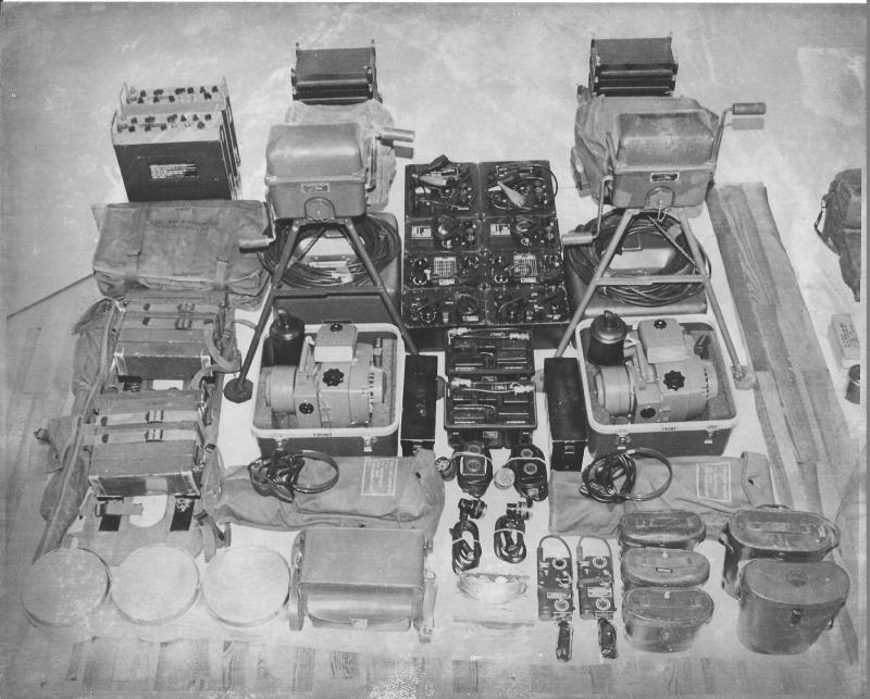
Above: A mid 1970’s photo of the US Army 10th Special Forces Group (Europe) team radio equipment laid out for inspection. In addition to the two complete GRC-109 sets, note the GRA-71 Code Burst keyers, the PRC-74 transceivers, PRC-77’s, PRC-90’s and the Homelite XLA115/1/400/1P gas powered, 400 cps AC Gensets for the GRC-109’s.
Accessory gear included the G-43 hand cranked generators, AC/DC power supplies, antenna bobbins, spare parts kits, camera kit, 7×35 and 10×50 binoculars. By the time of this photo, the PRC-74 was taking over the comm tasking formerly met with the GRC-109’s but the 109’s were still in active inventory.
Below is another Special Forces GRC-109 system on display. This type of equipment “display board” was used at Ft Bragg in the 1960’s. Official U.S. Army photo; location and date unknown.
Note the UGP-12 gas generator and the newer G-43 hand crank generator. Present is an odd LS-454 speaker; note the absence of the AN/GRA-71 Burst keyer (which may be in the padlocked box in the rear.)

Southeast Asia: It is clear that early in the Vietnam war the GRC-109 was a primary long-range communications workhorse of MACV-SOG operations (Military Assistance Command Vietnam – Studies and Observations Group). Prior to the stand-up of MACV-SOG in 1964, the CIA (and the US Army) would have used the earlier RS-1 sets in previous comm circuits in Southeast Asia in the late 50’s and early 60’s. The RS-1 was used extensively by the CIA counter insurgency work in Laos in the 1950’s.
It can also be surmised that MACV-SOG units inherited some RS-1 sets from their predecessors and continued to use them for those missions post-1964 in Southeast Asia, when or where they were available. The historical record does not always differentiate between the sets in field use. From a “report writers” perspective, they may have been considered to be equivalent.
The CIA’s RS-1 set was almost certainly in use by the US Army and others in that earlier time frame before communications doctrine changed to require the usage of “burst” and the GRA-71 high speed burst keyer and the AN/GSH-17 Receiver-Recorder system became available.
The AN/GSH-17 Recorder Reproducer Group was based upon a tape recorder that recorded the 300 WPM high speed burst transmission as received by the associated receiver(s). The recording was then processed to produce an audible 15 WPM (variable) signal that an operator could then copy down normally.
Some fun with the camera: DZ Back Yard

Above: The GRC-109 powered by the G-43 hand cranked generator via the CN-690 Voltage Regulator. Earlier sets were powered by the older GN-58 Generator; they are functionally equivalent.
Reference (3), published by the U.S. Army Center of Military History, describes some of the use of the GRC-109 by US Army Special Forces in Vietnam. It states that the GRC-109 was not issued to conventional US Army or South Vietnamese units in that theater, ostensibly because it transmitted CW-only.
Some “less authoritative” Internet sites imply wider spread Army usage as “regular issue” to units, including at artillery fire bases. However I have found no authoritative reference indicating US Army use in Vietnam outside of Special Forces or MACVSOG PT Boats operating “up north”. (However they were used by LRRP units in Europe and probably in many other places including South America and Africa at the time.)
In those days, regular Line infantry units in Vietnam primarily depended upon the easy-to-operate tactical voice radio systems they had available, especially as the CW skills of many RTO’s atrophied along the way. This was especially true considering the limited geographical TAOR that most regular Army units operated within; and that was usually (ideally) within range of their supporting artillery (and VHF radio range).
Long range Division recon units in Vietnam may have had the GRC-109 in addition to the Special Forces units, but the unclas/declassified record is so far silent on that. However, LOS VHF voice-to-relay sites or aircraft within South Vietnam would have dominated for regular infantry units, since it was easier, faster and we had air supremacy above that country.
In contrast, the LRRP units in Europe routinely used the GRC-109 for their primary communications of Intel back to G2 at their base (Reference 38). However, they were training for operations “further east” in western Europe where air supremacy (and reliable VHF/voice aircraft relay) would not be assured; hence, HF.
The GRC-109’s were deployed to at least 28 SF camps and in fortified villages throughout South Vietnam. This was the only means of reliable comms back to the Command and Control sites and, initially, between themselves for mutual support*.
This was true especially in the “early days” and later on they were used as backup systems to the AN/FRC-93’s (Collins KWM-2 + 30L-1 amplifier) as those became available in fixed camps in the later 1960’s. The KWM-2’s were far more fragile and arguably far less “soldier proof” than the GRC-109’s however.
(*It should be noted that the sunspot numbers (an indicator of effective skywave HF communications) was at the very bottom of the 11 year cycle in October 1964. It began to improve for the next few years but was still relatively poor. The networks did the job despite poor conditions during those early years, a testament to the reliability of HF morse code communications and to the operators skills.)
Also see Peter McCollum’s excellent GRC-109 specific article in here: https://spyradios.com/ It includes some photo’s of the GRC-109 in operational use with the US Army Special Forces in Europe and Southeast Asia. Thanks Pete!
The RS-1 and later the GRC-109 were also utilized as the primary communications set by Vietnamese personnel working behind enemy lines in unconventional warfare operations deep inside North Vietnam (Reference 1, MACV-SOG Communications). Notably for their long range but also because on-scene air support (and its inherent radio voice / relay possibilities) was generally not in operation.
The predecessor RS-1 was also likely used by US led recon teams operating in Laotian and Cambodian border areas (later to become SHINING BRASS recon patrols), initially as they took over those missions from CIA control prior to 1964. The GRC-109 was also used early and elsewhere in Southeast Asia, again taking advantage of the long range and ruggedness of this system.
It was noted that Comms were dependable with this system however it was also noted that the weight of the GRC-109 set, especially with its heavy and bulky hand-cranked generator reduced the mobility of these men working on MACV-SOG missions. (Reference 1)
From Reference (1), MACV-SOG Communications, July 1970:
“3) To support SHINING BRASS teams, AN/PRC-25 (FM) ground-air radios were procured as well as AN/PRC-64’s (CW/AM) for field-base use. The PRC-64 was issued to replace the bulkier and heavier AN/GRC-109 radio.
SHINING BRASS communications between the C&C detachment, the FOBs and launch sites consisted of CW and voice radio utilizing one time pads or operations codes. Communications from the teams to launch sites consisted of CW initially but also via voice as that evolved.
As PRC-25s were introduced, an FM voice capability between the team and base evolved by utilizing forward air control (FAC) aircraft as relay points. High points in Ground relay stations established at sensitive areas inaccessible to the enemy due to terrain features were also activated to assist teams in communicating with their base.
4) Despite its heavy weight, agent teams in NVN continued to use the GRC-109 in 1965 as it was the only dependable equipment available to meet their long-term requirements.” [my emphasis added]
(Note: Despite the reported good performance of the radio equipment and circuits employed in North Vietnam, sadly most or all of those teams were compromised and eventually captured. This the result of traitors inside the RVN government and military as well as the complete lock down of the civilian population in the North. Stalinesque internal eyes and reporting were everywhere inside North Vietnam.)
CW in regular Army line units: It is revelatory that in May 1968 the Army sent Col. Theodore Schweitzer, Director of Instruction from the Ft Monmouth signal school on a quarterly inspection of units in Vietnam. He visited MACV HQ, each field force, 5 Divisions, 2 separate infantry brigades and the First Signal Brigade. The Col. noted that “carrier wave, morse code, was not being used in any unit contacted”. As a possible training expedient he wanted this to be studied for the possible elimination of CW in the Signal Corps Radio operator and Teletype operator schools. (Reference 31.) Note that Special Forces and MACV-SOG might not have been specifically included on the list of units he visited.
The US Navy also installed GRC-109’s on the Trumpy Class (and probably also the identical Nasty Class) PTF boats for unconventional warfare (U/W) operations in the Tonkin Gulf off North Vietnam. (NAVSHIPS Technical Manual, Reference 64.)
Here is a shot of the radio room aboard PTF-17 (1973) after redeployment back from Vietnam. The GRC-109 is off-camera. Note the SB-315 CW key bolted to the desk next to the RT-524:
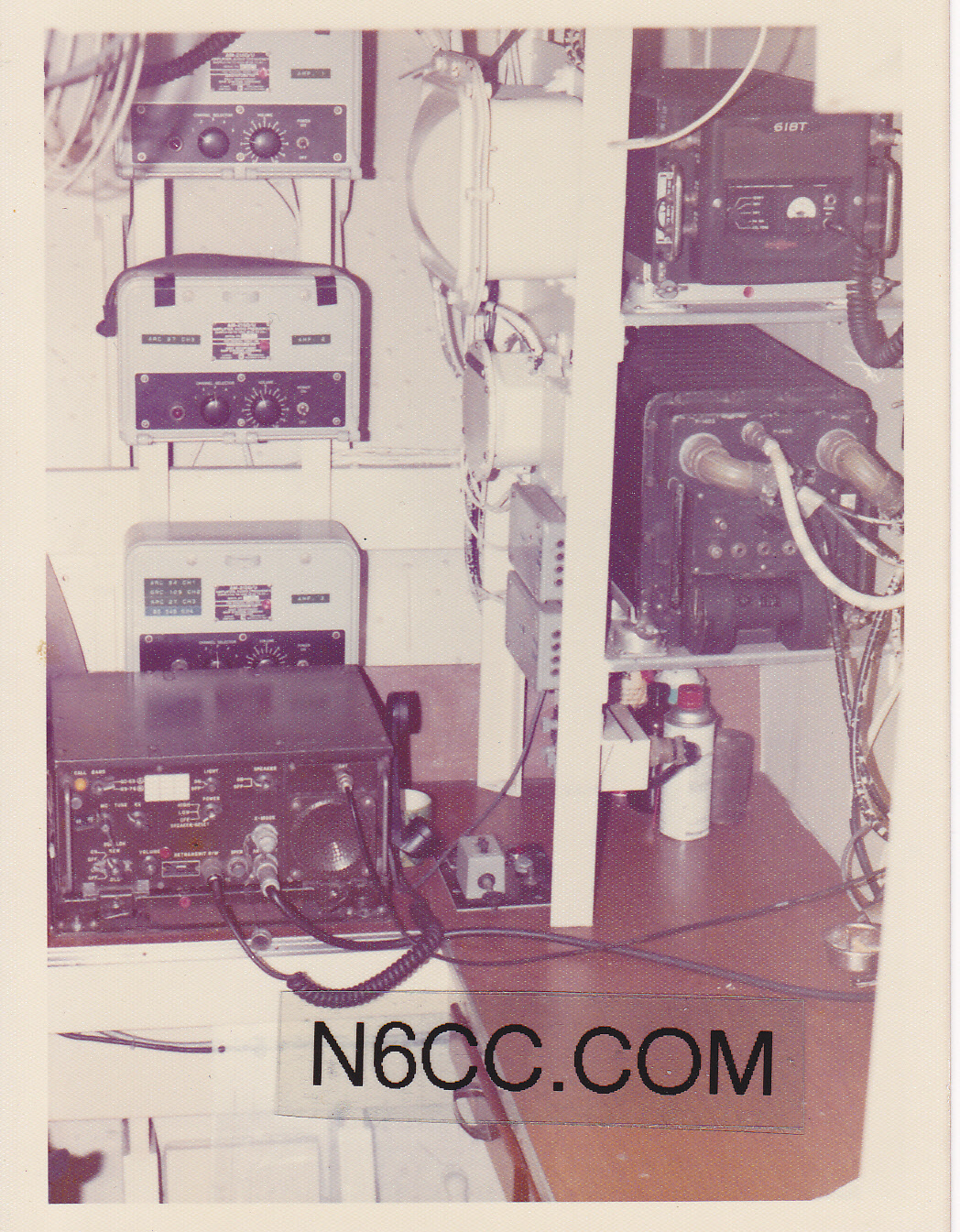

Note the green Dymo tape label on the lowest AM-215 amplifier assigning audio channel 2 to the GRC-109 system. The 3 amplifiers enabled simultaneous remote operation of 3 radio systems as needed. (My el-cheapo Instamatic camera from the Navy Exchange was working at its resolution limit!)
The GRC-109 installation makes sense since many of the MACV-SOG PTF missions in the Tonkin Gulf off North Vietnam were to insert and extract cross-beach commando teams that were primarily equipped with the RS-1 and GRC-109 sets.
The installed ARC-94 SSB/AM/CW sets on the PTF’s could not operate CW on split frequencies with the teams’ GRC-109′, so that type of comm channel is very understandable. See the Fast Patrol Torpedo Boats posting Fast Patrol Torpedo Boats (PTF-17) elsewhere on this website.
Most “US attributable” equipment was removed from the Norwegian-built Nasty PTF’s in the early phases of MACV-SOG’s OPLAN 34A. However in later years the GRC-109 sets were retained aboard the boats as a primary communications system for long range comms back to DaNang or elsewhere. Declassified Operational Summary documents do not note the difference between the GRC-109 and the RS-1 sets aboard these boats; such pedantic detail was not significant to the report authors at the time.
Below: A post-war (1975) photo of PTF-17 that was equipped with a GRC-109 set among other radio systems.

On the MACV-SOG PTF missions, the boats operated on split transmit/receive frequencies on these crystal-controlled CW circuits. It says a lot about the reliability and capability of these low powered morse code radio sets in that critical application. The declassified 1970 MACV-SOG Maritime Operations Summary report (Reference 7) noted the following freqs for CW with the GRC-109 (incorrectly identified as the RS-1 in the document):
Transmit/Receive:
4069.3 / 8217 KC Primary
4258 / 4632 KC Secondary
6220 / 3493 KC Tertiary
Split T/R operation would have been routine and it’s likely the Ops officers/OinC’s had authority to pick the best freqs for day/night operations, the “hot work” happening mainly at night. See Reference (7), MACV-SOG Maritime Operations.
It is interesting (distressing) to note that Reference (1) describes a 6-11 month delay in obtaining new crystals via the SOG Logistics Support Department in Okinawa. This is especially strange since the FT-243 crystals used by the GRC-109 were readily available from numerous US commercial companies for use by Ham Radio Operators for a few dollars each. These either from the massive WW2 surplus crystal stocks readily available, or custom made for specific frequencies on short notice, and still cheap. I bought lots of them.
One declassified CIA document that I have read stated that in the early 1960’s the CIA held over 12 million crystals in inventory. Something doesn’t add up. Crystals were readily available.
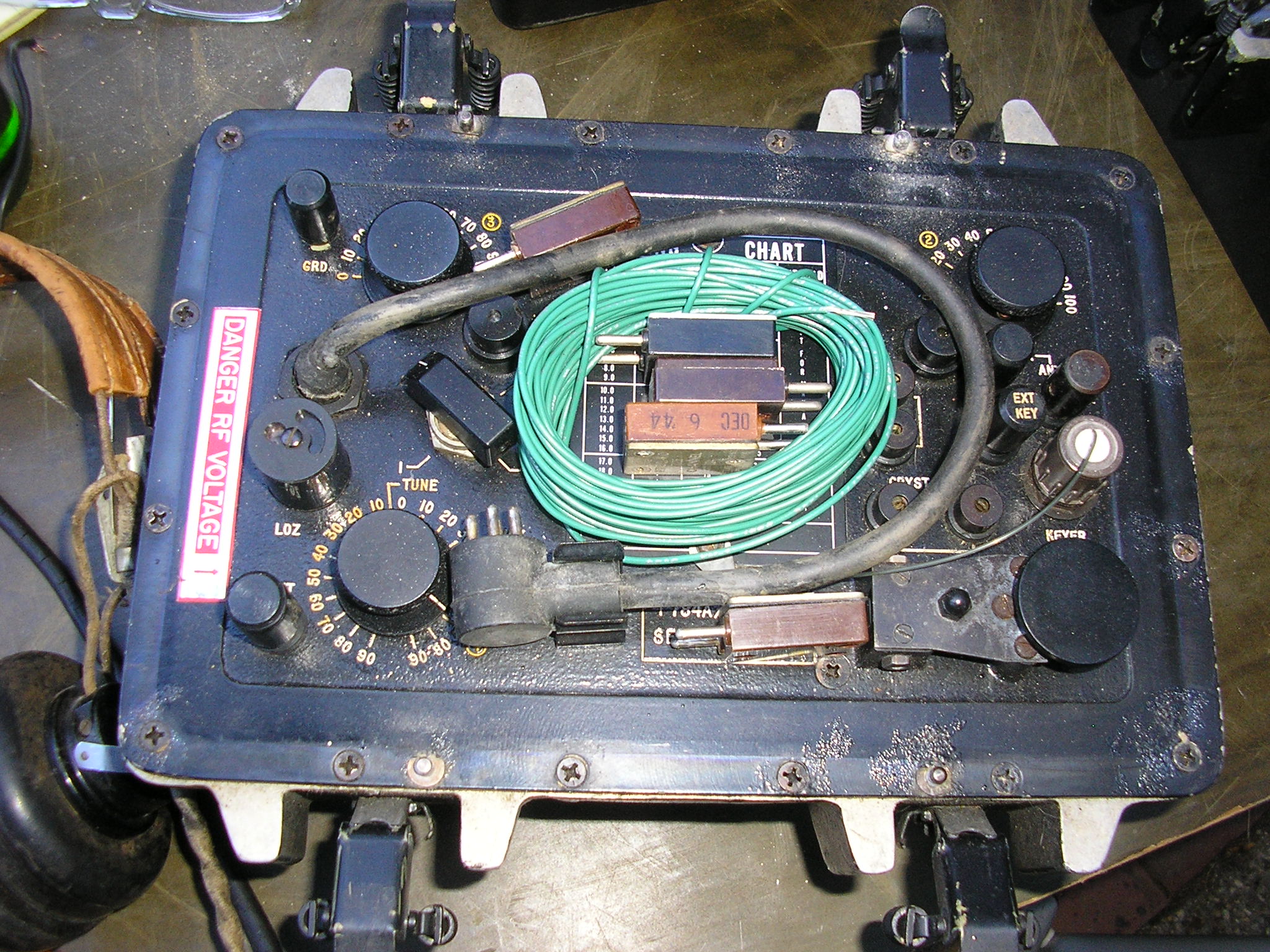
The T784 and RT-3 transmitters include provisions for 2 different types of crystals via independent sockets on the front panel.. The “upper” set accommodated FT-243’s but the “lower” set is designed for 1/8 inch pins with 3/4 inch spacing. That socket would fit crystals in the DC-11 holder format. But again, built-in versatility.
It is not known what the in-country inventory of spare crystals was available over this time period. Maintaining tactical comm circuits on the same frequencies for long periods of time is very dangerous but this delay implies that this may have been the case. In contrast, today’s tactical SINGCARS radios automatically change frequencies over 100 times every second.
Note the Tertiary transmit frequency of 6220 KC. It is interesting to note that frequencies between 5.0 and 6.5 MC were not recommended for operation with the AN/FRC-93 (Collins KWM-2A) radio transceivers used widely by land-based MACV-SOG units. (This was due to internal conflicts with the transceivers’ intermediate frequency amplifier systems resulting in spurious emissions in that band.)
So who would the tertiary circuit been with – who had something other than an FRC-93? NAD Da Nang (at Command and Control North) had URC-32’s – no problem, nor with any Navy ships. Someone, somewhere, sometime figured out this incompatibility. Just an interesting footnote. Or it could also be just a typo in the reference – there are many.
With a transmitter output of between 10 – 15 watts, a built in key that works well, versatile power supply options and a sensitive receiver, they did the job. The transmitter covered the frequency range of 3 to 22 MC in 4 bands; the receiver covered 3 to 24 MC in 4 bands.
Note that the frequency coverage is not the usual 2-12, or 3-8 mc of many tactical HF radios of the era. Those were intended to provide local or NVIS coverage over circuits beyond VHF FM sets, out to a few tens of kilometers or sometimes a bit more. The inclusion of the higher frequency bands in the RS-1/GRC-109 out to 22/24 mc is testament to the operational requirement for comms over thousands of kilometers in addition to more regional ops. That is telling.
In approximately 1969 the Army introduced the AN/GRC-109A, basically the same radio system however the A model had substantially thicker, heavier and stronger cases, carrying handles and it included a quick-remove cover with snap closures versus the screw-down types of the basic 109. Those snap closures would certainly speed up deployment and repacking the set after a comm period during a tactical move. I’m sure that was the motivation for eliminating the thumbscrew closures on the “Non-A” model. But at the expense of size and weight, speed is essential.
Once set up and wired together (no thinking required) they are quite easy to tune and operate. They are eminently usable “as-is”, no “mods” or “conversions” required or desired. In the hands of an experienced operator, they would get you where you needed to go comms-wise.
In addition to the GRA-71 CW Burst Keyer (primarily a transmission-security device; it is not a cypher machine), the GRC-109 and RS-1 could have also been used directly with standard offline encryption as well. This would include DRYAD pads, the M-209, One Time pads and other approved cyphers. Since those were available, it is not hard to guess that they saw considerable use as well.
This of course depended on the particular Op Area and transmission security considerations at that time and place. See Mark’s excellent site and his work with the M-209 and other related equipment NF6X.NET
Mark has also done an impressive job in decoding/demodulating the GRA-71 system with modern data acquisition and software techniques.
Above: the GRA-71 Code Burst Keyer kit (upper right) is seen along with the GRC-109 system. It is powered directly by the transmitter via the front panel connector which also carries the keying signal. (The big green radio in the upper left is the BC-683, a VHF FM Tank radio receiver from WWII; not part of the GRC-109 system).
In using the GRA-71, the operator manually keys in an encrypted morse code message on a magnetic tape cartridge. This tape is then used to drive a keyer connected to the GRC-109 transmitter – which then transmits the message at 300 words-per-minute (WPM). Obviously a shorter transmission than the usual 15-20 WPM message sent with the built-in, or external telegraph key.
Back at the Base, the received message is processed (by the GSH-17 system) and recorded on a magnetic tape, slowed down, tone shifted and then decrypted. To the enemy’s ears, it’s just a very short noise burst that is difficult to detect, tune in, record and most importantly, to locate with Radio Direction Finding (RDF) equipment. By then, the Team is gone.
I believe the GRA-71 may have been designed and built specifically for use together with the GRC-109, I can find no usage of the GRA-71 with earlier transmitters. The burst keyer of course was used with later sets such as the PRC-64A, PRC-74 (A, B and C models), TAR-224 and probably others.
The CIA also had its version of a burst keyer known by their nomenclature as the CK-8. I believe they would be otherwise functionally identical but further evidence that the CIA also used the GRC-109’s. More research needed here.

Above: The GRC-109A Model: T-784A transmitter, R-1004A receiver and “small” PP-2685A AC power supply set up ready to go. That speaker was inappropriate, but handy for initial checkout (where did I put those headphones?) With the receivers’ 4000 ohm output impedance, it will drive a 600 ohm speaker in a pinch. Improvise, adapt, overcome.
Note the separate transmitter and receiver wire antennas. This particular set was an old service veteran but it had been packed away for over 25 years since even those days. It fired right up. My right thumb can attest to that!
The GRC-109 / RS-1 was also used by Special Forces world-wide, outside of Southeast Asia, in the 1950’s – 70’s and likely beyond. But how far beyond? I have a BA-48 battery (also used with the GRC-9) with a Contract date of 1983 and a manufactured date code of May, 1984 (see below).
Fair Radio Sales was selling (“weak”) BA-48 batteries with 1986 date codes. (I am not aware of any other US radio sets besides the WW2 SSTR-5 and SCR-694 that used the BA-48.) It’s possible they were made under a foreign sales contract to support these radios being used by our allies. – Or not –
It is interesting to note that as late as August 1979 the US Army/Air Force manual on airdrop of supplies to Special Operations teams included packing instructions for the AN/GRC-109 sets (Reference 72). A load including 3 transmitters, 3 receivers, 3 power supplies, a G-43 generator and a (presumably gasoline) generator were illustrated on a pallet that also contained weapons, ammunition and medical supplies. It was dropped during “high speed, low level” approaches by C-130 aircraft using a 22′ diameter cargo parachute. Very rugged equipment available well into the “transistor age”.
It seems that operational experience with the GRC-109 and its relatives spawned some growth in this type of radio as technology improved. The mission-needs remained similar; the need for long range HF CW. The transistorized PRC-64 and PRC-74 and 70 came along shortly thereafter along with the hybrid TRC-77.
Another interesting set is the TAR-224 made by Avco in Cincinnati Ohio. This is clearly in the mission lineage of the GRC-109 but with the AM voice capability of the PRC-64 added – along with 12 volt DC primary power, GRA-71 burst keyer capability, bullet proof environment protection and an optional frequency synthesizer capability. 20 watts transmitter output and only drawing 50 ma on receive.
Covering 2 to 24 MC, it is fully transistorized, with a built in motor-driven antenna coupling network. It’s unusual “non-military” nomenclature and lack of much mention of it “in the literature” makes it all the more mysterious. Anecdotal references have it being used by the CIA well into the 1980’s.
I have learned that the Jet Propulsion Lab in Pasadena worked on a project to convert the AN/GRC-109 from its vacuum tube technology to an entirely solid state design. This information was provided to representatives of the Republic of Korea as part of a Technology Transfer program in 1970 (Reference 43). Presumably the ROK’s were using the GRC-109 then as well. I wonder what ever happened to that project. It may be possible that JPL’s design work eventually resulted in the TAR-224. More research needed…
Back to the ‘109:

The R-1004/GRC-109 receiver can be operated by itself using the BA-48 dry cell battery as configured above. In this application the transmitter would likely be powered by the hand cranked generator directly. The battery provides 1.5 VDC and 90 VDC for the receiver circuitry only. Here are the battery internals:

The 2 large cells are in parallel for the 1.5 volt filament circuit. The big stack of “A” cells (3×20 1.5 volt cells) are in series for the 90 volt B+ power. There are several sites on the Interwebs describing re-stuffing this package with C Cells and 9 volt batteries for use today. Viable originals are long gone.
The issued headphones are the H-65/U but any high impedance headset will work with the 4000 ohm output impedance of the receiver. Above: receiving with a set of High Z Brandes headphones; the HS-30 headset with the C-410 impedance matching transformer is also appropriate. It will also drive any 600 ohm headset or speaker in a pinch.
During OCONUS operations away from the supply pipeline there were commercial batteries available that were suitable. These were made by RCA and Burgess, providing 1.5 and 90 volts DC for the receiver. Foreign made batteries would also have been suitable; those voltages were common for battery operated receivers of that era.
Apparently they were reliable and quite successful in the Special Forces and “unconventional warfare” networks in Vietnam. Their use was favored as “long range and dependable” even long after they were being notionally “replaced” by the PRC-64 and PRC-74 radios. (The initial deployment of the PRC-74 began with 15 sets delivered to MACV-SOG in 1967 as an interim radio to the PRC-70 which came even later.)
In 1965, fifteen PRC-64 sets were evaluated by the 5th Special Forces group in the Mekong delta and central highlands of Vietnam and its performance was contrasted with the GRC-109. The report (Reference 40) stated they felt the PRC-64 was “far superior” to the GRC-109 for patrol (my emphasis) operations but it also notes that this was due to its smaller size, weight and easier set up. Critically important differences for a small, fast moving team operating in enemy held territory.
Capability wise, they were found to be equivalent by the Special Forces teams however they noted that the PRC-64’s 1.5 watt AM voice capability was unreliable. Just a few years later a MACV-SOG Communications Officers report in 1969 stated that the PRC-64 “is receiving little use but should be retained in inventory” (Reference 1). However, the future was becoming clearer – the days of the portable vacuum tube combat radio were coming to an end.
Due to their simplicity and all-weather ruggedness, I would assume the GRC-109’s were also more reliable than the AN/FRC-93 (AKA: a modified Collins KWM-2A) that SF was beginning to deploy for fixed-site work at SF camps. (That radio was also capable of SSB voice communications which the GRC-109 transmitter could not provide.) Especially when you consider that the FRC-93 required substantial AC power and associated generator not to mention the serious environmental protection absolutely required by them.
The GRC-109 could use a wide variety of available AC voltages and frequencies, a 6 volt wet cell vehicular battery or the hand cranked generator thus increasing its dependability in a combat environment. They were installed in the “commo bunkers” as a basic means of protection and operational security.
Referenced Antennas: The supplied antenna components for the GRC-109 system included the very basic AS-1722/GRC-109. It consists of a 100 foot spool of bare antenna wire with insulators, plus another 100 feet of rubber covered wire for the lead in/counterpoise etc. The recommended configuration was an inverted L approximately 30 feet vertical to a 70 foot horizontal section. Plus a “water pipe” ground.
Reference (3) states that as a protective measure in Vietnam the wire antennas were sometimes put inside bamboo “pipes” and buried 18 inches underground – and were still effective in communicating. It’s an authoritative reference but I will take it for face value, no mention of freq or operating range was noted. That’s an experiment I will try to duplicate this summer and see for myself. I’m a bit skeptical, especially during the “wet” season there. I have made contacts with mine using only a 1/4 wave wire laying on the ground – that works OK – but that’s a different story.
It is interesting to note that the 7th Special Forces Group ran an experiment with a GRC-109 utilizing a buried “multi wavelength” wire antenna. This was done in 1976 as FTX ORBIT QUIVER during a Defense Nuclear Agency high explosives blast effects test (“DICE THROW”) conducted at White Sands NM. The experiment consisted of 36 different field antenna configurations driving both GRC-109 and PRC-74B radios and exposed at an unspecified distance from a 628 ton high explosives detonation. So post-Vietnam, the Special Forces was still thinking about buried wire antennas for HF comms. Reference (71).
FM31-20, Special Forces Operational Techniques of December 1965 also describes indoor antennas for when they would have been operationally necessary. These are illustrated as vertical wire loops taped to interior walls of a room. Use with the GRC-109 is noted.


The SF Handbook also shows the inverted L as well as an off-center fed half wave wire deployment. I am sure operators improvised all sorts of better antennas for the tasks at hand.
Power Supplies: Powered by 75-270 VAC (40-400 cps), an optional 400 cps UGP-12 or Homelite gas fueled generator, 6 VDC from that captured T-54 tank battery or a G-43/GN-58 hand cranked generator, they could be used anywhere worldwide. Truly versatile.
The Homelite (TM5-6115-405-15) or UGP-12 “power unit” provided 115 VAC at 400 cps so one of the PP-2684/5 power supplies were also required when the generator was used.
The receiver could also be powered by itself from a BA-48 battery for those long watches on the Alert Net.

Above: The designers of the RS-1/GRC-109 obviously had in mind the need to use this set anywhere in the world under almost any conditions. The versatility of the primary power source options shows someone was not only thinking, but also had input from operational users.
They did their homework during the design review process. These options apply equally to the GRC-109 or the RS-1 sets. Image from the Manual.

Above: The UGP-12 gasoline powered AC power generator in a friends’ GRC-109 system. Rarely seen in the wild, this well traveled UGP-12 had been painted white some time in the past, along with its fiberglass carrying case, for reasons unknown. (Deployed in Alaska supporting Project Washtub stay-behind efforts? Or maybe at Ice Station Zebra?).
This 2-stroke generator was rated at 115 VAC, 400 cps, 125 watts. 400 cps was chosen for the generator (and the associated power supplies) to reduce the size and weight of the associated magnetics.
The CIA took delivery of 1000 UGP-12 generators between April and June 1954. These were intended for use with the RS-1 and RS-6 sets. Thirty three of those generators were transferred to the Signal Corps. (Reference 96.)
Subsequent post-1954 deployment unknown but the generator was an accessory as those sets replaced the WWII OSS SSTR-1 set with its similar (although 40-60 cps) AC gas generator.
The generator is acoustically, surprisingly quiet, starts easily and smokes very little. It incorporates a shielded ignition system to suppress radio interference. (The 2 small black boxes on the left side of the photo are unrelated to the GRC-109.) That little gasoline can is cute.
That little guy is also rated at 125 watts, 115 VAC at 400 cps. It was designed to power military radio in the field, notably the AN/GRC-109 and the earlier RS-1 and RS-6 CIA sets that were designed to operate off 115 VAC with AC sources delivering power at between 50 and 400 cps. Two-stroke engine, it will also power incandescent lamps or any other resistive load not to include motors or transformer operated equipment rated for 60 cps power.
That Genset is conservatively rated like most military gear. With its completely shielded ignition system and all metal construction it radiates no RFI noise into nearby HF receivers.

Above: The data plate as mounted on the generator. Standard stuff for a 2-stroke field generator. Note the absence of origin identity, manufacturer, contract data etc. Nothing to see here, move along.
Another generator designed to power the GRC-109 type sets is the Homelite XLA115/1/400 as seen in the Special Forces “inspection ready” photo up top and below.

When operating without the gas generator and when plugged into an electric lamp socket in that hotel “safe house” via a screw-in adapter, their low power CW would not even blink the house lights during those 0242 hours SITREP transmissions back to base.
Another power supply option was the apparently rare PA-109 (likely Power Adapter for the GRC-109) It is a 12 volt DC-DC solid-state power supply built by Nems Clarke. (NEMS, later to become Nems Clarke, was one of the 2 original makers of the RS-1 sets.)
The RS-1’s design with its RP-1 AC/DC power supply took into account the wide availability of 6 volt vehicle batteries common in the 1940’s to the 1960’s. The radio sets were now being deployed into the “12 volt era” of the mid 1960’s and beyond. The “large” PP-2684/GRC-109 AC/DC supply could be run from 6 volts via its vibrator circuity – but not from a 12 volt source. Hence the Nems Clarke supply which was a good solution to the battery availability problem “downrange”.
Service Life? Anecdotal evidence has GRC-109’s in Special Forces unit inventory as late as 1978. They were being overhauled at the Tobyhanna Army Depot as recently as 1983.
The Department of the Army Radio and Radar Reference Data manual, FM24-24, dated December 1983 still listed the AN/GRC-109 as “Standard A” issue. “Current inventory item available to fill operational requirements”. NSN 5820-00-892-0881 (Reference 36).
The set continued to be listed in US Army Field Manual FM24-24 Signal Data References: Signal Equipment dated 29 December 1994.
The defining specification for the AN/GRC-109 is MIL-R-55242 dated 21Oct1963 and was validated “for use in acquisition” by the Defense Logistics Agency 28May1986. The specification was finally cancelled “without replacement” on 21Dec1998.
On The Air with the AN/GRC-109 “in civilian clothes”
My GRC-109 probably retired from military service in the early 1980’s but it is still going strong on the Ham Radio bands with call sign N6CC. I bought mine from Fair Radio Sales in 1984. They first appeared in their Fall 1984 catalog suppliment, probably shortly after they were declared excess by the US Army. I ordered the set for $ 109.50 which included the transmitter, receiver and the large and small power supplies. I never get tired of playing with it and testing its capabilities from remote locations, operating it as intended.
My T784/GRC-109 serial 775 transmitter has a JAN CLRV 2E26 made by GE in Canada in 1965, the JAN-CG-6AC7WA was made by GE in 1964. This set was made by Admiral Corporation, apparently most or all “plain” GRC-109’s were as well. The contract for the GRC-109A models went to Oklahoma Aerotronics as I understand it. My R-1004/GRC-109 receiver Serial number 74 has tubes with date codes of 1965 and 1966, no markings or date codes on the IF transformer cans. I have no reason to suspect that these are not the original tubes.
The set is capable of running the receiver with crystal control – that works very well but the variable tuning works better for casual Ham operation. The TX of course is crystal controlled. Shown below running a coax-fed dipole for TX and a random RX wire launched into a nearby tree with a pine cone for a weight.

Above: A typical “camp” station of mine, here on the granite, up in the Sierra Nevada Mountains. Tracking and reporting submarine movements and suspicious canoeing activity on Caples Lake (or is it the deep water channel into Hungnam, North Korea?) in the background. The off-camera PU-181 rattling away generating AC power and also discouraging mosquitoes. A great campsite radio when you are well beyond cell-phone or repeater coverage. (This IS why you go camping, isn’t it?)

You can also use it to get the latest soccer scores from Radio Australia or coordinate your operations with a time-tick from WWV, BPM or RWM, depending upon your Op Area. Or just get a good laugh from Radio Havana Cuba on the shortwave bands; “Free Territory of the Americas” as they call themselves. Reminds you of why this type of radio was designed and employed in the first place. I wonder how many sets are cached in Cuba………..
My AN/GRC-109 field kit at another hasty campsite, below:
Below is the setup I used for Winter Field Day 2025. Here the set is powered by my DIY 12 VDC power supply via a solar-charged 12 V garden tractor battery. My buddy did not want to be the G-43 “cranker” ! I had the transmitter propped up in the case to allow easier access to the built in Key. The receiver had its own antenna; I made many contacts on 40 meters from Brannan Island with this Bomb Proof system.

As far as maximum range goes on Ham Radio frequencies, the GRC-109’s 10-15 watt transmitter is easily capable of inter-continental distances in the hands of an experienced operator and under good conditions. Especially so on the 14 and 21 MC Ham bands. Even with a simple dipole up a half-wavelength or a wire Vee Beam and aimed at your target station. It helps if you have a good CW operator at the other end and there are still plenty of them in the Ham radio ranks these days.
Just for fun, I had started on some very casual HF range tests during this period of low solar activity. In a 4 week period starting in December 2014 I had worked 30 states from Hawaii to Massachusetts, Alaska to Florida, mostly all on 7 Mc, with a dipole antenna. I’ll get most of the other states as I have time, but the east coast states may require moving to 14 Mc.
This transmitter is only about 1.7 “S” Units below a 100 watt transmitter at the receiving end but the main challenge is working with just a few crystals. I have to set up an “ambush” on my crystal frequency and wait for someone to show up there. It works, but slowly.. Calling CQ also works, but is of course, random.
I have worked Japan and South America from California with my set on 14 MC in the past. My best distance so far is 5674 miles to F6KNB on the French-Swiss border (on 7031 Mc). You can work pretty much anyone you can hear if the other guy is skilled.
On the higher frequencies the receiver selectivity/tuning rate is really the limiting factor in hearing the other guy, but above 10 MC or so the sensitivity starts to fall off somewhat as well. You need uncrowded conditions on these long range frequencies – generally not a factor in well-planned military comm circuits. On the 80, 40 and 30 meter ham bands, reliable CW comms are routine.
If you are working over an unfamiliar path or with different TX and RX equipment or antennas, you can use the online VOACAP program to help you get in the ballpark in finding the optimum frequency/time for that path. Select TX and RX sites, TX power, transmission mode, R and T antenna types. The Reverse Beacon Net is also excellent for measuring actual signal penetration on a given circuit.
VOACAP then obtains the current ionospheric sounding data for the path chosen and then it runs the calculation. This displayed data set clearly shows you what is “doable”, or not. Mission planning – It’s pretty good. Provides a graph of circuit probability versus frequency versus UTC time of day. I use it and find that it provides reasonably accurate predictions. The RBN gives actual, real-time data.
The GRC-109 (and me) in its element:

The transmitter will “load” (efficiently pump power into) almost any antenna, much like the RS-6. The GRC-109 however does utilize a Pi Network in the antenna circuit unlike the simpler RS-6 set.
I have powered up dipoles, inverted “L”s, random wires, a barbed wire fence, the rain gutters on the home QTH (stealth ops) etc. Above: Operating with a coax-fed fan dipole for 40/80 meters and a separate, random slant wire on the receiver. Works great.
Meanwhile: Back in the rear, with the gear and the beer…..

Above: Our setup during Electric Radio Magazines “Vintage Field Day”. Much more fun than the regular ARRL Field Day. Here we were running the GRC-109 along with a Command Set at a favorite campsite. We could switch the Command Set between 40 and 80 meters by just plugging in a different transmitter – the setup included both receivers. PU-181 generator, dipoles, slant wires etc. The power supply on the left powered the Command Set gear – no dynamotors in this system right now.

Above: Yep – it’s a cheesy photo – but this was Vintage Military Field Day as far as we were concerned. Makes perfect sense! That’s “Army Al” briefing our perimeter defense force.

Above: The GRC-109A station set up to take food orders while cabin camping at a remote Safe House. Smoked salmon beats MRE’s any time – even when heated with used one-time-pad sheets… Here, chatting with Don, W6JL on 40 meters CW in late afternoon – a 450 mile shot. My transmit antenna was a 33 foot wire thrown up in a tree; about 15 feet high, oriented mostly horizontally. The separate receiver antenna was similar.
The below photo is another favorite campsite further up into the mountains. Set up next to my cot, it kept me in touch from a place not covered by VHF FM repeaters and probably 40 miles from the nearest cell phone coverage area. My buddies just shake their heads – but then ask me how to go about getting a Ham license….So far, 9 of them have gotten theirs….

Fun Fact: One day up in the mountains with the GRC-109. That “hot pink” object in the background is an Army Signal Corps VS-17 visual signal panel laying on the rocks by the lake. They are used to mark friendly positions when working with Tactical Air or other friendlies in the area. We deployed it so that our camper buddies arriving late to the general area could locate our well-camouflaged position exactly from their avenue of approach. You can see these things in the bush from many miles away although this photo doesn’t remotely capture its brightness. It must be stressing the color filters in my cheap digital camera! In the sun, its a REAL attention getter.

In fact, it caught the attention of an F-5E Tiger II jet pilot flying out of NAS Fallon Nevada. It went overhead about 10,000 feet above us; the panel caught his eye so he banked and took a second look. He knew something “military” was going on – civilians don’t usually pack and display these panels in the wilderness; the pilot knew exactly what it was.
He made a wide, descending turn and then roared directly overhead about 500 feet above us in a hard bank to see what was going on. We waved, he wagged his wings. His F-5E was painted with Soviet camouflage markings and Red Stars – he was part of the “aggressor” training squadron at the Navy’s Top Gun school off to our east.

Above: F-5E “aggressors” in Soviet-style camo and markings (sans red stars); these 3 operated by the USAF. Official USAF Photo. No, they don’t carry GRC-109’s……
My buddies were bragging about how many fish they caught (I didn’t catch any as usual) but I caught a Tiger with MY lure !!
Come to think of it, I was running the GRC-109 at the time. Maybe the J-STARS aircraft controlling the fight from a hundred miles away detected my CW signal and then got an HF DF fix on my position. Maybe it wasn’t the panel……
So we then waited for the “duty” C-130 to parachute us a pallet of MRE’s, water, batteries and ammo but nothing showed up. Well, an airstrike didn’t show up either so I guess we called it a draw.
But I digress……
The only apparent operational shortfall of the GRC-109 while used on Recon patrols was their weight, assisted by the heavy GN-58 or G-43 generator (the transmitter and receivers are relatively light at 9 and 10 pounds respectively). Although substantially smaller, lighter and easier to pack than its predecessor GRC-9 at 32 pounds, it was still a bit heavy even though it was probably viewed as the latest state-of-the-art portable radio station at that time. (The GN-58/G-43, cables and accessories are common to both units for weight comparison purposes).
One online, second hand anecdote I have read stated that “Special Forces personnel that I knew said they routinely threw away the GRC-109’s in favor of the GRC-9” [sic]. Might have happened to someone, somewhere, sometime but in general I don’t believe it; it doesn’t make sense. I’ve not found any actual references to that kind of sentiment. I’m calling BS. Why?
By the 1960-70’s, the GRC-9 was already long in the tooth and the GRC-109 was specifically available for those types of SF operations, at least by US forces. You would most likely be crystal controlled anyway and wouldn’t need, or want, to deal with the complications of the VFO and Netting to a control station. You would rarely or never need or use AM voice; so why drag around the added weight, complexity and bulk of a GRC-9 in the jungle or forests or urban terrain of central Europe?
A separate GRC-109 transmitter (with CN-690 VR box) and receiver can be easily split up and packed by 2 men versus a heavy, bulky GRC-9 that can’t be subdivided. The GRC-9 is also not compatible with the GRA-71 burst-CW system either; that would be a critical shortcoming.

Above: The individual radio components are small and relatively light compared with the GRC-9 Receiver-Transmitter unit. Of course, the heavy GN-58 or G-43 hand cranked generator is a beast – but common to both sets while “mudborne”.
For casual Ham operation, and if I had no other choice, and if it was only at fixed sites, and if I didn’t have a good collection of crystals, and if I was not qualified in CW, if my “key” buddies were not CW qualified, if I didn’t have to carry it, if I needed to be vehicle-mobile with it, I’d pick the more versatile (for Ham usage) GRC-9 however. That’s a lot of “ifs”. For agent or mudborne, deep reconn operations during that era the GRC-109 would get my vote over a GRC-9, hands down. If I HAD to RELY on comms from The Bush, it’s the GRC-109 every time. Probably even today.
That said, it would still have been interesting to parachute with one of these strapped on (especially with the G-43 generator and seat) but that was routinely done (but not by ME!). The GRC-109’s were ultimately intended to be replaced by the PRC-74 (or PRC-64 in Special Forces A Detachments in Vietnam) depending upon the unit/AOR, but their use continued on throughout the US military.
(interestingly and similarly, the PRC-64 was an “adaptation” of the CIA’s Delco 5300 set for further Army use. Those 2 are nearly identical although the PRC-64 saw a short service life. Only 500 were made.)
Clearly, the GRC-109 were heavily utilized by the CIA along with its predecessor, the RS-1. One reference stated that they were routinely secreted inside the walls of selected apartment building rooms in eastern Europe for use by stay-behind personnel in case the neighborhood went downhill again. Any of you 05Bravo or 18Echo Vet’s care to comment?

The above photo shows my veteran GRC-109 appearing as an RS-1 set might have been cached under the floor boards in the attic of Der Funkspiel Hotel, on the corner of Lenin Street and Karl Marx Way in Budapest. This was just across the street from the Headquarters of the Soviet “Friends” T-54 Tank Regiment. Circa 1956. The brave Hungarians lost THAT battle but eventually won the war.
Well suited for transport as a “suitcase radio” it would be a bit heavy if it included the AC power supply as shown here. Not needing the ruggedness of the GRC-109, an RS-6 set would be better “suited” for this mode of transport and concealment.
By 1961 the CIA was issuing Samsonite suitcases for the RS-1 sets as a “Quick Reaction Radio Station”. Nothing to see here, move along.
Caches: Willing to bet there are many RS-1/GRC-109 sets still in eastern Europe, Asia or buried in various other interesting places worldwide. Someone back at “HQ” still maintains the freqs/times/callsigns/one-time pads and Comm plan in case any of these sets are ever retrieved and activated by OPLAN XYZ. Hope someone still knows morse code! All the best agents do, of course…..I have no doubt that these covert rigs will fire right up when needed.
A recent E Bay sale revealed that a complete RS-6 set was found in the attic of a building in the town of Tarrenz in the Tirol region of western Austria. That cache included a complete set of encryption/decryption materials (in German) and related items in addition to the RS-6 set, large NiCad batteries and spare parts. It was placed there in 1961 in a CIA effort to train, equip and support Austrian “Stay Behind” citizens in resisting a presumed Soviet invasion of Western Europe.
There were six known RS-6/RS-1 communications caches in Austria at that time. (CIA FOIA declassified reports, Project GRCROOND, Reference 48). Those same CIA documents clearly show that these equipment caches also included the RS-1 sets along with the RS-6 radios and a GN-58 hand cranked generator as well. It is clear from this declassified effort that the radio operators involved were trained in the use of both types of sets. Good backup redundancy planning? More to follow on that. For more information on the RS-6 CIA set and the Austrian cache contents, take a look here: RS-6 Transmitter Receiver Set
By 1948 a stay-behind organization was already being developed in West Germany as the Soviets continued to consolidate their gains in eastern Europe and East Germany. This effort was code named PASTIME; equipment included SSTR-1 sets and later RS-1 sets.
The Norwegian government also ran an active Stay Behind organization in that country, beginning in 1948. Known as “GLADIO”, it was jointly funded by the Norwegian, British and US governments well into the 1960’s but later on, solely by Norway. Many equipment caches were placed around the country for use by approximately 100 citizens groups to report on enemy occupation forces plus supporting partisan networks.
During WWII, intelligence teams operating in Norway reported back to the exiled Norwegian government in London. These agents were particularly effective in reporting on enemy forces occupying that country and were critical in the operations that eventually sank the Tirpitz battleship in a fjord near Tromso and the attack on the heavy water plant critical to the Nazi nuclear weapon efforts..
The Norwegians learned of the necessity of partisan teams operating in their own country the hard way… Communications were critical. Radios provided by the SOE and OSS were likely involved as well as indigenous equipment.
BTW, Soviet disinformation propaganda had a field day with sinister stories about the “real purpose” of these European stay-behind organizations once their presence became known to the general public. Of course accepted by Lenin’s “Useful Fools” in the west who sucked it all in.
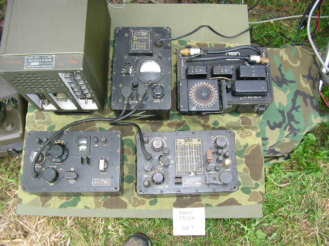
In the 1950’s and 1960’s the principal radio set utilized for these operation was the RS-1 seen below. Earlier caches may have included WWII allied and captured German equipment as available at the time. Later comm gear also included Norwegian-built equipment. (Reference 57).
Above: An RS-1 set recovered from one of the Norwegian caches. Note the CN-690 voltage regulator (lower right) for hand-cranked generator operation and the unusual red connectors at the power supply.

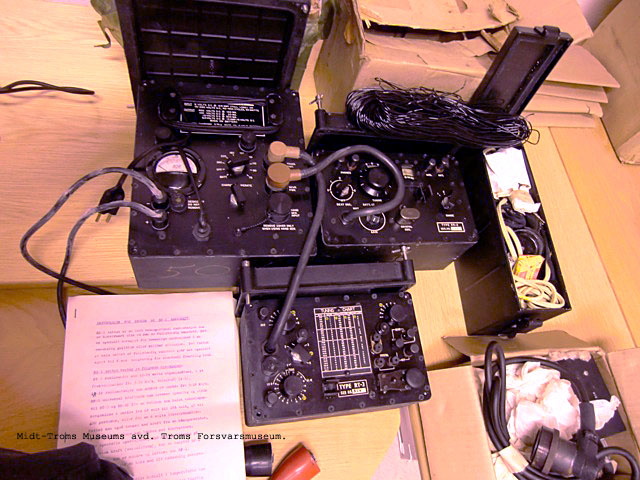
Above: Some of the packing materials from the RS-1 equipment cache now in the museum. The “liner” of the large wooden crate is made of lacquered sheet zinc, solder-sealed to protect the contents. Below is an older arms cache in Norway.

The above arms cache is probably from the late 1940’s and was buried underneath that rock pile in a remote mountain location in Norway. It contained a quantity of 9mm pistol ammunition and at least one 2.36″ M6A3 Bazooka round among other “energetic materials”. The supplies in this cache had long since degraded and it was subsequently “rendered safe” in-place by the Norwegian army.
It is likely that communications equipment was also cached in locations like this one. The very robust environmental protection of the RS-1 set would be ideal in a cache like this.
Above 3 photos from the Norwegian Troms Forsvarsmuseum Military History Museum, Tromso Norway.
Regarding the viability of equipment caches after long burial, an interesting CIA memo described the recovery of a cache in 1958 that had been buried in 1951. Location redacted. The cache contained a complete RS-1 set, 15 crystals, GN-58 hand generator, crypto materials, 6 pistols, 2 jars of ammunition plus spare parts. Upon opening, the equipment was found to be in “excellent condition”, the RS-1 set and all crystals “worked perfectly”. Good job guys! (Reference 61).
The RS-1 set was also used by anti-Communist Russian expatriates operating back inside the USSR in the early 1950’s. They received training in Germany (and probably elsewhere) and were then parachuted into Operational Areas as teams equipped with this set. The team package included a GN-58 generator modified for use while clamped to a tree or post. Their year-long training and preparation is described in the CIA FOIA declassified report EGMA-00713. (Reference 50)
In the US, Project/Operation WASHTUB also planned for “stay behind” personnel in Alaska to provide intel on the presumed Soviet attack and occupation of Alaska during the early “cold war”. These would be locals with intimate knowledge of the terrain, conditions, people and survival skills needed to live in rural Alaska.
Potential agents were approached, selected, trained and paid to perform as stay-behind citizens – Bush Pilots and locals with an Amateur Radio license was a prime consideration. The CW skills of Hams were a given in those days.
The source document describes notional communications with a submarine or a fixed station in a secure area. The document also mentions the use of one-time-pads. (Reference 35).
Would the RS-1 (or the later AN/GRC-109) been an ideal radio set for this type of operating in 1950’s – 60’s equipment caches in Alaska? I think so.
Above: A friends’ veteran GRC-109A transmitter ready for cover installation. Both the basic ‘109 and ‘109A sets have space under their respective covers for some small accessories. In this instance, 5 crystals and a 33 foot quarter wave antenna wire for 7 Mc operations. The receiver carries its own antenna wire under the snapped-on cover. There was also room for a small pencil, one time pads, trigraph and freq/time comm plan if you haven’t already memorized it.
Below is my trusty ‘109 operating “tailgate portable”. That big box of crystals sure makes life easier on the Ham Bands… This particular setup runs the “small” AC power supply, PP-2685/GRC-109 which is powered by a 300 watt 120 VAC sine-wave inverter installed in the Bronco. Clean, quiet power. The larger PP-2684 does everything the 2685 does but it can also be powered by a 6 VDC battery; it can also charge that battery.
For field ops requiring light transport, neither AC power supply is used. In that configuration the GN-58 or G-43 hand cranked generator in conjunction with the CN-690/GRC-109 is used between the TX/RX and the generator. The CN-690 contains an OB2 VR tube to regulate the RX B+ voltage – and is much lighter and smaller. The receiver can also be directly powered by a BA-48 battery.

Speaking of the 6 Volt-capable PP-2684 power supply. When running mine on a 6V car battery the vibrator RF “hash” basically wipes out the receiver – it was unworkable. May be just my vibrator? Any of you military, CIA or Ham operators of the GRC-109 been able to use the 6 volt power option successfully? If my power supply is representative, I would guess it was not very usable. Comments?
Above: Fixed-Mobile operation from camp, here running with a dipole in the trees as usual.

Above is a R-1004/GRC-109 Receiver being powered from a 12 Volt Gel Cell via a DC-DC Converter which solves the “continuous receive” power requirement when in the field. This version has the gray wire (off to the right) with a 4-pin plug to power the GRC-9 receiver as well.
Above: The insides of the prototype “BA-48 Simulator” as packaged for powering the GRC-9 and GRC-109 receivers. Compact, well shielded when the cover is in place. Provides 105 VDC and regulated 1.4 VDC from a 12 volt input. Built from available, “non-optimum” parts, it needs a PC board layout next…
I am currently developing a similar 12 Volt power supply to provide the 450 VDC B+ and 6.3 VDC to the transmitter. This will be an updated, functional version of the elusive “PA-109” DC-DC power supply built for the GRC-109 by Nems Clarke late in the life of their employment.
This very elusive device was powered by 12 VDC primary power for use with the new, emerging standard 12 volt auto batteries. I have only seen a photo of one, I have never seen one in the wild.
I know it’s considered Blasphemy to use any military radio with “non-issued” accessories like this. However, I use this radio pretty routinely at campsites and I needed something “12 Volts DC” and practical when not going the “entirely military experience” route. The PP-2684/GRC-109 AC power supply can also run from 6 VDC but it is big and heavy and also requires a big, 6 Volt battery; somewhat rare these days. Then there is the vibrator hash noise as mentioned earlier. Not practical for my ops. So here we go!
UPDATE: Sometimes you can’t find a particular piece of useful or interesting surplus military gear, so then you have to build your own. When complete, I will integrate both the TX and RX supplies into a single unit for use in the field when running off a 12 volt garden tractor battery. See the “Design and Engineering Projects” Category from the list on the right for more details on the receiver power supply.
“To invent … you need a good imagination. And a pile of junk.”
– Thomas Edison.

Above: The beginnings of a packaging job for a 12 volt DC-DC power supply to power the GRC-109 transmitter and receiver in the field. The breadboard prototype is working well. This supply will also be able to power my RS-6 set but as usual, the unobtanium connectors are a challenge – I’ll go with cable adapters. The case is a spare case casting for a GRC-109 transmitter. There will be enough room inside to include a GRC-9 transmitter B+ power supply off in the future as well. First I would have to find an elusive GRC-9 female chassis connector to mount on the side of the box.
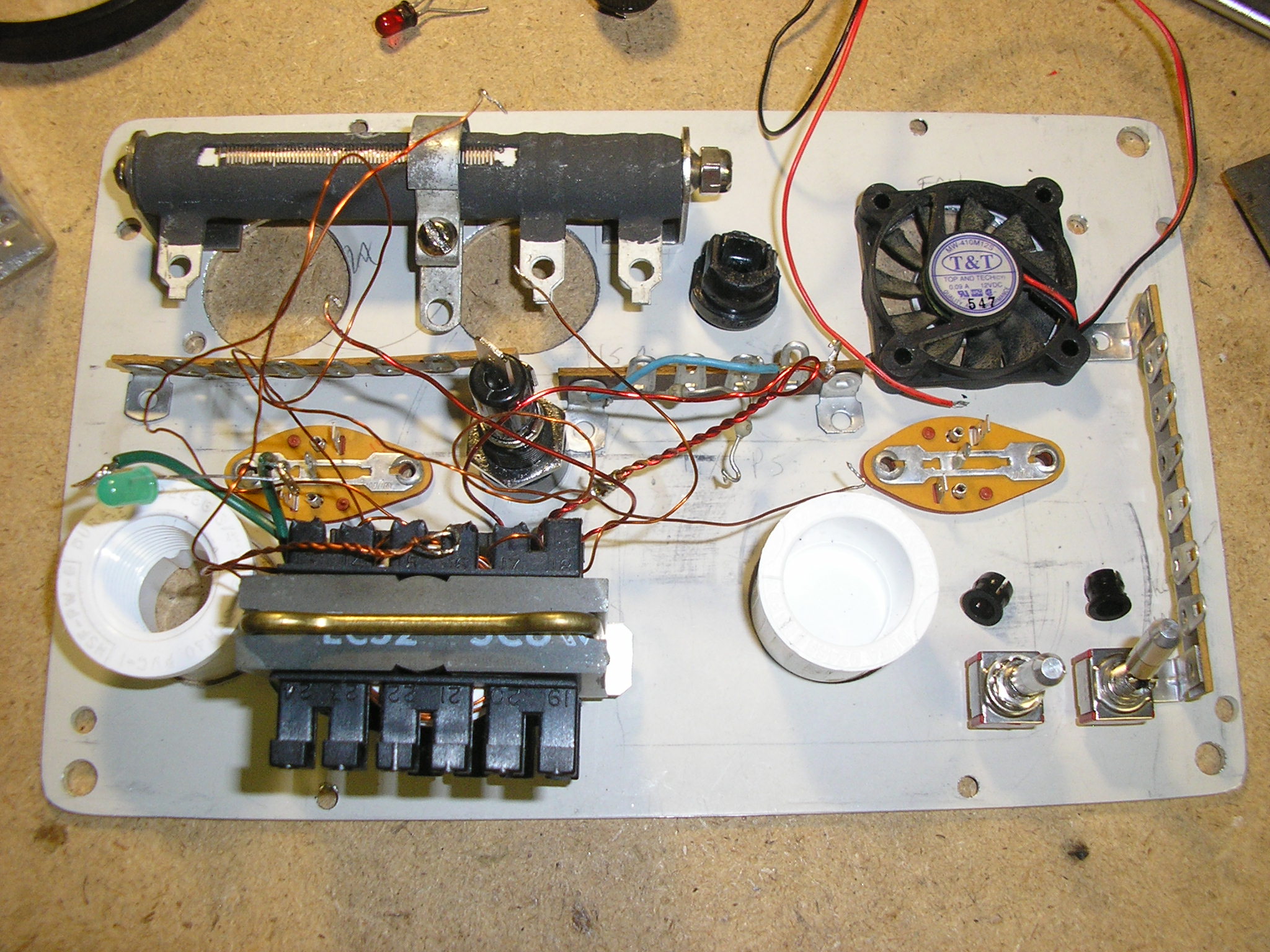
Above: Will everything fit? Some initial layout planning. Almost everything that went into this power supply except for the case, PVC pipe fittings and some molex connectors came from the junk box (whose parts availability drove the design). Total parts cost: about $20 but about 3 weeks of design, fabrication and testing which is the “expensive” part.

Above: Yes, it all fits, with room to spare for the future HV B+ supply for the GRC-9 transmitter as well.

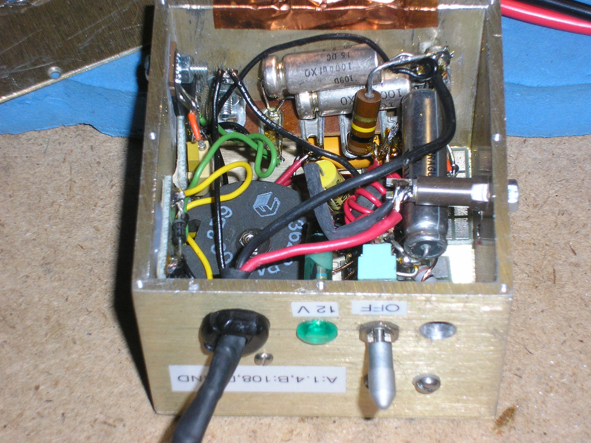
Above: The prototype GRC-109 power supply powered by 12 Volts DC. The standard issue cover screws into those corner holes for transport and storage, just like the other GRC-109 components. It provides 1.40 VDC regulated filament power, 6.3 VDC, 102 VDC and 425 VDC. It is built around custom-designed, high frequency ferrite core transformers and the usual standard power supply parts. A basic “brute-force” design….No fancy “SMPS” technology here – that stuff hurts my head.
The design is based entirely upon the magnetics of the HV transformers, and that NOS core material, bobbin and form factor are what I had available (the transformers should ideally have more primary and secondary turns but I was limited by bobbin space).. As a consequence, replicating this supply would not be simple – it strongly depends upon these transformers and their resultant frequency of oscillation, turns ratios and efficiency. The final design is the result of much experimentation beyond the “math”. If you are good with high frequency ferrite core transformer design, this would be a good starting place.
So that project is coming along. I have built the power supply into the former GRC-109 transmitters’ cast aluminum case and then installed the receiver PS module inside as well. The 12 gauge power cable with Power Pole connector rolls up and stashes inside the screwed-on protective cover. It is working well – the transmitter delivers 13 watts of RF into the antenna while powered by this supply and it sounds very clean, T9. I have included a small fan to keep it cool for any further expansion for the GRC-9 transmitter B+. It is not needed now, it runs only slightly above ambient temperature.

Above: The DIY power supply powering the transmitter and receiver. The RX and TX supplies are electrically independent so I can just monitor with the receiver when no transmissions are necessary – saves battery power before the “receive” Comm Window time arrives.
With both supplies running and the transmitter “key down”, it draws under 5 amps. With the receiver alone, it draws 800 ma. So with the low duty-cycle of CW, my little 12 volt garden tractor battery will power the system for at least a week of casual field ops – even if I don’t bring the solar panel.
As a bonus, the GRC-9 receiver can also be directly powered by this supply simply by plugging in the GRC-9 battery cable into the front panel receptacle. The GRC-9 transmitter upgrade inside is next on the list. Circuit details are posted here: http://www.n6cc.com/grc-9-grc-109-receiver-battery-power-supply

Above: The DC-DC power supply can run the receiver and the transmitter simultaneously. While using a small Gel Cell as above, the transmitter is powered by the G-43 generator with the battery only powering the receiver. That small battery will power both but you could not make many long transmissions before the little battery would need recharging. Solution: Use a larger battery like a Deep Cycle garden tractor or marine battery instead. With a small solar panel you are operational indefinitely. OK, lets try that….Off to Military Field Day 2014.

Above: The first power supply shakedown operation in the boonies. Here running a small 20 watt solar panel charging the garden tractor battery. This powered the GRC-109 with the new DC-DC power supply for a 4 day operation in the mountains. This setup would run a forward operating base indefinitely, its pretty quiet – and easy to set up and transport while tailgate camping.
The system worked well, plenty of capacity. I worked a bunch of guys in California on 40 meters CW during the day; 500 mile shots are no problem. Just a hint of power supply oscillator harmonics up in the HF band around 9 Kc apart and they drift around a little until the PS warms up for a few minutes – then they stay put – and are not a bother. Not much above the noise level. A snap-on ferrite choke on the 12 V power leads drops it considerably – but I forgot to bring that…No problem….
The long orange power cord to the panel allows me to move the panel into the sun without having to move the equipment. I also brought along my homebrew charge controller with its metering capability. Not really needed since the 1 Amp full sun panel cannot overcharge this battery. But the metering makes it interesting…

Above: Another miserable day in the mountains…..Elevation 7550′ AMSL about 40 miles north of Yosemite National Park; mid June.
Steaks and trout cooking…..Time for Radio Silence.
Night Ops:
Above: Working Field Day 2015 with the GRC-109 and the new 12 VDC power supply running off the garden tractor battery. Lots of contacts with the “by the book” 100 foot inverted L wire antenna on the transmitter, a 50 foot horizontal wire for the receiver. That’s the TRC-77 in the ALICE pack off to the right.

Above: Military Field Day 2018 with the 12VDC power supply. Off grid in the Sierra Nevada mountains CA.
——————————————————
My set came from Fair Radio as have all others that I know about. Mine worked “as shipped”. It has obviously seen a lot of operational service, it’s pretty scuffed up but being indestructible, keeps on going. None of the serial numbers match but some of the units have an interesting pale green lightning bolt stenciled on them (see power supply in the “suitcase” photo, above). Wonder who that unit was….
Phil at Fair Radio told me they had obtained all their GRC-109’s from the Tobyhanna Army Depot in Pennsylvania when the Army eliminated them from inventory. “Hundreds” of sets were obtained by Fair but none came directly from overseas sources. Tobyhanna was apparently the Army’s item-manager for this system. Fair said that they sold quickly, mostly to US customers but some went overseas.
This was before the US decided to “demilitarize” surplus comm gear prior to release as they are doing these days. Thankfully the GRC-109’s were spared that fate but I know of some real horror stories of equipment getting into the wrong hands back in those days. But then again the US DOD is not in the business of keeping a small group of old radio collectors happy – even though we paid for this gear…..
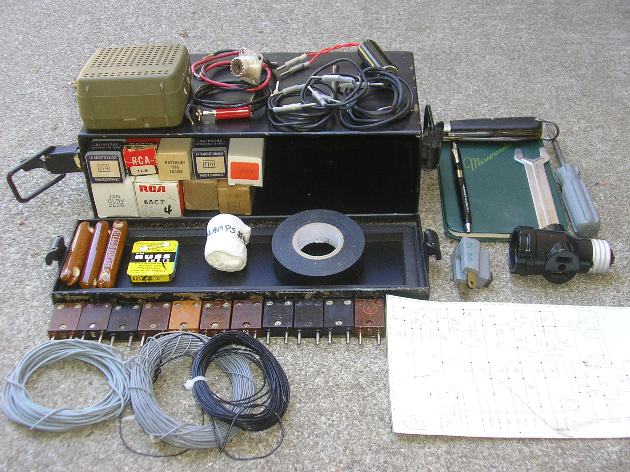
Above: The Maintenance Kit, Electrical Equipment MK-833/GRC-109(Mod). This kit with its watertight snap-on lid contained spare parts for the radio set. The original set included a complete set of spare tubes, fuses, lamps, screwdriver, needle nose pliers, TL-29 knife, 2 wrenches, 6 antenna insulators, power adapters, vibrator etc. All contained in the Case CY-4621/GRC-109. There is plenty of extra room in the case for crystals, antenna wire, and interconnect wires. This box is unmarked; probably of CIA RS-1 origin.
My kit is not yet complete – still working on finding some of the original parts including the original insulators, battery clamps, pliers. I have a complete set of spare tubes. I have modified the contents by adding a few experience-gained accessories; this kit will keep me going for a long time.
The “Mods” include power adapters, jumpers, external key/headset adapters, an official USGI Memo pad with “Skillcraft” ball point pen, tape, coax adapters, wire antennas, a small “amplified” speaker, and a set of laminated schematics etc.
Like the radio sets themselves, this case could be buried in a swamp indefinitely – good sturdy gaskets and firm snap closures. This kit will also support a GRC-109A and RS-1 sets; this kit will also support an RS-6 set by substituting the appropriate tubes.
Absent this issued box a 7.62 mm Ammo Can would make a great spares kit package.

Maintenance kit with some operational accessories packed out, ready to go.
The GRC-109/T784 Transmitter:
One unfortunate, and often discussed design “quirk” is that the receiver is somewhat starved for antenna signal when a common antenna is routed to the receiver through the transmitter during “key up”. (The CW key contacts “short out” the receiver antenna signal to protect the receiver on transmit; this to enable full “break in” – QSK – operation and especially to keep things simple with the use of a single antenna.) So far so good.
However, a quick look reveals that the receiver antenna coupling capacitor in the transmitter (C-14, an 18 pf silver mica) is much too small to couple significant common antenna signal to the receiver particularly at the lower frequencies (below approximately 5 mc per the RS-1 Manual) and especially when using a high impedance wire antenna as specified. Increasing C-14 to say, 500 pf or greater makes a definite receive improvement.
However the transmitter circuit cannot tolerate an increase of that size since that same capacitor is in parallel with the pi-network variable loading capacitor(s) when the key is depressed. That completely restricts the impedance matching pi-network range. A big capacitor won’t work but it certainly helps the receive signal at lower frequencies (I tried it).
The manual recommends a separate receiving antenna when working below 5 mc.

So that 18 pf value was a design compromise – a small enough value so that it doesn’t overly constrict the transmitter antenna matching range with a fixed capacitance – but big enough to pass SOME antenna signal to the receiver on the lower frequencies.
As a secondary “system” issue, when receiving (Key up), the variable 200 pf TX output load capacitor C16 (and C15 as tuning requires) are now in parallel with the combination of C14/C4 and the receiver input. This effectively shunts the majority (up to 95%) of the received signal to ground since the reactance of C16 (+C15) is much lower than that of C14. They present a “low” impedance path to ground in parallel with the receiver, therefore a big signal loss. (“Suck Out” is a term sometimes used for this loss, whatever the heck that means.) They are just passive, reactive circuit branches in parallel to ground.
This component/network compromise was probably viewed in the context of the overall “systems design” for these radio sets. On operational missions they would most often be receiving a transmission from the “Base” station – which had big antennas and was running a high powered transmitter like the URC-32, GRC-19, GRC-106, FRC-93 etc. On tactical operations, those should produce an adequate signal to the GRC-109 receiver even with the above losses.
Also, getting the transmitted information OUT from this long range Recon team would generally be more important than getting information IN to them. An all-important attribute for the recon team is simplicity and ease of setup – as in deploying a single antenna.
The RS-6 set does not have this problem, but it uses a T/R relay to isolate things, the ‘109 does not have a relay. Modification by installing an internal relay or a PIN diode switching circuit would be simple, but I chose not to go that route. As a result, I usually run mine with a dipole or inverted L on the transmitter and a random 50’ wire connected directly to the receiver. Works great for casual Ham operations but it takes a little more setup time, generally not a good solution for a fast moving tactical unit..
Another ‘109 transmitter oddity is the placement of the B+ HV feed (via RFC L-9) and the DC blocking/RF output coupling capacitor (C-13) on the antenna end of the pi-network inductor. This places HV B+ on the Pi-network inductors and switches. Those are “normally” placed at tube-end of the pi-network. Wonder why the designer did that..
The transmitter crystals can be on a fundamental frequency or doubled/tripled for the higher frequencies. Multiplication comes at the expense of power output however. No mention of this in the manual. As an experiment, I tried (successfully) to drive my transmitter with a Heathkit HG-10 VFO to see if it would work. More details on that experiment here: http://www.n6cc.com/angrc-109-rs-1-transmitter-with-vfo In a pinch, when your Comm Window approaches and you can’t find the right crystal, this will work pretty well at your Base Station.

Above: Driving the CIA’s RS-1/RT-3 transmitter with a vintage Heathkit VFO on 40 meters. This will also throw off enemy SIGINT intercept – they will detect the slight VFO drift and deduce you are not using a crystal-controlled RS-1/GRC-109. You must be someone else…They are everywhere Tovarish! Could come in handy… Hi Hi.
The GRC-109A model uses the “snap hasp” method for connecting the cast aluminum covers to the beefed-up radio cases. Very strong but very heavy and it makes each chassis quite a bit bigger – I prefer the thumbscrew hold-downs of my plain ‘109 better although they can be tedious if done frequently. The snap hasp closure was likely provided in the “A” model based upon user feedback from fast moving ground units that had to set up, transmit their traffic, repack quickly and then relocate while in the field. Maybe that hasp modification was faster but it caused more unintended consequences. The plain GRC-109 also fit inside an ALICE pack better.

Above the spring-loaded carrying handle of the GRC-109A. The “A” model units seem to be particularly dense – small AND heavy. The larger 109A cases add a lot of weight to the basic GRC-109. The handle comes in, well, handy.

Above: A size comparison between the modified CIA’s RT/D-3 transmitter with the GRC-109A transmitter. Those hasp mounts, protective bosses and covers make the 109A appreciably larger, noticeable while trying to jam it into a field pack. The RT/D-3 transmitter is the same physical size as the GRC-109 transmitter (T784).
The RT/D-3 variant is the RT-3 but modified for the use with the GRA-71 code burst keyer. This one is stamped MWO-(39?) which may have added an RF choke from the antenna PI network to ground. (safety feature in case the output coupling capacitor C-13 fails, putting HV B+ on the antenna.) Your Assistant Radio Operator will appreciate that.
A few GRC-109/109A transmitter “features” are noted. The transmitter antenna output tuning indicator is a #47 lamp across a 20 ohm resistor, this in series with the output to the antenna connector. This is really an RF current monitor since it is in series. While running antennas with high impedance input, there is little if any glow from this lamp although RF power is being delivered to the antenna. A 1/2 wavelength (or integer multiple) wire is an example. It is then difficult to tune the transmitter by looking at the lamp – which isn’t glowing. Some Internet commentators attribute this effect to “erratic operation” or “it won’t load some antennas”. Wrong.
To solve this, I carry an NE-51 neon lamp with leads soldered to it; I then place this from the antenna connector to ground, thus serving as an RF voltage monitor since the 10 watt transmitter is developing a high voltage in this situation. The NE-51 breakdown voltage is around 65 volts peak, RF. This will glow with the above antenna since the input impedance to a 1/2 wave wire is greater than 400 ohms. I also use this trick on my SCR-284 transmitter as well. Handy. (You can also facilitate tuning a high impedance antenna with a field strength meter such as an ME-61/GRC.) With low impedance antennas (like a dipole or a 1/4 wave wire) the installed #47 glows brightly when tuned. Carry spares….
Be careful, this transmitter will give your finger a memorable burn if you touch the antenna post or the lead protruding through the post while you are adjusting the nearby Tune control! Note the “Danger High Voltage” foil sticker on the GRC-109A transmitter pictured above. It has a red arrow pointing to the antenna connector. A lesson learned and acted upon! Hint: Don’t push the antenna wire all the way through the post – halfway is just fine and you finger will appreciate it. Or….
Introducing the ThumbSaver 2000: Your fingers will appreciate it and you won’t compromise your hide site location with loud swearing when you zap your thumb.
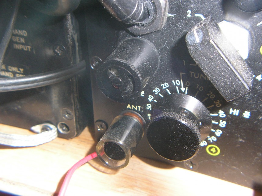
Above: A simple guard made from a 3/4″ piece of 1/2″ I.D. soft vinyl tubing. Poke a hole in the side for the antenna wire. The wire does not go all the way through the post, out the other side. Instant finger protection, especially in the dark. Thanks to one R.F. Burns for that idea.
The GRC-109/R-1004 Receiver: Radio Art
They are extremely well-built. Mine is in pristine condition internally despite an external case that speaks of heavy military use. The environmental protection of this 60+ year old equipment is superb, not even a hint of corrosion inside. Note the thick neoprene gasket around the front panel interface and the red glyptal sealant on the screws that penetrate the panel from the outside. Looks like the 3 section tuning cap rotor/stator is silver plated. No Tin Whiskers here!
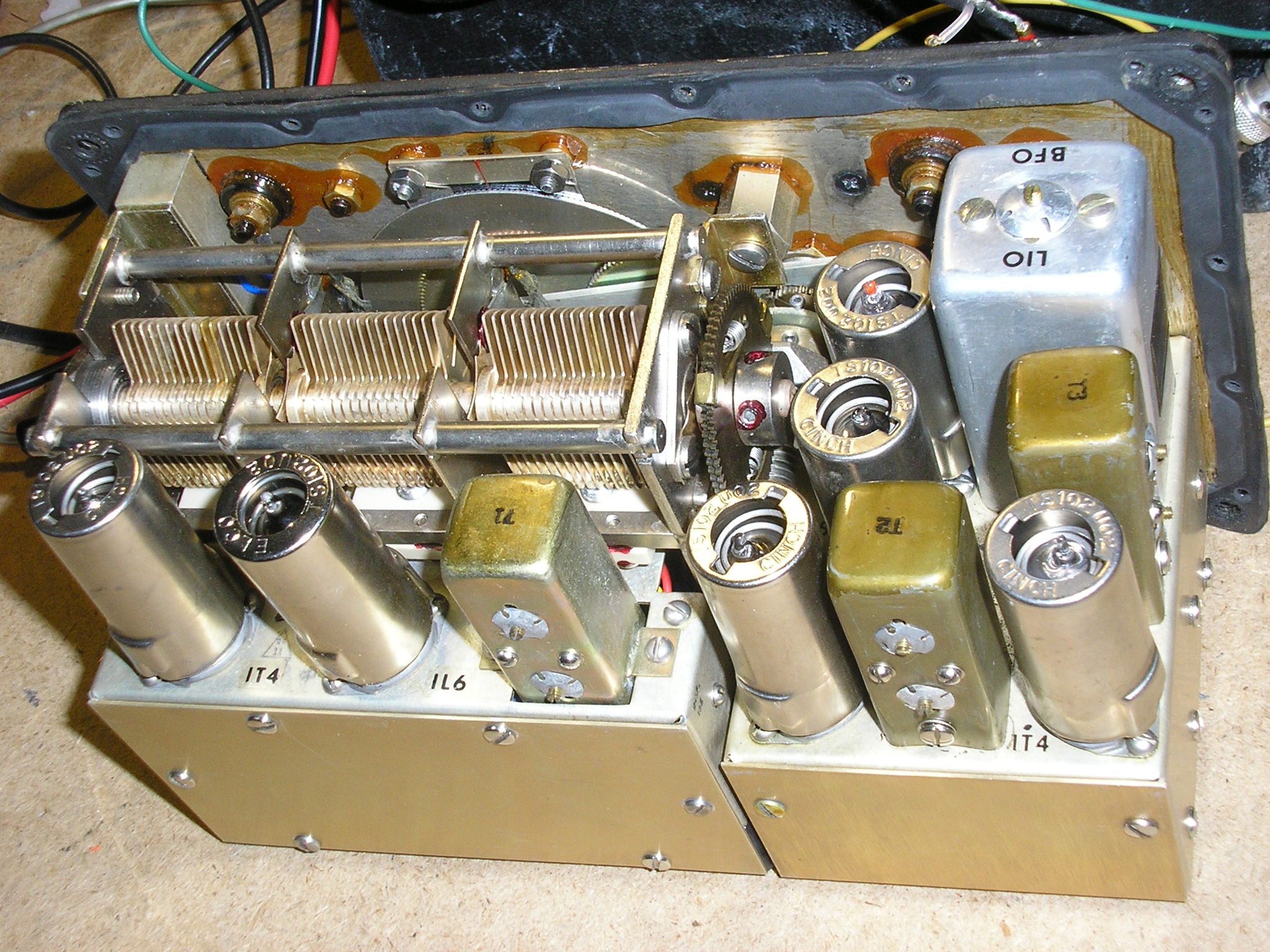
Like the transmitter and power supplies, the chassis is not MFP’d (moisture fungus proofed), a testament to the designers’ faith in the panel and control gasketing and silica dehumidifiers. This makes it easier to work on if you ever need to do any internal soldering (I haven’t). Also note the generous number of stainless steel front panel screws to hold it together. When opening one of these sets up a powered screw driver is your friend!

I used a red, green and blue felt-tipped marker to color in 3 of the tuning knob’s white “index” marks. A little hard to see above. These assist in returning to my favorite TX spotted freqs while utilizing the logging scale and the 0-10 “vernier” scale. Here tuned to 7050: 38 on the logging scale + “Blue” 6 1/2 on the tuning dial. Or more simply “Blue 6.5”
Easy to get back on freq quickly once I am already in the band segment, especially after some band-cruising!
As with nearly all comms receivers which disable the AVC line when the BFO is turned on, the R-1004/GRC-109 does not even have an AVC/AGC circuit since it is primarily a CW receiver. You may have to ride the manual “Gain” control in the presence of strong signals. I have not found this to be a problem when operating up in the mountains – few really strong signals to contend with (no locals !).
However, the set does not incorporate a means to generate a sidetone signal so you can’t hear your own keying very effectively. Since the receiver does not effectively “mute” during key-down (only the receiver antenna terminal is grounded via the CW key when using a common antenna), you can hear your own signal but it seriously overloads the receiver.
That’s especially the case when using a separate receiver antenna. Then, you must turn the Gain control all the way to minimum to (maybe) produce a usable sidetone. (Large excursions of the Gain control can pull either the BFO or local oscillator a few KC’s.) A bit of an annoyance if you are used to having KenYaeIc appliances do all the fun stuff for you.
In typical military comms applications you would likely be transmitting on Freq X while receiving on Freq Y, therefore loosing the ability to monitor your own signal anyway. Takes some getting used to – just “feeling” your fist via the key; that’s a training issue. But then again, you are using the GRA-71 Burst Keyer to send your operational traffic aren’t you? Then, a non-problem.
The receiver IF bandwidth is 9 KC at the -6db points; broad but adequate for its intended purpose on CW, sounds good on AM. For an operator working under pressure, tuning for the target transmitter does not have to be precise to get the job done. On 40 meters the dial tuning window “indicator” line is about 9 KC wide. Sort of a graphical representation of the bandwidth that you will be receiving!
The receiver has a single “Gain” control. This control varies the grid bias and hence the gain of the RF amplifier and the first and second IF amplifier stages. The AF amplifier operates at a fixed gain setting. For a simple receiver, this needs to be understood as a compromise where separate RF/IF amplifier gain and AF stage gains are independently variable as in the GRC-9 receiver for example.
So operationally, you may have to turn the Gain control high enough to hear a weak signal but in the process cause the signal to now over power the BFO injection in the detector circuit. It’s a tradeoff and part of the “character” of the set. I wouldn’t want to try to compare it with receiver technology of 60 years later. But then again, the new gear wasn’t designed to be buried in a swamp either.
If you want to go the unauthorized “luxury” route (or to put on a demonstration for uncleared visitors), use the receiver to drive a simple “amplified” speaker with its own Volume control. Then you can adjust the Gain control for best reception and detection performance. Then vary the speakers’ amplifier volume control to an appropriate level. While “unauthorized”, this simple combination makes a major improvement in receiver “system” performance.

Comm Center, Forward Operating Base (FOB) “PIGOUT”
Above is the basic field setup providing us with reliable comms from a very remote off-grid location. The TX and RX were powered by the “small” PP-2685 AC power supply and a gas-driven generator, the G-43 standing by. TM 11-5820-474-14 (18MAY1962) indicates the use of the G-43 hand cranked generator. However the G-43 is functionally interchangeable with the GN-58 and I am not sure when the change from the ’58 to the ’43 occurred. Still looking for a reference on the GN-58 configuration.
We were running a coax-fed 40 meter dipole up about 15 feet with a separate 64 foot wire for the receiver. Folding stool and big crystal collection optional while on operational missions.
“WHEN ALL ELSE FAILS – THERE’S HAM RADIO”
“WHEN HAM RADIO FAILS, THERE’S THE GRC-109”
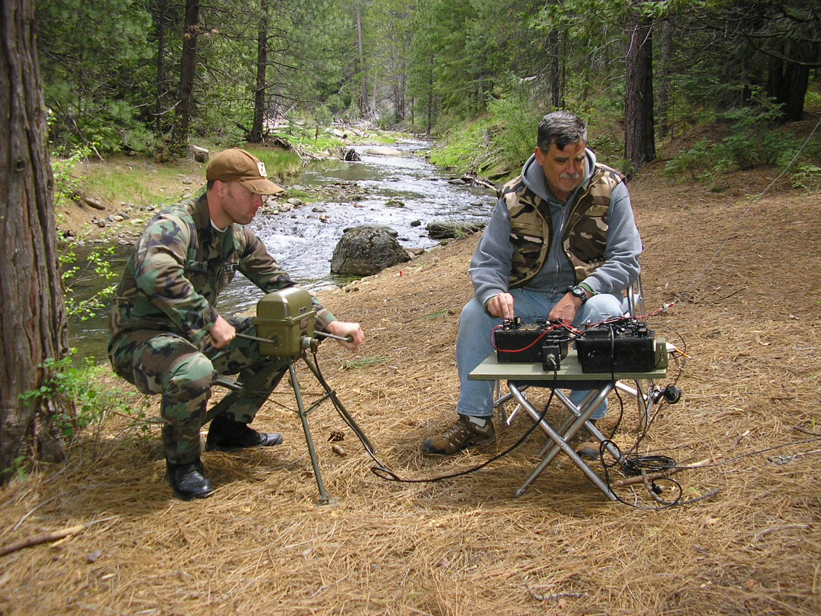
Ditty-Bopping in the Mountains. Sending Morse Code with an effective, reliable radio. In any Clime and Place…. Powered by a handy Marine who happened to be in the area……
Above is the same system in action, as used to work WA6OPE on 7050 KC at 1300 Local, a 120 mile shot, human powered. Good daytime signals with GRC-109 sets on BOTH ENDS of the contact.
Here we were running the set with the G-43 hand cranked generator and CN-690 Voltage Regulator module to power both the transmitter and receiver. A pretty good workout (I’m told)! Without a BA-48 battery just to power the receiver, the hand cranks must obviously be going for both transmit and receive – not recommended for casual operating… So we compromised later on – ran the receiver off the PP-2685 on AC power for continuous tuning and the G-43 genny to power the TX only on this Op.
Cheating, but effective and easier on the non-Ham power source (who would rather be fishing…). Note the small green “amplified speaker” on the table. Handy.
I had sent the above photo to Ray at Electric Radio Magazine for consideration in the “Electric Radio In Uniform” department. I guess he liked it, he ran it in the Nov 2011 issue. I guess he REALLY liked it – he ran it again in the April 2012 edition. I guess some hams resonated with it – I have gotten some nice feedback on the ‘109 in the woods operations.
Above, the G-43 generator is putting our half-power while refueling.
Another use for the G-43 during Radio Silence.

“Photoshop Artist” and Grid Square redacted.

Above: Demonstrating the GRC-109 operation to future leaders from the “Young Marines” youth program at the US Marine Corps Mountain Warfare Training Center near Bridgeport CA. (see “Young Marines program” post elsewhere on this website.) Here the kids were learning to set up and operate the GRC-109 and learned to send their initials in CW to another group operating a GRC-9 nearby. “Let me try!”…
Below is the ‘109 at work in a different camp sending out the daily Fishing Report (got skunked AGAIN). I was running it off the PU-181 generator (120VAC) at the time.. That generator is well suppressed – unlike my reliable but ignition-noise plagued Honda EX1000. More on THAT piece of hardware later…
The audio output of the GRC-109 receiver is 4000 ohms so an old pair of Hi-Z headphones with tip jacks works great. I don’t have the issued-headphones just yet. I often run it with a simple “amplified speaker” as seen here. It’s from Radio Shack (horrors!) and is just a simple amp using a 486 amplifier IC driving a small speaker, the small white box seen here. Works great when you don’t want to wear headphones. Like public demo’s….
Also, I like the built in key but I usually use the J-45 “leg iron” key as shown here – more comfortable for long CW sessions. It appears that I was using separate wires for TX and RX. After many years of working HF CW, I have found that almost any piece of wire you can get up in the air will work well, producing many contacts. Dipoles have the highest performance/complexity ratio and are my usual favorites in the bush. A pair of dipoles on 80/40, nights/days, fed by a common coax works extremely well and is simple to get up.

My camping buddies always prefer to arrive at the LZ a little late – helps them avoid big dents in their vehicles while I am slinging 8 ounce fishing weights up over the trees. A source of great amusement for them but I have found nothing better than that simple expedient. Easy work to put a dipole up to 100 feet high, but usually much lower. I’ve become a pretty good shot with these. I use the anchor line sold for duck decoys as the antenna halyards. Lightweight, strong, stealthy. Better than 550 parachute shroud line which is harder to launch and much more visible. Wear gloves!

Above: The GRC-109 in camp for Vintage Field Day. I can come up on LOTS of freqs…..

Above: The HF CW station we used at the Military Radio Collectors Group meet at Camp San Luis Obispo in April 2012. We passed CW traffic to our deployed stations and then used the PRC-25 and PRC-6 to coordinate further Ops. HF antenna was a low dipole, 3885 Kc. Lots of guys up on the HF freq with a wide assortment of WWII gear. A BC-191 and BC-348 on standby in the background…
Note that the GRC-109 receiver has a crystal plugged into the socket. I was operating on 3885 kc. That crystal was 3885 + 455 = 4340 kc. If you’ve ever operated the R-1004 receiver with crystal control, you will notice that the receiver antenna noise (sensitivity) may not peak up exactly on the dial at 3885 as in this example.
As you then rotate the tuning dial you are tuning the antenna and RF Amp circuits to the operating frequency. They may peak at a slightly different freq than the indicated crystal-controlled frequency. (Ideally this would not happen but it’s tough to align any receiver to track that well).
It’s likely that many military users primarily used crystal control for the receivers. That simplifies field operation IF you have the correct pair of crystals AND remember WHY they are different. No hunting the coarse tuning dial for your target station. Or bumping it afterwards; there is no “Lock”.

By the way, the receiver local oscillator tuning employs “high side” injection. The tuned LO is 455 kc ABOVE the desired receive frequency (which you would never know by reading the manual; it does not mention that). So in using a crystal to set the receiver operating frequency, it must be 455 kc higher than the desired working freq. (It will also work with a crystal 455 kc lower in freq. The +/- mixer outputs are the same.) The mixer output is at the IF frequency, 455 kc.
Below is another shot of the GRC-109 in the field, this time paired with my WWII aircraft Command Set operating on another Vintage Field Day from another riverside campsite. Sun starting to go down and need to operate on a lower frequency? No problem, just plug in the BC-696 Command Transmitter into the rack. Fun radios.

RYRYRYRYRYRYRYRYYRYRYRYRYRYRYRYRYRYRYRYRYRYRYRYRYRYRYRY
But Wait! There’s More !!
Below: Another field Op with the GRC-109 up in the mountains. June 2012. We were using the PRC-74 dipole assembly on 40 meters, up about 25 feet (plus 8000 feet of mountain below us). The GRC-109 was being powered by the PU-181 as usual.

Above, FOB Shangri La, running CW contacts on 40 meters, here working WA6RND down in Orange CA. 350 miles. The dark wire in the foreground is the feed line for the dipole. The yellow wire runs off to the generator. The separate receiver antenna wire runs up into the tree.

This weeks’ mission: establish Road Watch surveillance of the Sonora Pass (distance) from an OP at Forward Operating Base Shangri La. Detect, track and report suspicious wildlife, BigFoot or alien activity. Primary Guard frequency: 7050 Kc.

Above – The Assistant Radioman setting up a PRC-74 dipole antenna for the GRC-109 on 40 meters. Although not designed for the GRC-109, a dipole is a dipole and this PRC-74 antenna makes a useful addition to the kit – and they are of the same era. A big advantage to using a balanced antenna like a dipole is there is no need to ground the transmitter, either with a stake or ground radial array. Perfect for “shoot and scoot” Ops. Not so with a long wire, vertical, inverted “L” or most “antennas of opportunity”.
Or, if you want to be “true to the manual”, sling up the AS-1722/GRC-109 100 foot “hank” wire antenna as an inverted “L” and then pound in a ground stake. It will work pretty well. (as an example of grounding, here is a PRC-25 grounded with an 18″ aluminum guy line stake.) Sand off the paint beforehand. Dig a fist-sized hole, fill it with water, pound the stake all the way in. Keep it wet. This is more or less right out of “the book”. It works, but a bunch of long “radial wires” will work much better – more RF into the target receiver.
Above: Again it’s advisable to ground any radio, essential at HF frequencies when using a non-symetrical antenna such as a long wire or Inverted L. But here, a PRC-25 running a Half-Rhombic on 51.0 MC. Run the excess ground wire out directly under the antenna wire, preferably all the way to the far end termination resistor.

Above: A similar tent stake ground, in this case for a TRC-77 HF CW radio. You would do the same thing with a GRC-109. With a “Bush Antenna” (a semi-random slant wire), ground radials are essential for radiation efficiency and consistent antenna tuning. This ground stake was also necessary at this site to keep RF off the radio chassis. Simple, add a few packets of salt in the hole, keep it wet. Not great, but adequate.

Above: The PU-181/PGC-1 generator powered the GRC-109. This is a 2-stroke, 300 watt generator strapped for 120 VAC. It can also be set up for 240 VAC if needed. Weight: 56 pounds. The TM states that it will run for 7.5 hours at the full 300 watts output on one tank of fuel. When powering my usual military radio gear in the boonies running casual operations it will go for over a week on a single tank. Fill it up and go….no need to bring the Jerry can.
Well shielded and RFI suppressed, it starts on the first pull, every time. Even at this 8100 foot elevation. A little noisy, a little smokey, a little heavy, a lotta reliability. It still has the original Korean War vintage spark plug installed. You don’t get ignition noise suppression and rugged reliability like this with modern consumer-grade ChiCom or Honda junk. I’ve tried.

Above – The team’s Assistant Radio Operator tuning the transmitter. Note the separate receiver wire antenna heading up into the trees.

The GRC-109 set up on a handy cedar table high in the mountains, ready to go. The field antenna kit was essential as usual – carries enough parts for the 75 meter dipole at base camp plus the 40 meter dipole and receive wire and the 60 meter slant wire antenna at this site. Trees were pretty far apart here so those long heaving lines were necessary. Eight ounce sinkers are the optimum weight for launching (light enough) but heavy enough to pull the line down through the branches.
My buddy noted that that Red jumper wire intended to ground the receiver to the transmitter chassis was plugged into the Rx Ant jack on the transmitter by mistake. Didn’t matter – we were using a separate Receiver antenna. The GRC-109 is pretty soldier proof. That mistake just grounded the receiver chassis via a parallel path upon key down. It is “grounded” by the power supply connectors anyway. Thin air at 8100 feet can cause these things!

Above: I love the sound of CW in the mountains!

Above: The GRC-109 operated while inside my transit case. We were operating the receiver for extended periods on battery power with my original “BA-48 Simulator” switcher supply and the PU-181 to power the transmitter as necessary.
Above: Another nice spot for a “Camp with Comms”. FOB Wendy. Very quiet location.

———————————————————————————————————————————————————–
The GRC-109 also lends itself well to cold weather Ops such as Winter Field Day:
https://www.n6cc.com/winter-field-day-2025/
The 18th annual muster of the West Coast Military Radio Collectors Group was held May 2-4, 2013 at Camp San Luis Obispo (CA). I had the GRC-109 set up along with a PRC-25 for Net Control of a VHF field exercise that included this PRC-6 up on a nearby hill.

Above: The setup I used to copy the encrypted CW transmission from Coast Station KSM in Bolinas CA. I copied the M-209 encrypted message using the GRC-109 with just a simple 40′ wire antenna thrown up on the roof of the building. It worked great over this 200 mile “NVIS” path. Once again, the ‘109 being operated from inside a re-purposed transit case to permit rapid relocating after transmission! After the receiving exercise (26 Group message) I then called K6KPH (co-located with KSM) to acknowledge receipt of the message and then received from them a congratulatory Radiogram marking the successful conclusion of the exercise. See the MRCG-MRHS Exercise Post elsewhere in this blog.
The message sent by KSM was an actual message received by Merril’s Marauders during combat operations in Burma during WWII. The KSM message was encrypted with a “current” keylist for the M-209. The Groups read:
AAMKD BPCFM LFRCS GCAYX HNOIT
JSJRN BSGWD KHZHZ UMXJD EICBU
HZUTA SJJKX WSPEQ MELZD GQRXU
GKJWM UYLMJ AQKPA YAABL SZRDK
TUBBQ AAUNO RDORI WJXXX AAMKD
BPCFM
Upon decrypting using the M-209 the plaintext message read:
YOUR MISSION COMPLETE NEW MISSION COVER SOUTH APPROACH TO TANAN BE PARTICULARLY CAREFUL OF YOUR RIGHT FLANK
Good exercise – CW proves its worth once again. A longer RATT message also sent did not fare so well – the GRC-46 RATT set could not handle the severe local RF noise and signal fading as well as the GRC-109 on CW.
————————————————————————————-
UPDATE August 2013:
A recent field Op, this time at LZ Lamb Chop in the Sierra Nevada mountains near Yuba Gap CA. We were running the GRC-109 and a PRC-47. The weather and chow was great and we had excellent comms with many friends and new hams that stopped by the frequencies we had planned.

Above, the combination Tactical Operations Center, barracks and night stand. I was primarily running an 80 meter dipole on 40 meters for the transmitter and also an Inverted L T/R antenna. The alarm clock helped us to make comm windows (schedules) on time among the usual camping activities.
I had used both the J-45 Knee Key and also the built-in key on the transmitter which I also like. (When using the set at home, and for long “rag chew” sessions I sometimes use an ancient Hammarlund HK-1B keyer with a Vibroplex paddle. Much easier on the arm!)
We tried running the ‘109 from my friends’ Samlex 600 watt sine wave inverter driven by a 12 volt deep cycle battery but the hash noise was too much. We then switched to his Honda EU-1000i generator but its radiated ignition noise was terrible despite it being at the end of a 100 foot extension cord laid at right angles to the antennas.
The generator has a plastic shell – no shielding. It was connected to an expensive common-mode noise filter at the generator end. But we worked lots of stations through the noise. I had also used the DIY DC-DC convertor that I had built for the receiver for casual band-cruising. Powered by a 12V gel cell, it worked fine and was quiet. Perfect for late-night SWL’ing without the noisy generator…Seen below.

Above – the CW station on gel cell power for the receiver. I had also used the little Radio Shack amplified speaker on the output so my buddy could copy along in the conversations.
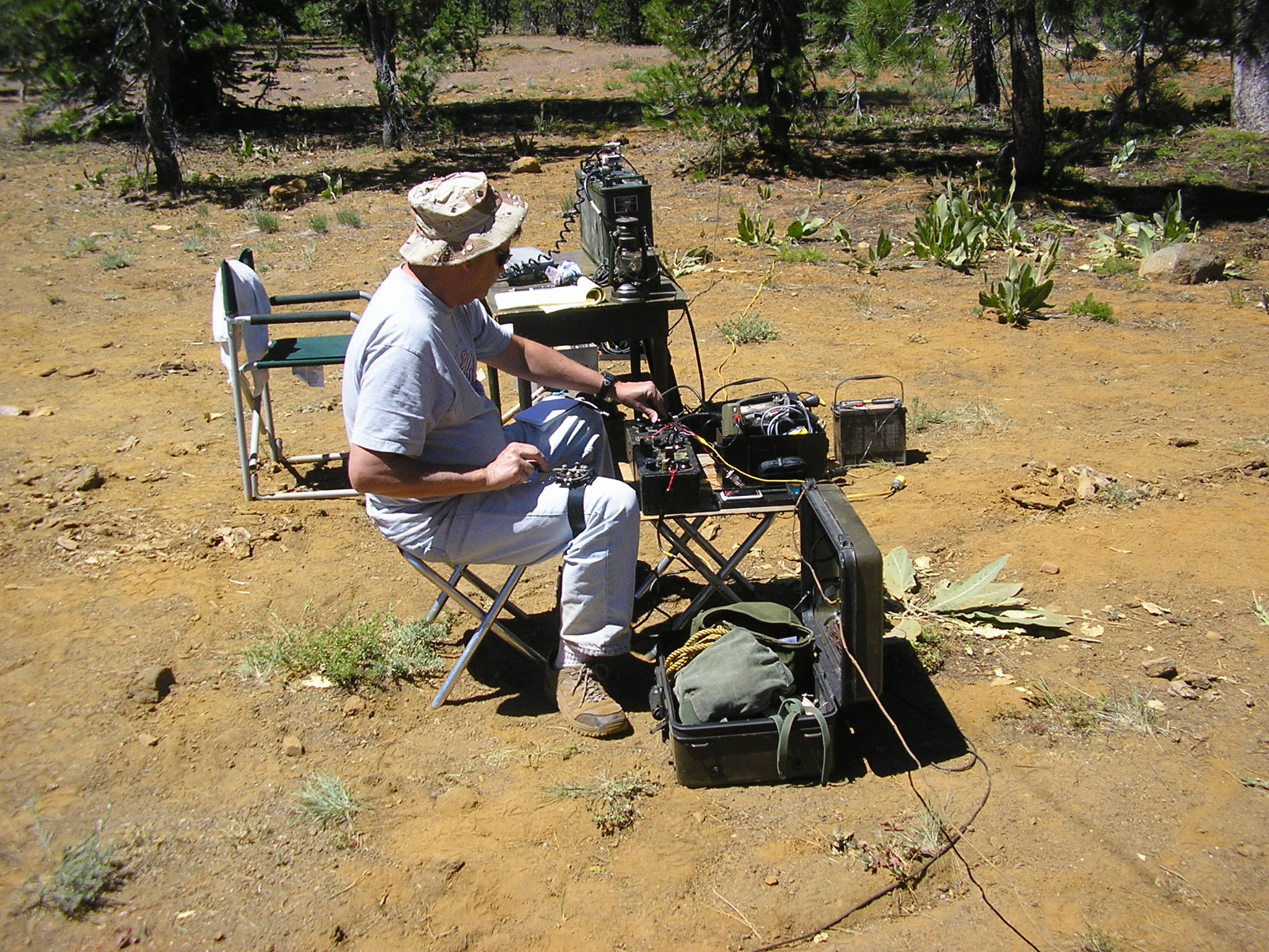
Above: The preliminary GRC-109 / PRC-47 setup. Initial radio checks; everything is working. All that iron in the volcanic soil probably helped with grounding.
Antenna-wise we were also using an interesting antenna in addition to the low dipoles. My buddy brought along a wire antenna captured from the Viet Cong by the U.S. Marines in Vietnam, circa 1968. This war souvenir was set up to be an inverted “L” with about 10 meters of vertical feedline and 33 meters horizontal. Below is the insulator at the junction:

This antenna was made with rubber coated stranded wire and the insulation was mostly falling off during the intervening years. The insulator was broken, as was the end insulator. The “apex” insulator splice seen here was secured with seizing wire made from enamel coated magnet wire. The radio end was a simple open spade lug. We rigged it as an inverted L as it was most likely intended. It worked well with the GRC-109 on 40 meters but our 15 foot high dipole on 60 meters with the PRC-47 worked a little better over the NVIS paths we were working.
This antenna was captured from a Viet Cong or North Vietnamese Army unit working in the “Rocket Belt” around Da Nang. He doesn’t know what radio it may have been connected to at the time. I think it is probably the issued antenna for the ChiCom Type 102E set. The wire looks identical to the antenna wire shipped with the ChiCom surplus Type 102E sets formerly available from Red Star Radio. After we initially connecting it to the GRC-109 receiver we listened carefully for any faint, chirpy 5 character cipher groups using cut numbers, but alas, they had long ago faded away. Long ago and far away……

Above: The vertical-horizontal junction of the Viet Cong Inverted L antenna. A nylon halyard going off to the right from the broken insulator.
For more information about the field antennas used with the GRC-109, take a look here Portable Field Antenna Kit
Epilogue:
The AN/GRC-109 and its father, the RS-1 had an illustrious service life and they have an important place in military communications history. Now they teach us how it was done relatively simply and with reliability in the past, important lessons even today.
In Ham Radio service, the AN/GRC-109 will be operational and operating LOOOONG after those unobtanium dead-column LCD displays and proprietary microscopic microprocessors flame out in all those modern, boring “computers with antenna connectors”.
The AN/GRC-109 is eminently usable in stock configuration, without any “Hammering” modifications by Hams or others. A Radio Operator’s radio.
They will find them very simple to plug together, tune up and make contact. However, today’s “appliance operators” will surely turn up their noses at this set.
One can learn a lot about how the GRC-109 and its relatives performed under combat conditions by taking them to the field and using them today. I’m a believer…….
Di Dah Di Dah Dit

“Yeah – it weighs 10 times more than my plastic KenYaeIc Ricebox and it doesn’t have dual VFO’s, digital readout, variable color dead-columns-of-death LCD display, Digital Signal Processing, roofing filters, a 15 band voice equalizer, 100 watts, RF Preamp, Bandscope, VHF/UHF, microprocessor controls, time-sensitive multiplexed multifunction control buttons, menus, RF processor, direct frequency entry, 500 memories, WiFi, Bluetooth, free software APP’s, or even selectable sidebands or anything. It won’t even enable my computer to automatically Tweet “599” to your computer! It doesn’t even have a USB connector! Whatta piece of junk! ” Exactly.
Your observations, inputs, corrections and comments are most welcomed..
Pay attention in class..The GRC-109 can put out a BIG signal!

————————————————
ADDENDUM
A Modification Mystery: (Chasing Ghosts?) Some “Internet Folklore” has it that the original unlettered, “non-A” T784/GRC-109 transmitter’s did not have the code burst connector/capability. Some or all of them were then somehow subsequently modified to add the code burst connector? “Circular research” posted on the Internet furthers this unfounded assumption.
A modification document sometimes inferred was MWO 11-5820-474-35/1 “Modification of Radio Set AN/GRC-109 to make it Compatible with Coder Burst Transmission Group AN/GRA-71.” This document number and description appears in the Appendix of the GRA-71 manual TM11-5835-224-12 dated May 1964. No mention of it or any related modification appears in the GRC-109 manual through the final Change 6.
It is an odd number sequence since it appears that there never was a “Depot Maintenance” series repair manual that would have been assigned TM11-5820-474-35. The original GRC-109 TM11-5820-474-14 through Change 6 already covered depot level maintenance.
That document number or the occasionally cited “MWO-39” also does not appear in the listing of applicable US Army Index of all Modification Work Orders, DA PAM 310-7 dated May 1967. The US Army does not seem to recognize it beyond that entry in the GRA-71 manual. Neither show up in a search of the CIA’s Freedom of Information Act Electronic Reading Room. Looks like the CIA didn’t own up to it either or at least declassify it.
I have never found an actual Modification Work Order direction or uncovered its date. Did the T784/GRC-109 noted already have the code burst key connector? But then what did this MWO actually accomplish?
Possibly just minor circuit improvements? Apparently MWO-39 installed an RF choke from the CIA transmitters Pi network output to ground (operator HV safety) per spyradios.com. A few T784 examples with low serial numbers have been documented as having 11-5820-474-35/1 stenciled on them. Some RT-3 transmitters have MWO-39 stenciled on the units, so it appears to be “real”. (see Observed Serial Numbers and RT-3 Variants at spyradios.com.)
Some (?) CIA RT-3’s were modified to include the code burst keyer connector to became the CIA’s VERY rare RT/D-3 transmitter. Below is some hardware evidence of that.
Note that the external “KEY” binding post had been removed from this CIA RT-3 transmitter. The hole was enlarged for the 10-pin Winchester M10S connector installation with the original “KEY” label remaining in place. It is very tight behind the panel in this area. Also note the applique over the TYPE RT-3 panel label (which was NOT the T784) now identifies it as the Type RT/D-3 transmitter. Also note the MWO-(39?) paint stamp. The MWO-xx format seems to be CIA versus US Army. See Serial Number 3568 below:
Was this done to enable the CIA with their RS-1/RT-3 to use the CK-8 code burst transmission system they were developing in the late 1950’s? An interim step towards the future GRC-109? Sure looks like it. Below:

The supposedly original unlettered T784 transmitters could not be “modified” by simply “adding” the code burst connector to the front panel. This would also require the relocation of the Receiver antenna post, Ground post and the external Key post that the T784 retained. I’ve never seen a T784 without the burst connector and I’ve looked. Anyone?
The panel layout of the CIA’s RS-1/RT-3 transmitter is different from the GRC-109’s “plain” T784 transmitter. The RT-3:

Versus the T784/GRC-109 below:

Above: Note the location of 3 post connectors plus the 10-pin Burst Keyer connector labeled “KEYER” on this T784/GRC-109. A different layout than the basic RS-1/RT-3 transmitter. The T784/GRC-109’s clearly have different, unique, “not modified” front panels. They were built this way.
(The later T784A/GRC-109 has the same transmitter front panel hole layout, with the addition of the burst keyer connector as the basic design.)
Was the “unlettered” T784 transmitter built as an entirely new transmitter as part of the new GRC-109 from the ground up with the Code Burst connector and its unique front panel layout and labeling? The evidence is very clear.
Tim, really nice article!! 73 de Bart, K6VK ##
Hi Bart – Thanks! We had fun on this camp trip and the field radio(s) make it all that much better. We also had the RS-6 set along but just stuck to the GRC-109 this time.
73, Tim
Thanks for this good description of the GRC-109. I also use a dipole for rx and a wire for rx.
I purchased my units from fair radio about 15 years ago. I was in a unique position to test many of the receivers, transmitters and power supplies and then chose the best. At the time fair had large piles of these units in their warehouse. Few of the units were operationsl up to specs. The vast majority didnt work at all. These radios are old and they should be inspected and be brought up to optimal operation conditions before use. Its unlikely a radio such as the
grc-109 could sit around for 40 or so years and then be fully opeational. This radio is a marvel of design and structure. Its a relatively simple design so repairs are not difficult.
I find that this radio is sooooo much fun to use. Currently I use it on 40 meters CW.
Hi Richard – Thanks for the note. Would have been cool to see a whole pile of these radios back at Fair. I wonder where/when they got theirs. Were they all surplussed at the same time? I wonder if all/most of them came from the same Command/community.
I’ve “been through” 3 transmitters, 2 receivers, and 4 power supplies, all from Fair, late 1980’s. Except for the RT-3 which was basically NIB, and one cranky vibrator they all worked fine the first time I tried them out despite being banged up externally. Their interiors were all pretty much pristine. The gasketed case seal and dessicant tubes seem to do the job – only one switch needed cleaning and that was the Lo-Z antenna capacitance switch in the “new” RT-3.
Usually old radios need switch and pot cleaning at a minimum since most gear of this vintage attracts oxidation but the environmental protection of the ‘109 is very good.. All the other ones I have seen were well worn, likely heavily used in the service. Since they are easy to fix I doubt many field failures were just shelved awaiting higher level repair support. They went back to work. Yes – they should be inspected first, especially the tapped wire wound resistors in the receiver P/S filament circuit – could be an expensive problem if the tap had loosened up and moved.
Of the ones that didn’t work, do you have a sense of what their problems might have been? Were the majority 109’s or 109A’s??
Thanks for the input!
73, Tim
Tim– Thanks for your informative note- I don’t recall the ratio of 109’s to 109A’s. I didn’t particularly like the look of the 109A’s so I purchased the 109’s. I dont know why many units were not operational. I didn’t open up any of the sets I tested. I puchasce three sets( xmitters, receivers, and power supplies. So I now have spares. One set needs repair, I haven’t yet had it looked over I’m not very skilled at radio repair so I had Rich Mish ( the R390 guy) who lives here in Toledo bring two of the sets back up to prime working condition.
I don’t know where Fair purchased these radios. It would be interesting to contact them and ask. I do have old Fair catalogues so recently I checked how the prices and availability of the seperate units changed over the few years that Fair had these in their catalgue. The receivers were the first to go out of stock and next the transmitters. Towards the end Fair sold the emply metal cases You write that you have “been through” 3 transmitters, 2 receivers, and 4 power supplies. I’m curious why you have “been through” them. What happened to them? I ask because perhaps there is a particular ” issue” with these rigs that I should know about to enhance their operational existance.
You show some good photos in your article. One photo is a complete grc 109 in a suitcase. Do you think that this set up would have been likely used in reality? I have one of my grc-109’s in a large very hefty camera case. It weighs alot. I wonder if the suitcase you picture would be able to survive the weight of the radio? Are the large green cases in your photos part of the 109 radio gear? I wonder where I can get one?
Thanks again for your helpful information——and for promoting the awareness of this fine radio.
73, Richard KF2V
Hi Richard – again, thanks for the interest!
I agree – I like the plain ‘109 better – smaller and lighter plus I don’t plan on burying mine or parachuting with it anytime soon. The 109A’s are pretty big with unnecessary clumsy bulk for my interests. But they sure open up more quickly! I’d like to read the reports that caused the Army to request the beefier 109A “upgrades”. That sort of thing is not usually taken lightly so to speak…
“Going thru” the radios: Just to see what kind of shape their internals are in. Fatal curiosity trait of an Engineer. Original tubes? Corrosion? Cooked parts? Date codes? Repairs? In any event, I also put some silicone grease on the panel gaskets and renew the dessicant. Nothing serious except for the new RT-3 that needed a switch cleaning (alcohol on a business card) and then repairing a P/S vibrator. Receiver alignments have generally been “good enough” as received from Fair – I’m not a fanatic. But who knows how much use/abuse these sets have had or how long they were in “stock” and out of operational service before Fair got them…
Suitcase radio: Just a fun photo in a 1940’s suitcase – perfect fit! Yep – way too heavy for that suitcase – the leather handle would have exploded! But without the power supply and the CN-690 regulator instead – would have been quite viable to carry it. The TX and RX are quite light as you know..On the other hand I am sure that during their day many were transported, probably piecewise in suitcases by people who didn’t want to be noticed. In military field service, probably tied to a pack frame or thrown in rucksacks spread among the Team….
That big green case is not part of the 109. I think it was an accessory case for a Dragon missile system. Flea market for $15, perfect case for the complete 109 but very heavy with all the accessories I keep with it. The big power supply stays home usually – the 6VDC battery feature is not very useful these days.
Did you work at Fair? Nice they let you sort through them and pick your favorites. I gotta get back there someday! Do you have an RS-6 set? Take a look at my ramblings on that set on the website…
73, & thanks for visiting….
Tim
Brings back old memories.
Here’s one of mine…..
http://sjcook.com/army/narratives/langvei.htm
Thanx.
A far cry from playing with these on camping trips…
Thanks for your service Sam !
Hi, Tim! I still need to add some write-up of my GRA-71 experiments to my web page one of these days. Maybe we’ll try them out on the air someday if I can come up with an easier way to decode the bursts?
Hi Mark – That was a neat analysis and demodulation scheme you had demonstrated at MRCG12…If you get it operational, let me know and we can try it on a live circuit. Now I just have to figure out how to get my J-38 to work at 300 WPM! LOL
73, Tim
Tim,
Thank you for the nice write up about the GRC-109 sets and the great photos. I found your web page a while ago and check back once in a while to see what is new. It’s always a pleasure. I wish we had your mountains here in Ohio.
When I was at Fair Radio earlier this year they had a few transmitters and power supplies for the 109 sets and some empty cases left over from parts sets that would be useful for building VFOs or holding accessories. Not like the piles that they once had.
Your comment about buried antennas reminded me about the similar idea of trees as antennas. In case you have not seen it already, there is a curious 1972 report called Performance of Trees as Radio Antennas in Tropical Jungle Forests. The idea was to couple a PRC-74 to a tree by wrapping a primary coil around the trunk and using the tree itself as a single turn low impedance secondary winding. It gets into some discussion of relative impedances of oak and pine trees in New Jersey compared to jungle trees in Panama. It also compares transmit and receive performance of trees, whips, and wire antennas. It is online as a PDF here
http://www.dtic.mil/dtic/tr/fulltext/u2/742230.pdf
Bill
Hi Bill – Thanks for checking in! Glad someone reads this stuff LOL….I figured I’d write it down before i forgot it all – and it gives me a good place to keep my photos…I like reading these kinds of posts by other guys so I figured I should contribute to the “cause”…
Yep – that buried antenna scheme apparently worked – I would try it but it is tough to make hollow “pipes” from bamboo but it might be semi-valid to try to bury some PVC pipe and do it that way…Actually I think the pipe does not add anything – if it works, then a buried (insulated) wire should work too. I’m too lazy to dig big trenches so this one may take some more motivation.
I just received an empty GRC-109 TX case from Fair Radio – I designed a 12 VDC powered transistorized HV power supply for both the transmitter and receiver. It works well, now I just have to finish packaging it. I’ll write it up when it’s done..
OK on the mountains situation in Ohio (I wish we had a Fair Radio in California! ;o) – they are pretty close to home here so I get up there often – still lots of remote areas up there to play in.. It’s just fun to play with this stuff outside – mountains or otherwise….
I had read that article on the Tree antennas. Pretty convincing. Thinking outside the box! Tricky to wind the torroidal primary coil but doesn’t look like rocket science…another thing to try at some point…
73 & Happy New Year!
Tim
N6CC
Does PTF-17 ring a bell?
It sure does! Bill was the principal designer and builder of the CRD-21 Comm Center among other feats!
Hi Bill!
Tim
Remarkable. . .if you ever get to london check out the sets at the Imperial War Museum !
Thanks again for fabulous work. Dennis N1imw
Hi & Thanks! Yep, the Imperial War Museum is on my list. A “must” from everyone I have talked with who has been there…
Tim
Was in a reserve unit of the 20th SF, and we had 109’s and practiced with them all the time. I just read throught your very nice article but I seem to have missed the the little squirt keyer we used when talking to Ft. Bragg. Made by Hamilton Watch with a wind-up key on the side and 3 buttons and a send button. Dot/Space/Dash and Send as I remember. Like a tiny type writer that you loaded your one-time pad message into and then ran the recognition so they could get the tape recorders running. Seems to me it ran about 300 words a minute of the spring inside. I figure it was simuliar to an old wire recorder and the Dot/Space/Dash buttons mechanically moved and electrically pinged the tape or wire for the “character”. Real sexy device, size of a silver dollar. Will read the article again, carefullly and see if I missed a description on it there. Best to you all.
Hi Chuck – Thanks for stopping by. That device sounds like the GRA-71 system with the magnetic tape encoders for 300 WPM burst transmissions. I have never had an opportunity to play with one but I have a photo of one on the web posting – see if that’s what you recall. Fifth photo down from the top of the Post. It’s on my list to capture one at some point. I’d like to evaluate one and see how it works but they go for a lot of money these days for some reason.
What did you think of the GRC-109 radio and burst keyer from an operators perspective? In peacetime Ham usage, and under “ideal conditions” they work well and are effective in my experience – but that’s a whole different thing…
Thanks for visiting my WebSite and thanks for your service!
Tim
Love my 109. Does anyone use an external key? Great article!
Joe N8TI
Hi Joe – Well I find the built-in key works quite well for short contacts. It is well placed, is adjustable and feels “right”. For longer operation periods however I usually use an external J-38 or J-45 Knee Key.
Tim
Loved the article, when I heard the code on page one I had to copy it. Couldn’t help myself
Hi GreenBeanie – Yep, code is like that! LOL
We have a dove living in the area – his name is Romeo. He is constantly coo-ing “Wu Wuuuu Wu” “Wu Wuuuu Wu”
And thank you for your service….!
Tim
Didahdidahdit
Hola me llamo Rafael y soy aficionado a las radios antiguas y tengo una radio AN/GRC-9 y tambien e hecho mis comunicados con la radio en AM tengo radios receptores marca Hallicrafters colins y otras mas. E visto vuestro reportage y me a gustado mucho en hora buena por esos equipos y salidas al campo nada mas, saludos de rafael.
Hola Rafael – Gracias por visitar mi página web. El GRC-9 es muy divertido de manejar y es muy fácil para ponerse en marcha. Yo uso la mía mucho cuando voy de campamento y mis compañeros de campamento Creo que es increíble, sobre todo mientras opera CW. La radioafición y camping hace una gran combinación hobby y también proporciona una aplicación muy práctica también. Diviértete con los tuyos! 73, Tim
Hi . I would like to ask if anybody had try to connect on the GRA-71 Keyer Socket any type of interphase to PC …for code and decode CD and RTTY???
Thank you in advance.
Hi Stelios – I don’t know if anyone has tried this. Since that connector is for the GRA-71 CW keyer input, a simple transistor switch-to-ground should key the transmitter. Driven by a computer outputting CW (at 300 WPM) should be doable. The morse training programs on the Web should be able to do that; a computer running fldigi set for CW should be easily adaptable to that task. Decoding it is another problem however! HaHa
RTTY would not work since that requires FSK shifting of the oscillator stage, not simple CW on-off keying. Then it would get very complicated!
Good idea! Anyone?? Anyone got a GSH-11 receiver/decoder laying around for 300 WPM CW?
thanks,Tim
I have had the most of the gear and I use it on 40M, I am using a Kenwood external VFO with my unit and it works very well. I do plan on using thru out the year on the special event stations with the Code Talkers not just the Navajo code talkers but the 33 other tribes that were recognized plus the number of others still pending. The Navajo Code Talkers Special Event stations are usually the weekend of August 14th. The code talkers didn’t use the GRC-109 they used the TBY type radios but all of these are tuff to come by especially when I have to make them operational. I really enjoy this unit, and as I use this on other events I will add an update.
VERY NICE SITE AND EXCELENT PRESENTATION AND FOTOS .I TRY TO USE THE GRC-109 TRANSMITER AS A DSB TRANSMITTER AND THE RESULTS ARE GOOD. I USE A MICROFON PREAMLIFIER AND A XTAL OSCILATOR [EXTERNAL ] AND A NE 602 IC AS BALANCE MODULATOR .PLS SEND ME A MAIL TO SEND BACK DETAILS. MANY 73 TOALL SV8FCF LAMPROS
Hi Lampros & thanks, glad you stopped by. Sure – send us the details on your NE602 modulator! Sounds interesting….
73, Tim
Boy sure brings back memories. When I was in the 7th it was our primary radio set. I used the set in Vietnam (5 th) from A sites to our B team. It was always reliable but did NOT carry it in the field. It was too heavy and bulky as we traveled light and fast. For that we carried the PRC-25, PRC-77 and later the PRC-70. The 70 was a good radio. We did have several PRC-64 and I used several times on CW only. Voice was useless. The PRC-74 was issued to us but it was NOT good in the field, it could not handle the humidity and temperatures. Used it as a backup to the FRC-93 (KWM-2A). When assigned to the 10 th in Germany we used the 109 with the GRA-71 all the time. It was our primary communication. When we were in Ethiopia , I used to send traffic to Germany without any problems. The only place where I did have problem was when we trained in Alaska. Propagation was not always favorable. In all it was a great radio and used it when I was discharged in late 69.
Hi Jean – Nothing like Ground Truth from someone who was there. Thanks very much for your insights on these sets and thank you for checking in.
Thanks for your service!
Tim
The GRC-109 and GRC-109A were in inventories far later that that. The GRC-109 was formerly replaced by the AN/PRC-70/OA-8990 sets in 1982. Some Reserve/ARNG units had the as late as 1985. I served in an ASA Unit in 1988 and we still had GRC-26 Radios in the upstairs of our WW2 barracks at Fort Devens when I left to join CID. PRC-70 Manpacks were turned in to post DRMO in the mid 90’s. the last items were removed from service about 1995 or so.
Hi jj – Very interesting info! Many thanks. PM sent.
Thanks for the trip down memory lane.
Wonderful article and some really fantastic photo’s
Many thanks for the insights into the 109…
Do you know where I can find schematics of the PSU and Receiver?
Many thanks
Ian G3ROO, GB2SPY
Hi Ian – Thanks for visiting the website. It’s been a fun project.
I will send you a link for the manual which includes the schematics.
(I love your Call sign! GB2SPY)
73,,Tim
Back in the early to late 1960’s serving with an Army Intelligence Bn. and with 1st SF I was “introduced” to a disposable radio…Two pieces with one piece being the key device (for Morse) and the other being a burst transmitter. The notion was – key in a message and load it on the transmitter. Send the transmitter aloft on a weather balloon —-at a preset altitude the transmitter would go off. The balloon would continue ’til it burst and the transmitter would, hopefully, be lost forever. I cannot remember the name/designation of the package. Vaguely – each of the two parts were roughly the size of a king sized package of cigarettes. Any idea of the name of these things ?
GRC-109, PRC-47, PRC-25 etc. are all nomenclatures I remember. I was first licensed using a BC-610 in mid-1950’s at the MARS station (University of Hawaii.). Left all that stuff behind when I stopped wearing any colored with green or khaki. Thanks
Hi Eric – Well that’s a new one on me. I know the Army was experimenting in the 1960’s with balloon-raised antennas to overcome jungle attenuation but I didn’t know of any that were actually fielded. Actually, transmission line losses/weight would probably make it impractical. However, “never say never”.
But hoisting up a lightweight transmitter with a pre-loaded message might be workable as you noted. If it was burst CW, maybe a GRA-71 system was used to key one, but I can’t guess as to a disposable transmitter. HF? VHF? UHF? I don’t know. Any visitors have any info on this?
Thanks for visiting my site,,Tim
Very nice website. Just obtained GRC-109 RX and TX. Hope to put them on the air
this coming summer.
Larry, W9QR
Hi Larry – Thanks..A very interesting set as you can tell by my enthusiasm haha. Have fun with it.
73, Tim
Tim
Just read the first part of your “book” I really enjoyed the history and pictures. I am an old SF 05B2SP from the early 70’s. I humped that amazingly reliable heavy SOB, endured hundreds of RF burns and successfully made como for my teams. Thanks for the trip down memory lane.
Great photos and memories. I was a Special Forces Communicator for many years and used the 109 . I was trying to tune mine up but noticed the Power amp light assembly is broken. The one you use to tune with . Any ideas on where to obtain one? Thanks again.
Hi Steve – You might give Fair Radio a call – http://fairradio.com/contact-us/
They sold the radios long ago but I have obtained some replacement parts from them since. Not in their catalog….
Is it the PA tuning (neon lamp) or the antenna tune (incandescent lamp)? Either way, give Fair a call.
Thanks for visiting! Tim
Wow, what an interesting page! Let me tell you how I found it. A couple of weeks ago I was traveling through Lexington KY and stopped into a surplus store. I asked the guy if he had any Vietnam-era web gear. He did not, but he did have some NOS generator carrying cases for dirt cheap. These were still in the box from 1967! In looking up the case I found the generator it was supposed to carry (G-43) and the radio it was supposed to power (GRC-109). And the radio took me to you. As a ham first licensed in the mid-70s, I have dabbled in all sorts of things and have been active then inactive then active, etc. I am just not that interested in the new “high tech” ham radio world and find classic, “in the weeds” stuff like this fascinating. Now I’m interested in obtaining one of these workhorses and seeing what they’re all about. Thanks so much for sharing all of this information.
73 – Mitch, N8XS
Hi Mitch – Glad you found this info to fill out the story on the Generator bag. Many Rabbit Holes to visit when investigating military stuff!
As you can tell, the GRC-109 is one of my favorites, pretty much a “daily driver” for me. Solid engineering, reliable performance, steeped in history..
Good luck on your search, they are around if you dig a bit….Cheers! Tim
I used one when I first got my Ham license down in Panama in the 8th SF Group. I was able to work over 100 countries. Very nice to see the work that has been done with it.
Hi Jay – Thanks for visiting…That’s quite an accomplishment, probably with simple antennas as well? I wonder if you used the 109 operationally with the 8th Group..It’s a very capable rugged radio set, I really enjoy working CW with it, especially while camping…
Thank you for your service! Tim
Tim, wonderful write up! Just a bit of info on the folder marked Gabriel in the picture at the top of the page. That likely refers to the Gabriel Training Area on Fort Bragg, which was located in the old SF area on Smokebomb Hill. We used to run PT through there all the time back in the 80s. My guess is the folder was for commo traffic going to or from units using the training area.
Hi Brian – Ah Ha! Thanks for the visit and input. There’s nothing like Ground Truth from someone who was there…. Tim
Received a T784 (ser#583), R1004A (ser#558A), and PP-2684A (ser# ??) from my father , a long time Ham and former Navy sub radio operator. So many questions, but first is finding a good place for Crystals for the transmitter? Recommendations for an antenna, save the 100′ of 18g wire?
In NW Ohio area if there are other AN/GRC-109 enthusiasts running about.
Hi Chris – Good to hear that your fathers GRC-109 will continue operating. As you can tell, I am a fan of these. As to crystals try steve, AF4K. He has a good selection and is reasonable as these are no longer being made as “originals”…https://www.af4k-crystals.com/
My webpost and related posts discuss many possible antenna types for the 109 or any other radio…Even a simple wire. Have fun with it..Tim
The photograph marked “Gabriel” does not match anything from the Special Forces Training Center that I remember. It is unlikely to be a training-group picture. We did not practice C-Team communications. The picture is far more likely to be what it says it is, a fake operation set up at Gabriel to impress visiting Congress members. I was an 05B4S at Fort Bragg from early 1968 (training group) to mid-1970 (ETS). Thank you for sharing this long history.
Hi David – Thanks for the info, “ground truth” is always appreciated. The guy who sent me the photo and accompanying info wished to remain anonymous but he was not the SGT in the photo. I can’t comment on the location but it does look to me to be a functioning comm setup – all the necessary equipment is there. (I have many hours on both the GRC-109’s and the R-390.) Someone did a nice job with it all.
However I am pretty sure it is a “staged” photo op: The SGT has his left hand on the CW key and a pencil/writing with his right hand, something I think no one would ever actually do simultaneously. “I wasn’t there…” haha
Thanks for visiting and thank you for your service Soldier.. Tim
Oh, my! Thanks for bringing back lots of memories. I used this equipment while in Special Forces Vietnam 1966/1967. I even liberated a set as it somehow found its way into my ‘hold baggage’ on return to Land of All Night Generator. Wish I still had it but I ‘lost’ it during hard times after ETS.
Thanks again and 73
K3GB
A-103/A-109
Hi Gary – Thanks for visiting and thank you for your service.
“Land of All Night Generator” haha indeed….Love it!!
looking for a complete GRC-109 as issued.
I have several unique radios that I will trade.
The radios will make the person that gets them very happy.
Military radios are date back as for as 1917, and go as far as 80’s.
I was a member of MACVSOG CCN from April 1969 to October 1970. Initially I ran the Commo Shack in the TOC. We did not use the ANGRC-109 and I never saw one in the Commo Shack. Later I was on RT Diamondback and later RT Louisiana. We carried PRC-25s initially and then with the “scrambler”. Never 109s.
In 1967 at my Special Forces A-team, A-322 at Prek Klok and Katum, we were supposed to use the ANGRC 109 to communicate with Nha Trang, to ensure we were keeping up with our commo skills and sending code. I used a Collins KWM2-A. Nha Trang always said I was 5 X 5. 100watts versus 15 at best.
Hi Laurie – many thanks for the “ground truth” note. Looks like the 109’s had been replaced as primary sets by the KWM-2A’s at your locations and by those later dates. That certainly makes sense at TOC’s at the time.
Thank you for your service! Tim
Howdy Tim, thanks for doing a deep-dive on the 109 and sharing the notes from your many years of research and experience with it. You’re a very good writer too; I like your style! I’ve learned a lot and improved my own 109 setup based on your lessons learned.
I made a 12V to 6V converter to battery-power my setup in the field and I didn’t get so much vibrator hash from my ‘GRC-109A’ version of the big power supply as to make the system unusable.
My vibrator didn’t work as received, so I first had to cut it open to clean and bend the contacts to tune it up so it would work. There were signs of heat and burned contacts from a previous user, so I believe it’s a design that can be made to work and was used, at least until the vibrator gives out.
I now use a much lighter weight and more efficient power supply. I had a partly cannibalized small power supply. I cleaned it out the rest of the way and put in four 12V DC-DC converter modules to supply the needed 1.35, 6.3, 100, and 450V, all nicely regulated. I added banks of LC filters on the inputs and outputs, and there is no detectable power supply noise in the receiver.
I replaced the meter with a DC one, and wired the rotary switch so the meter can read the input and all the output voltages. I replaced the AC cord with wires and battery clips.
It works great and almost looks like it was one of the original power supply options. Improvise, adapt, overcome.
As you said above, when transmitting, the receiver overloads and the oscillator pulls, making it hard to accurately spot your TX frequency with the receiver. I made a little accessory board with a SPDT toggle switch that disconnects the antenna and shorts the RX antenna input to ground. The board has a couple stiff wires spaced for the ANT and GND terminals, and a jack for the antenna wire coming in. To spot, I just flip the switch, transmit, tune the receiver to my desired beat note, and flip back to receive. I’ve had good luck with it, and it beats physically disconnecting the antenna wire every time I wanted to spot my TX QRG like I was doing before.
The 109 is my favorite radio for field commo exercises and it always makes my (or both of our) day(s) when the guy I catch with my CQ perks up, says he’s proud to be on the other end of a 109 QSO, and tells me about his service in Vietnam.
73, Hank – WV7U
Hi Hank – Thanks for checking in and including your details. A nice “mod” to utilize an old AC power supply carcass..Well done.
Regarding RX freq pulling during transmit I have found that just reducing the RX gain control all the way down allows adequate spotting. An annoyance but workable. K4CHE (see his website) installed a T/R antenna relay inside the transmitter to further isolate the receiver when transmitting. The key then drives the relay which switches a common antenna between the TX and RX, seems like a good mod. Shorting the RX antenna via the key while transmitting was the original design but there is still too much coupling involved.
Thanks for visiting and glad you found some of my stuff useful. Tim